

Motor Vehicle Tire Safety Regulations, 1995
SOR/95-148
Registration 1995-03-21
Regulations Respecting Safety for Motor Vehicle Tires
P.C. 1995-461 1995-03-21
Whereas, pursuant to subsection 11(3) of the Motor Vehicle Safety ActFootnote *, a copy of proposed Regulations respecting safety for motor vehicle tires, substantially in the form annexed hereto, was published in the Canada Gazette Part I on December 10, 1994, and a reasonable opportunity was thereby afforded to interested persons to make representations to the Minister of Transport with respect thereto;
Return to footnote *S.C. 1993, c. 16
Therefore, His Excellency the Governor General in Council, on the recommendation of the Minister of Transport, pursuant to subsection 3(2) and sections 5, 7, 10 and 11 of the Motor Vehicle Safety ActFootnote *, is pleased hereby to revoke the Motor Vehicle Tire Safety Regulations, C.R.C., c. 1039, and to make the annexed Regulations respecting safety for motor vehicle tires, in substitution therefor, effective April 12, 1995.
Short Title
1 These Regulations may be cited as the Motor Vehicle Tire Safety Regulations, 1995.
Interpretation
2 In these Regulations,
- Act
Act means the Motor Vehicle Safety Act; (Loi)
- bead
bead means that part of a tire, made of steel wires wrapped or reinforced by plies, that is shaped to fit the rim; (talon)
- bead separation
bead separation means a breakdown of bond between components in the bead; (séparation du talon)
- bias ply tire
bias ply tire means a tire in which the plies that extend to the beads are laid at alternate angles substantially less than 90 degrees to the centreline of the tread; (pneu à carcasse diagonale)
- bus
bus has the same meaning as in subsection 2(1) of the Motor Vehicle Safety Regulations; (autobus)
- carcass
carcass means the structure of a tire without the tread and sidewall rubber; (carcasse)
- chassis-cab
chassis-cab has the same meaning as in subsection 2(1) of the Motor Vehicle Safety Regulations; (châssis-cabine)
- chunking
chunking means the breaking away of pieces of the tread or sidewall of a tire; (arrachement)
- cord
cord means the strands forming the plies of a tire; (câblé)
- cord separation
cord separation means the parting of cords from adjacent rubber compounds; (séparation de câblés)
- cracking
cracking means any parting within the tread, sidewall or innerliner of a tire extending to the cord; (fissuration)
- CT tire
CT tire means a tire that is designed to be mounted on a rim in such a manner that the flanges of the rim extend radially inward so as to be enclosed inside the air cavity of the tire; (pneu anti-affaissement)
- innerliner
innerliner means the layers that contain the inflating medium within a tire and form the inside surface of a tubeless tire; (calandrage intérieur)
- innerliner separation
innerliner separation means the parting of the innerliner from the cord; (séparation du calandrage intérieur)
- light truck tire
light truck tire [Repealed, SOR/2008-258, s. 11]
- light-truck tire
light-truck tire or LT tire has the same meaning as in subsection 2(1) of the Motor Vehicle Safety Regulations; (pneu pour camion léger)
- load range
load range means a letter designation that indicates the maximum load rating of a tire; (limite de charge)
- load rating
load rating means the maximum load a tire is rated to carry at a given inflation pressure; (charge nominale)
- maximum load rating
maximum load rating means the load rating at the maximum permissible inflation pressure for a tire; (limite de charge nominale)
- maximum permissible inflation pressure
maximum permissible inflation pressure means the maximum cold inflation pressure to which a tire may be inflated for normal highway use; (pression maximale permise de gonflage)
- motorcycle
motorcycle has the same meaning as in subsection 2(1) of the Motor Vehicle Safety Regulations; (motocyclette)
- multipurpose passenger vehicle
multipurpose passenger vehicle has the same meaning as in subsection 2(1) of the Motor Vehicle Safety Regulations; (véhicule de tourisme à usages multiples)
- open splice
open splice means any parting at any junction of tread, sidewall or innerliner that extends to the cord; (séparation de soudure)
- overall width
overall width means the linear distance between the exteriors of the sidewalls of an inflated tire, including elevations due to labelling, decorations or protective bands; (largeur hors tout)
- passenger car
passenger car has the same meaning as in subsection 2(1) of the Motor Vehicle Safety Regulations; (voiture de tourisme)
- ply
ply means a layer of rubber-coated parallel cords; (pli)
- ply separation
ply separation means the parting of the rubber compound between adjacent plies of a tire; (décollement entre nappes)
- radial ply tire
radial ply tire means a tire in which the plies that extend to the beads are laid at substantially 90 degrees to the centreline of the tread; (pneu à carcasse radiale)
- rim
rim means a support for a tire or a tire and tube assembly on which the beads are seated; (jante)
- rim diameter
rim diameter has the same meaning as in subsection 2(1) of the Motor Vehicle Safety Regulations; (diamètre de jante)
- section width
section width means the linear distance between the exteriors of the sidewalls of an inflated tire, excluding elevations due to labelling, decorations or protective bands; (grosseur du boudin)
- sidewall
sidewall means that portion of a tire between the tread and the bead; (flanc)
- sidewall separation
sidewall separation means the parting of the rubber compound from the cord in the sidewall; (séparation des flancs)
- size factor
size factor means the aggregate of the section width and the outer diameter of a tire determined on the test rim; (coefficient de dimension)
- test rim
test rim, with reference to a tire to be tested, means any rim that is listed as appropriate for use with that tire in accordance with a tire and rim document where the document includes the dimensional specifications of the rim and a diagram of the rim; (jante d’essai)
- tire and rim document
tire and rim document means a document or publication referred to in section 7; (document relatif aux pneus et aux jantes)
- trailer
trailer has the same meaning as in subsection 2(1) of the Motor Vehicle Safety Regulations; (remorque)
- trailer converter dolly
trailer converter dolly has the same meaning as in subsection 2(1) of the Motor Vehicle Safety Regulations; (chariot de conversion)
- tread
tread means that portion of a tire that comes into contact with the road; (bande de roulement)
- tread rib
tread rib means a tread section running circumferentially around a tire; (nervure de la bande de roulement)
- tread separation
tread separation means the parting of the tread from the carcass; (séparation de la bande de roulement)
- truck
truck has the same meaning as in subsection 2(1) of the Motor Vehicle Safety Regulations; (camion)
- SOR/2008-258, s. 11
3 For the purposes of Schedules IV and V, where a company uses one of the systems of measurement set out in these Regulations to determine whether a tire meets the requirements of any section of those Schedules, that company shall continue to use that same system of measurement to determine the conformity of that tire to any other section of those Schedules.
National Safety Mark
4 Where a company authorized by the Minister in the form set out in Schedule I applies the national safety mark to a tire, that mark shall
(a) be the symbol set out in Schedule II of the Act;
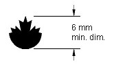
(b) have the minimal dimension indicated in Schedule II; and
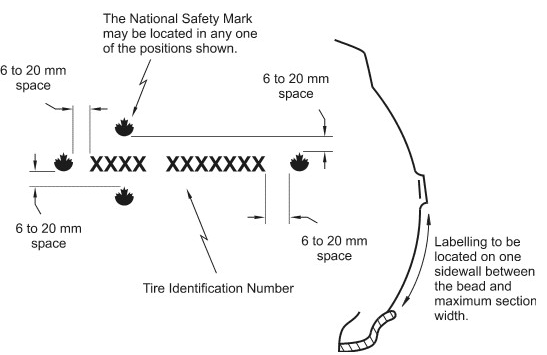
(c) be permanently moulded into or onto one sidewall of the tire in the manner and location specified in Part II of Schedule III.
Prescribed Tires and Safety Standards
5 (1) Tires for passenger cars are prescribed as a class of equipment for the purposes of section 5 of the Act.
(2) Every tire for passenger cars shall conform to the applicable standards set out in Schedule IV (Safety Standard 109).
6 (1) Tires for buses, chassis-cabs, motorcycles, multipurpose passenger vehicles, trailers, trailer converter dollies or trucks are prescribed as classes of equipment for the purposes of section 5 of the Act.
(2) Every tire for a bus, chassis-cab, motorcycle, multipurpose passenger vehicle, trailer, trailer converter dolly or truck shall conform to the applicable standards set out in Schedule V (Safety Standard 119).
Tire Information
7 (1) Subject to subsection (2), every company shall provide to its dealers, to the Minister at the address indicated in Schedule VI, and to any person who requests it, the following information in respect of each tire of a specific size designation and type that it manufactures:
(a) a list of the rims designed for use with that tire, and a diagram and the dimensions of each of those rims;
(b) a table showing, for a tire of a specific size designation, the type of construction and the intended use of that tire together with the various load ratings; and
(c) a table and diagram showing the dimensions of that tire.
(2) A company is not required to comply with subsection (1) where
(a) the information specified in subsection (1) appears in a publication issued by any of the following:
(i) the Tire and Rim Association,
(ii) the European Tyre and Rim Technical Organisation,
(iii) the Japan Automobile Tire Manufacturers’ Association, Inc.,
(iv) the Deutsche Industrie Norm,
(v) the British Standards Institution,
(vi) the Scandinavian Tire and Rim Organization (STRO),
(vii) the Tyre and Rim Association of Australia,
(viii) the Associação Latino Americana de Pneus e Aros (ALAPA),
(ix) the Tire and Rim Engineering Data Committee of South Africa (Tredco),
(x) the South African Bureau of Standards,
(xi) the Indian Tyre Technical Advisory Committee (ITTAC), or
(xii) the Instituto Argentino de Normalización y Certificación (IRAM); and
(b) each tire that it manufactures corresponds to a tire of a specific size designation and type described in a publication referred to in paragraph (a).
- SOR/2003-272, s. 35
- SOR/2008-258, s. 12
Tire Identification
General
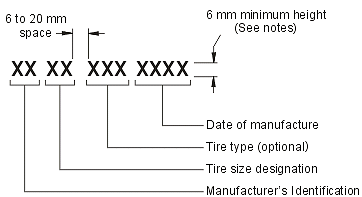
8 (1) Every tire shall have permanently moulded into or onto one of its sidewalls, in the manner and location specified in Schedule III, a tire identification number consisting of the following groups of symbols:
(a) two symbols approved by the Minister or by the United States National Highway Traffic Safety Administration that identify the manufacturer of the tire;
(b) two symbols that identify the tire size;
(c) not more than four symbols that
(i) identify the owner of the brand name, if applicable, and
(ii) at the manufacturer’s option, form a code for the purpose of identifying the significant characteristics of the tire; and
(d) two symbols that identify the week of manufacture of the tire and two symbols that identify the year of manufacture of the tire, as follows:
(i) the first two symbols shall identify the week of manufacture of the tire using “01” for the first week of the year, “02” for the second week, and so on,
(ii) for the purposes of subparagraph (i), a week begins on Sunday and ends on Saturday, and the final week of the year may include not more than six days of the following year,
(iii) the last two symbols shall identify the year of manufacture of the tire and shall consist of the last two digits of the year, and
(iv) at the manufacturer’s option, the symbols may, not later than 24 hours after the tire is removed from the mould, be laser-etched into the sidewall rather than permanently moulded into or onto the sidewall.
(2) No person shall alter, deface or remove a tire identification number.
- SOR/2000-114, s. 1
- SOR/2008-258, s. 13
Tires for Passenger Cars
9 (1) Every tire referred to in section 5 shall have permanently and legibly moulded into or onto
(a) both sidewalls of the tire, in letters and numerals not less than 2.0 mm (0.078 in.) in height,
(i) the tire size designation, expressed in metric units or Imperial units or both,
(ii) the maximum permissible inflation pressure, expressed in kilopascals or pounds per square inch or both,
(iii) the maximum load rating, expressed in kilograms or pounds or both,
(iv) the generic name of the material used in the cord of the sidewall and tread,
(v) the actual number of plies in the sidewall and, if different, the actual number of plies in the tread,
(vi) a word or expression indicating that the tire contains a tube or does not contain a tube, as the case may be, and
(vii) the word “radial” if the tire is a radial ply tire; and
(b) at least one sidewall of the tire,
(i) the name of the tire manufacturer, or
(ii) the brand name of the tire and the symbols that identify the tire manufacturer.
(2) In addition to the information set out in subsection (1), every tire that has a maximum permissible inflation pressure of 415 kPa (60 p.s.i.) shall have permanently and legibly moulded into or onto both sidewalls of the tire, in letters and numerals not less than 12 mm (0.5 in.) in height, words expressing a maximum permissible inflation pressure in kilopascals or in pounds per square inch, or both, between shoulder and bead of the tire in such a manner that the words are not obstructed by the rim flange.
Tires for Vehicles Other Than Passenger Cars
10 (1) Every tire referred to in section 6 shall have permanently and legibly moulded into or onto
(a) both sidewalls of the tire, in letters and numerals not less than 2 mm (0.078 in.) in height and raised above or sunk below the tire surface not less than 0.38 mm (0.015 in.), unless the tire is a tire referred to in paragraph (b) or (c),
(i) the tire size designation as listed in a tire and rim document,
(ii) the following words and numerals to indicate the maximum load rating and corresponding tire inflation pressure, namely,
(A) if the tire is rated for both single and dual load, “Max. load single
 kg at kPa cold, Max. load dual kg at kPa cold”, or
(B) if the tire is rated for single load only, “Max. load
kg at kPa cold”,
(iii) if the tire is restricted to a speed of 88.5 km/h (55 m.p.h.) or less, the words and numerals “Max. speed
km/h”,(iv) the actual number of plies and the composition of the cord material in the sidewalls and the actual number of plies and the composition of the cord material in the tread area, if different,
(v) the word “tubeless” or the expression “tube type”, whichever is applicable to the tire type,
(vi) the word “regroovable” if the tire is designed for regrooving,
(vii) the word “radial” if it is a radial ply tire, and
(viii) the letter that designates the tire load range;
(b) at least one sidewall of a motorcycle tire, in letters and numerals not less than 2 mm (0.078 in.) in height and raised above or sunk below the tire surface not less than 0.25 mm (0.01 in.), the information specified in paragraph (a); and
(c) at least one sidewall of a recreational trailer tire, boat trailer tire, baggage trailer tire and special trailer tire, in letters and numerals not less than 2 mm (0.078 in.) in height and raised above or sunk below the tire surface not less than 0.38 mm (0.015 in.), the information specified in paragraph (a).
(2) The information required by subsection (1) shall
(a) where required to be moulded onto or into both sidewalls of the tire, be moulded onto or into at least one sidewall between the maximum section width and the bead of that sidewall;
(b) where the maximum section width of the sidewalls of the tire is located within the lower quarter of the sidewalls, be moulded onto or into the lower half of a sidewall; and
(c) where paragraph (1)(b) or (c) applies to the tire, be moulded anywhere onto or into a sidewall.
(3) The information required by subparagraphs (1)(a)(i) to (iii) may be specified in Imperial units or Imperial and metric units.
Records
11 (1) Subject to subsection (3), for each tire to which the national safety mark is applied, a company shall maintain in writing or in readily readable electronic or optical form the records referred to in paragraph 5(1)(g) of the Act that show that the tire conforms to all prescribed standards applicable to it and retain those records for at least three years after the date of manufacture or importation.
(2) Where the records referred to in subsection (1) are maintained on behalf of a company, the company shall keep the name and address of the person who maintains those records.
(3) Where a tire is imported from the United States in accordance with subsection 13(2), the record maintained by a manufacturer for that tire, and available to the Administrator of the United States National Highway Traffic Safety Administration in accordance with section 30166 of Title 49 United States Code, “Transportation”, chapter 301 Motor Vehicle Safety, shall be considered to meet the requirements of paragraph 5(1)(g) of the Act.
- SOR/95-536, s. 8
- SOR/98-524, s. 5
- SOR/2008-104, s. 24
Registration Systems
12 (1) The registration system referred to in paragraph 5(1)(h) of the Act shall contain
(a) the tire identification number of each tire manufactured, imported or sold by the company; and
(b) the name and address of the purchaser of each tire.
(2) The information kept in the registration system maintained by or on behalf of a company shall be retained for at least three years after the date of sale of the tire to which the information relates.
Importation
13 (1) For the purposes of paragraph 5(1)(b) of the Act, a company, other than a company referred to in subsection 14(3), that imports a tire shall maintain records setting out
(a) the name of the manufacturer of the tire;
(b) the name of the company importing the tire;
(c) a statement that on the date of its importation the tire complied with these Regulations;
(d) a statement from the manufacturer of the tire or its duly authorized representative that the tire complied with subsection 5(2) or 6(2) on the date of its completion;
(e) the brand name, type and size designation of the tire and the number of tires of that type and size designation imported at the same time; and
(f) the date of importation of the tire.
(2) Where a tire is imported from the United States, the company importing the tire may replace the statement referred to in paragraph (1)(d) with a statement that the tire was manufactured for sale in the United States and meets all the requirements established under chapter 301 Motor Vehicle Safety of Title 49 United States Code, “Transportation”.
(3) A person or the person’s duly authorized representative that imports a tire pursuant to paragraph 7(1)(a) of the Act shall, prior to importation, file with the Minister the signed declaration referred to in that paragraph that contains the information set out in Schedule VII.
- SOR/95-536, s. 8
Tires Imported from a Country other than the United States for Retreading
14 (1) A tire may be imported from a country other than the United States for the purpose of retreading if
(a) it can be shown by a national safety mark, a DOT symbol as used by the United States Department of Transportation or a JIS symbol as used by the Japanese Standards Association on the tire that, at the time of manufacture, the tire conformed to the applicable standards set out in Schedule V (Safety Standard 119), the United States Federal Motor Vehicle Safety Standard No. 119 or the Japanese Industrial Standard JIS D 4230;
(b) the tire is designed to fit on a rim having a nominal diameter of greater than 406.4 mm (16 in.);
(c) the tire is listed in a publication referred to in subsection 7(2);
(d) the tire has, as specified for a tire of that size designation and type in a publication referred to in subsection 7(2),
(i) a load range of not less than D, or
(ii) a ply rating of not less than 8;
(e) the tire has been used;
(f) the tire has never been retreaded;
(g) no notice of defect has been issued in respect of the tire in the country in which it was manufactured;
(h) there is no steel or fabric showing;
(i) the crown and sidewall plies are not visible and are not affected by cuts;
(j) there is no bead damage that could allow air leakage, cause abrasion damage to the bead components, or affect the proper bead seating to the rim; and
(k) the repairs to the crown area required to prepare the tire for retreading are limited to surface skiving, cleaning out of dirt and debris and smoothing out.
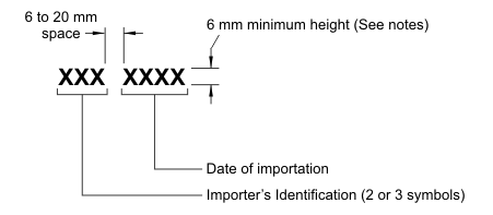
(2) A company that imports a tire referred to in subsection (1) shall, before the tire is sold at retail, have an importer identification number permanently moulded into or onto one sidewall of the tire, in the manner set out in Part I of Schedule III and in the same location set out in Part II of that Schedule for the tire identification number, which importer identification number shall consist of the following groups of symbols:
(a) two or three symbols assigned by the Minister that identify the importer; and
(b) two symbols that identify the month of importation of the tire and two symbols that identify the year of importation of the tire.
(3) For the purposes of paragraph 5(1)(b) of the Act, a company that imports a tire referred to in subsection (1) shall maintain records setting out
(a) the name of the company;
(b) the type and size designation of the tire and the number of tires of that type and size designation imported at the same time; and
(c) a signed declaration by the company or the duly authorized representative of that company stating
(i) that the tire complied with the requirements of these Regulations as they read on the date of importation,
(ii) that no notice of defect has been issued in respect of the tire in the country in which it was manufactured, and
(iii) that the tire will not be sold at retail before it is retreaded.
(4) A registration system referred to in paragraph 5(1)(h) of the Act may consist of records maintained by a company that imports a tire referred to in subsection (1) if the records show to whom the tire was sold.
- SOR/2008-258, s. 14
Defect Information
15 (1) A notice of defect referred to in subsections 10(1) or (3) of the Act shall be given in writing and shall indicate
(a) the name of the company giving the notice;
(b) the identifying classification of each tire in respect of which the notice is given, including its brand name, type and size designation, the period during which it was manufactured and the tire identification number;
(c) the estimated percentage of the potentially affected tires that contain the defect;
(d) a description of the defect;
(e) an evaluation of the safety risk arising from the defect;
(f) a statement of the measures to be taken to correct the defect; and
(g) any conditions that influence the rectification of the defect.
(2) A company shall, within 30 days after it has given a notice of defect, submit to the Minister a report referred to in subsection 10(6) of the Act containing, in addition to the information required by subsection (1), the following information:
(a) the total number of tires affected by the notice of defect and the number of such tires in each identifying classification;
(b) a chronology of all principal events that led to the determination of the existence of the defect; and
(c) copies of all notices, bulletins and other circulars issued by the company in respect of the defect, including a detailed description of the nature and physical location of the defect with diagrams and other illustrations as necessary.
(3) For the purposes of subsection 10(6) of the Act, the quarterly reports to be submitted following the report referred to in subsection (2) shall contain the following information:
(a) the number, title or other identification assigned by the company to the notice of defect;
(b) the revised number of tires affected by the notice of defect, if applicable;
(c) the date notices of defect were given to the current owners of the tires;
(d) the number of tires inspected by or at the direction of the company;
(e) the number of inspected tires found to contain the defect; and
(f) a statement outlining the manner in which the company disposed of the defective tires.
- SOR/95-536, s. 8
- SOR/98-524, s. 6
- SOR/2008-104, s. 25
SCHEDULE I(Section 4)
Department of TransportMotor Vehicle Safety Act (subsection 3(2))
Motor Vehicle Tire Safety Regulations, 1995 (section 4)
Ministerial Authorization
Pursuant to the Motor Vehicle Safety Act and the Motor Vehicle Tire Safety Regulations, 1995,
[company name and address]
is authorized to use and apply the national safety mark, and the authorization number , to any motor vehicle tire of a class referred to in sections 5 and 6 of the Motor Vehicle Tire Safety Regulations, 1995, on condition that the tire conforms to all the applicable Canada Motor Vehicle Safety Standards.
The national safety mark and the authorization number are applied at the following premises: [identification of the premises]
This ministerial authorization expires on
Issued in Ottawa on , 20
for the Minister of Transport, Infrastructure and Communities
- SOR/2008-104, s. 26
SCHEDULE II(Section 4)
NATIONAL SAFETY MARK
SCHEDULE III(Paragraph 4(c) and subsections 8(1) and 14(2))
PART I
Tire Identification Number
Importer Identification Number
Notes:
- 1For tires less than 155 mm in cross-section or less than 330 mm in bead diameter, the minimum height of the lettering of the Tire Identification Number may be 4 mm.
- 2The characters of the National Safety Mark and the Tire Identification Number shall be moulded into or onto the tire at a height or depth of not less than 0.5 mm and not more than 1 mm, as measured from the immediate surrounding surface of the tire.
- 3The Identification Number shall be in Futura Bold, Modified, Condensed or Gothic characters or any other font approved by the Minister.
- 4The date of manufacture that is part of the Tire Identification Number shall be permanently moulded or laser etched, at the manufacturer’s option. The date of importation that is part of the Importer Identification Number shall be permanently moulded.
PART II
Location of Tire Identification Number and National Safety Mark
- SOR/2000-114, s. 2
- SOR/2008-258, s. 15
SCHEDULE IV(Section 3 and subsection 5(2))Safety Standard 109 for Passenger Car Tires
General
1 (1) Every tire of a particular size designation and type shall
(a) be designed to fit a rim having a designated diameter of 254, 279, 305, 330, 356, 381, 406, 432, 457 or 483 mm (10, 11, 12, 13, 14, 15, 16, 17, 18 or 19 in.) or 320, 340, 345, 365, 370, 390, 400, 415, 425, 450, 475 or 500 mm;
(b) be designed to fit each rim specified for a tire of that size designation and type in a tire and rim document;
(c) have, in the case of CT tires, a maximum permissible inflation pressure of 290, 330, 350 or 390 kPa (42, 48, 51 or 57 p.s.i.);
(d) have a maximum permissible inflation pressure of 220, 240, 250, 275, 280, 300, 340, 350 or 415 kPa (32, 35, 36, 40, 41, 44, 50, 51 or 60 p.s.i.);
(e) have load ratings and corresponding inflation pressures for a tire of that size designation and type as specified in a tire and rim document;
(f) subject to subsection (2), have a maximum load rating that is not less than the maximum load rating specified for a tire of that size designation and type in a tire and rim document; and
(g) incorporate a treadwear indicator that will provide a visible indication that the tire has worn to a tread depth of 1.6 mm (1/16 in.).
(2) Where a publication referred to in subsection 7(2) of these Regulations sets out more than one maximum load rating for a tire of a particular size designation and type, the required maximum load rating for the purposes of paragraph (1)(f) shall be not less than the lowest of the maximum load ratings set out in the publication.
Rules Respecting Testing
2 For the purpose of conducting tests under subsections 4(2), 5(2), 6(2), 7(2) and 8(2), three similar new tires shall be used as follows:
(a) one tire for the test for physical dimensions, the bead unseating resistance test and the tire strength test, in that sequence;
(b) one tire for the tire endurance test; and
(c) one tire for the high speed performance test.
3 Before being subjected to the tire endurance test set out in subsection 7(2) or the high speed performance test set out in subsection 8(2), a tire of a particular size designation and type shall have no visible evidence of tread separation, sidewall separation, ply separation, cord separation, innerliner separation, bead separation, chunking, broken cords, cracking or open splice.
Physical Dimensions of Tires
4 (1) Where a tire of a particular size designation and type is tested for physical dimensions in accordance with subsection (2), the tire shall have
(a) a tolerance in respect of section width and overall width that
(i) in the case of a tire with a maximum permissible inflation pressure of 220, 250 or 275 kPa (32, 36 or 40 p.s.i.), is not greater than seven per cent in excess of the section width specified in a tire and rim document for a tire of that size designation and type, or
(ii) in the case of a tire with a maximum permissible inflation pressure of 240, 280, 290, 300, 330, 340, 350, 390 or 415 kPa (35, 41, 42, 44, 48, 50, 51, 57 or 60 p.s.i.), is not greater than seven per cent in excess of the section width specified in a tire and rim document for a tire of that size designation and type, or 10 mm (0.4 in.), whichever is greater; and
(b) a size factor that is not less than the minimum size factor specified in a tire and rim document for a tire of that size designation and type.
(2) The test for the physical dimensions of a tire shall be carried out under uniform ambient conditions by
(a) mounting the tire on a test rim and inflating it to the pressure set out in column II of an item of Table II for the maximum permissible inflation pressure set out in column I of that item;
(b) conditioning the tire and rim assembly at ambient temperature for at least 24 hours and then adjusting the inflation pressure of the conditioned tire to the pressure referred to in paragraph (a);
(c) measuring with calipers the section width and overall width of the tire at six points approximately equally spaced around the tire circumference;
(d) recording the average of the measurements of the section width and overall width, respectively; and
(e) determining the tire’s outer diameter by measuring the maximum circumference of the tire and dividing it by pi(3.14).
Bead Unseating Resistance of Tubeless Tires
5 (1) Where a tubeless tire of a particular size designation and type is tested for bead unseating resistance in accordance with subsection (2), the tire shall, using the test rim width specified in a tire and rim document for a tire of that size designation and type,
(a) in the case of a tire with a maximum permissible inflation pressure other than 415 kPa (60 p.s.i.), require an applied force to unseat the tire bead at the point of contact of that force of not less than
(i) 6 670 N (1,500 lb.) for a tire with a designated section width, as marked on the sidewalls, of less than 155 mm (6 in.),
(ii) 8 895 N (2,000 lb.) for a tire with a designated section width, as marked on the sidewalls, of 155 mm (6 in.) or more but less than 205 mm (8 in.), and
(iii) 11 120 N (2,500 lb.) for a tire with a designated section width, as marked on the sidewalls, of 205 mm (8 in.) or more; and
(b) in the case of a tire with a maximum permissible inflation pressure of 415 kPa (60 p.s.i.), require an applied force to unseat the tire bead at the point of contact of that force of not less than
(i) 6 670 N (1,500 lb.) for a tire with a maximum load rating of less than 400 kg (880 lb.),
(ii) 8 895 N (2,000 lb.) for a tire with a maximum load rating of 400 kg (880 lb.) or more but less than 635 kg (1,400 lb.), and
(iii) 11 120 N (2,500 lb.) for a tire with a maximum load rating of 635 kg (1,400 lb.) or more.
(2) The tubeless tire bead unseating resistance test shall be performed by
(a) washing the tire, drying it at the beads and mounting it without lubrication or adhesive onto a clean, painted test rim;
(b) inflating the tire to the applicable inflation pressure set out in column II of an item of Table II for the maximum permissible inflation pressure set out in column I of that item;
(c) mounting the tire and rim assembly onto the bead unseating fixture shown in Figure 1 and
(i) for a tire that has a maximum permissible inflation pressure of other than 415 kPa (60 p.s.i.), forcing the bead unseating block, as shown in Figure 2, against the tire sidewall, and
(ii) for a tire that has a maximum permissible inflation pressure of 415 kPa (60 p.s.i.), forcing the bead unseating block, as shown in Figure 3, against the tire sidewall;
(d) applying a force through the bead unseating block to the tire outer sidewall at the dimension specified in the table to Figure 1 for the applicable wheel size at a rate of 50.8 mm/min (2 in./min.), with the load arm substantially parallel to the tire and rim assembly at the time of engagement;
(e) increasing the force until the bead unseats or the applicable value set out in paragraph (1)(a) is reached or, for a tire that has a maximum permissible inflation pressure of 415 kPa (60 p.s.i.), until the bead unseats or the applicable value set out in paragraph (1)(b) is reached; and
(f) repeating the test at not less than four points approximately equally spaced around the tire circumference.
Tire Strength
6 (1) Where a tire is tested for strength in accordance with subsection (2), the tire shall meet the applicable minimum static breaking energy value set out in column II or III of an item of Table I for the maximum permissible inflation pressure set out in column I of that item.
(2) The strength of a tire shall be tested by
(a) mounting the tire on a test rim and inflating it to the applicable inflation pressure set out in column II of an item of Table II for the maximum permissible inflation pressure set out in column I of that item;
(b) conditioning the tire and rim assembly at ambient temperature for at least three hours and then adjusting the inflation pressure of the conditioned tire to the pressure referred to in paragraph (a);
(c) forcing, at a rate of 50.8 mm/min (2 in./min.) perpendicularly into a point located on a tread rib of the tire that is as near to the centreline of the tread as possible, a cylindrical steel plunger that has a hemispherical end and a diameter of 19 mm (3/4 in.);
(d) recording the force that was applied to the cylindrical steel plunger and the distance the plunger moved from the point at which the pressure was applied to the point the plunger reached either immediately before puncturing the tire or immediately before reaching the rim, if the tire was not punctured, at five points approximately equally spaced around the tire circumference;
(e) computing the static breaking energy value at each of the points at which the cylindrical steel plunger was forced into the tread, by using the force and distance values recorded pursuant to paragraph (d) in the formula
W = (F × D ) ÷ 2
where
- W
- is the static breaking energy, expressed in joules (inch-pounds),
- F
- is the force, expressed in newtons (pounds), and
- D
- is the distance, expressed in metres (inches); and
(f) determining the static breaking energy value for the tire by computing the average of the values obtained pursuant to paragraph (e).
Tire Endurance
7 (1) Where a tire is tested for endurance, either alone or simultaneously with not more than five other tires, in accordance with subsection (2), at the end of the test the tire shall
(a) show no visible evidence of tread separation, sidewall separation, ply separation, cord separation, innerliner separation, bead separation, chunking, broken cords, cracking or open splice; and
(b) have an inflation pressure that is not less than the inflation pressure at the beginning of the test.
(2) The endurance of a tire shall be tested by
(a) mounting the tire on a test rim and inflating it to the applicable inflation pressure set out in column II of an item of Table II for the maximum permissible inflation pressure set out in column I of that item;
(b) conditioning the tire and rim assembly at 38°C ± 3°C (100°F ± 5°F) for at least three hours and then, immediately before testing, adjusting the inflation pressure of the conditioned tire to the pressure referred to in paragraph (a);
(c) mounting the tire and rim assembly on a test axle and pressing the tread against a flat-faced steel test wheel that is 1 707.6 mm (67.23 in.) in diameter and at least as wide as the section width of the tire;
(d) maintaining the temperature in the test area at 38°C ± 3°C (100°F ± 5°F);
(e) running the tire at a test wheel speed of 80 km/h (50 m.p.h.) without pressure adjustments or other interruptions for
(i) four hours with a test load corresponding to 85 per cent of the maximum load rating as marked on the sidewall,
(ii) six hours with a test load corresponding to 90 per cent of the maximum load rating as marked on the sidewall, and
(iii) 24 hours with a test load corresponding to the maximum load rating as marked on the sidewall;
(f) measuring the inflation pressure of the tire immediately after running it for the total number of hours required by paragraph (e); and
(g) deflating the tire, removing it from the rim after allowing it to cool and inspecting it for visible evidence of tread separation, sidewall separation, ply separation, cord separation, innerliner separation, bead separation, chunking, broken cords, cracking or open splice.
High Speed Performance
8 (1) Where a tire is tested for high speed performance, either alone or simultaneously with not more than five other tires, in accordance with subsection (2), at the end of the test the tire shall
(a) show no visible evidence of tread separation, sidewall separation, ply separation, cord separation, innerliner separation, bead separation, chunking, broken cords, cracking or open splice; and
(b) have an inflation pressure that is not less than the inflation pressure at the beginning of the test.
(2) The high speed performance of a tire shall be tested by
(a) mounting the tire on a test rim and inflating it to the applicable inflation pressure set out in column III of an item of Table II for the maximum permissible inflation pressure set out in column I of that item;
(b) conditioning the tire and rim assembly at 38°C ± 3°C (100°F ± 5°F) for at least three hours and then, immediately before testing, adjusting the inflation pressure of the conditioned tire to the pressure referred to in paragraph (a);
(c) mounting the tire and rim assembly on a test axle, applying a force on the tire of 88 per cent of the maximum load rating as marked on the sidewall and pressing the tread against a flat-faced steel test wheel 1 707.6 mm (67.23 in.) in diameter and at least as wide as the section width of the tire;
(d) running the tire for two hours at a test wheel speed of 80 km/h (50 m.p.h.) with the force described in paragraph (c) applied to it;
(e) allowing the tire to cool to 38°C ± 3°C (100°F ± 5°F) and then, immediately before continuing the test, adjusting the inflation pressure of the tire to the pressure referred to in paragraph (a);
(f) running the tire with the force described in paragraph (c) applied to it for 30 minutes at each of the following test wheel speeds, namely, 121 km/h (75 m.p.h.), 129 km/h (80 m.p.h.) and 137 km/h (85 m.p.h.);
(g) measuring the inflation pressure of the tire immediately after running it for the total number of minutes required by paragraph (f); and
(h) deflating the tire, removing it from the rim after allowing it to cool and inspecting it for visible evidence of tread separation, sidewall separation, ply separation, cord separation, innerliner separation, bead separation, chunking, broken cords, cracking or open splice.
TABLE IMinimum Static Breaking Energy Values
PART A
Bias Ply Tires With Designated Section Width, as Marked on the Sidewalls, of 155 mm (6 in.) and Greater
| Item | Column I | Column II | Column III |
|---|---|---|---|
| Maximum Permissible Inflation Pressure | Minimum Static Breaking Energy: Rayon Cord | Minimum Static Breaking Energy: Nylon or Polyester Cord | |
| 1 | 220 kPa (32 p.s.i.) | 186 J (1,650 in.-lb.) | 294 J (2,600 in.-lb.) |
| 2 | 240 kPa (35 p.s.i.) | 186 J (1,650 in.-lb.) | 294 J (2,600 in.-lb.) |
| 3 | 250 kPa (36 p.s.i.) | 290 J (2,574 in.-lb.) | 441 J (3,900 in.-lb.) |
| 4 | 275 kPa (40 p.s.i.) | 373 J (3,300 in.-lb.) | 588 J (5,200 in.-lb.) |
| 5 | 280 kPa (41 p.s.i.) | 373 J (3,300 in.-lb.) | 588 J (5,200 in.-lb.) |
| 6 | 300 kPa (44 p.s.i.) | 186 J (1,650 in.-lb.) | 294 J (2,600 in.-lb.) |
| 7 | 340 kPa (50 p.s.i.) | 373 J (3,300 in.-lb.) | 588 J (5,200 in.-lb.) |
PART B
Bias Ply Tires with Designated Section Width, as Marked on the Sidewalls, of Less Than 155 mm (6 in.)
| Item | Column I | Column II | Column III |
|---|---|---|---|
| Maximum Permissible Inflation Pressure | Minimum Static Breaking Energy: Rayon Cord | Minimum Static Breaking Energy: Nylon or Polyester Cord | |
| 1 | 220 kPa (32 p.s.i.) | 113 J (1,000 in.-lb.) | 220 J (1,950 in.-lb.) |
| 2 | 240 kPa (35 p.s.i.) | 113 J (1,000 in.-lb.) | 220 J (1,950 in.-lb.) |
| 3 | 250 kPa (36 p.s.i.) | 212 J (1,875 in.-lb.) | 330 J (2,925 in.-lb.) |
| 4 | 275 kPa (40 p.s.i.) | 282 J (2,500 in.-lb.) | 441 J (3,900 in.-lb.) |
| 5 | 280 kPa (41 p.s.i.) | 282 J (2,500 in.-lb.) | 441 J (3,900 in.-lb.) |
| 6 | 300 kPa (44 p.s.i.) | 113 J (1,000 in.-lb.) | 220 J (1,950 in.-lb.) |
| 7 | 340 kPa (50 p.s.i.) | 282 J (2,500 in.-lb.) | 441 J (3,900 in.-lb.) |
PART C
Radial Ply Tires
| Item | Column I | Column II | Column III |
|---|---|---|---|
| Maximum Permissible Inflation Pressure | Minimum Static Breaking Energy: Size Designation of under 160 mm | Minimum Static Breaking Energy: Size Designation of 160 mm or more | |
| 1 | 220 kPa (32 p.s.i.) | 220 J (1,950 in.-lb.) | 294 J (2,600 in.-lb.) |
| 2 | 240 kPa (35 p.s.i.) | 220 J (1,950 in.-lb.) | 294 J (2,600 in.-lb.) |
| 3 | 250 kPa (36 p.s.i.) | 330 J (2,925 in.-lb.) | 441 J (3,900 in.-lb.) |
| 4 | 275 kPa (40 p.s.i.) | 441 J (3,900 in.-lb.) | 588 J (5,200 in.-lb.) |
| 5 | 280 kPa (41 p.s.i.) | 441 J (3,900 in.-lb.) | 588 J (5,200 in.-lb.) |
| 6 | 290 kPa (42 p.s.i.)Footnote for PART C Radial Ply Tires* | 220 J (1,950 in.-lb.) | 294 J (2,600 in.-lb.) |
| 7 | 300 kPa (44 p.s.i.) | 220 J (1,950 in.-lb.) | 294 J (2,600 in.-lb.) |
| 8 | 330 kPa (48 p.s.i.)Footnote for PART C Radial Ply Tires* | 441 J (3,900 in.-lb.) | 588 J (5,200 in.-lb.) |
| 9 | 340 kPa (50 p.s.i.) | 441 J (3,900 in.-lb.) | 588 J (5,200 in.-lb.) |
| 10 | 350 kPa (51 p.s.i.)Footnote for PART C Radial Ply Tires* | 220 J (1,950 in.-lb.) | 294 J (2,600 in.-lb.) |
| 11 | 390 kPa (57 p.s.i.)Footnote for PART C Radial Ply Tires* | 441 J (3,900 in.-lb.) | 588 J (5,200 in.-lb.) |
Return to footnote *For CT tires only
PART D
Tires with 415 kPa (60 p.s.i.) Maximum Permissible Inflation Pressure and Maximum Load Rating of 400 kg (880 lb.) and More
| Item | Column I | Column II | Column III |
|---|---|---|---|
| Maximum Permissible Inflation Pressure | Minimum Static Breaking Energy: Rayon Cord | Minimum Static Breaking Energy: Nylon or Polyester Cord | |
| 1 | 415 kPa (60 p.s.i.) | 186 J (1,650 in.-lb.) | 294 J (2,600 in.-lb.) |
PART E
Tires with 415 kPa (60 p.s.i.) Maximum Permissible Inflation Pressure and Maximum Load Rating of Less than 400 kg (880 lb.)
| Item | Column I | Column II | Column III |
|---|---|---|---|
| Maximum Permissible Inflation Pressure | Minimum Static Breaking Energy: Rayon Cord | Minimum Static Breaking Energy: Nylon or Polyester Cord | |
| 1 | 415 kPa (60 p.s.i.) | 113 J (1,000 in.-lb.) | 220 J (1,950 in.-lb.) |
TABLE II
Test Inflation Pressure
| Item | Column I | Column II | Column III |
|---|---|---|---|
| Maximum Permissible Inflation Pressure | Pressure to Be Used for:
| Pressure to Be Used for High Speed Performance Test | |
| 1 | 220 kPa (32 p.s.i.) | 165 kPa (24 p.s.i.) | 205 kPa (30 p.s.i.) |
| 2 | 240 kPa (35 p.s.i.) | 180 kPa (26 p.s.i.) | 220 kPa (32 p.s.i.) |
| 3 | 250 kPa (36 p.s.i.) | 195 kPa (28 p.s.i.) | 235 kPa (34 p.s.i.) |
| 4 | 275 kPa (40 p.s.i.) | 220 kPa (32 p.s.i.) | 260 kPa (38 p.s.i.) |
| 5 | 280 kPa (41 p.s.i.) | 220 kPa (32 p.s.i.) | 260 kPa (38 p.s.i.) |
| 6 | 290 kPa (42 p.s.i.)Footnote for TABLE II Test Inflation Pressure* | 230 kPa (33 p.s.i.) | 270 kPa (39 p.s.i.) |
| 7 | 300 kPa (44 p.s.i.) | 180 kPa (26 p.s.i.) | 220 kPa (32 p.s.i.) |
| 8 | 330 kPa (48 p.s.i.)Footnote for TABLE II Test Inflation Pressure* | 270 kPa (39 p.s.i.) | 310 kPa (45 p.s.i.) |
| 9 | 340 kPa (50 p.s.i.) | 220 kPa (32 p.s.i.) | 260 kPa (38 p.s.i.) |
| 10 | 350 kPa (51 p.s.i.)Footnote for TABLE II Test Inflation Pressure* | 230 kPa (33 p.s.i.) | 270 kPa (39 p.s.i.) |
| 10.1 | 350 kPa (51 p.s.i.) | 180 kPa (26 p.s.i.) | 220 kPa (32 p.s.i.) |
| 11 | 390 kPa (57 p.s.i.)Footnote for TABLE II Test Inflation Pressure* | 270 kPa (39 p.s.i.) | 310 kPa (45 p.s.i.) |
| 12 | 415 kPa (60 p.s.i.) | 360 kPa (52 p.s.i.) | 400 kPa (58 p.s.i.) |
Return to footnote *For CT tires only
FIGURE 1 — BEAD UNSEATING FIXTURE
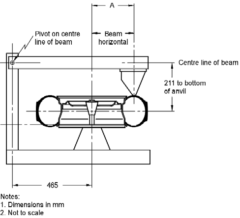
| DIMENSION “A” | ||||
|---|---|---|---|---|
| Wheel Size | For tires with a maximum permissible inflation pressure of other than 415 kPa (60 p.s.i.) | For tires with a maximum permissible inflation pressure of 415 kPa (60 p.s.i.) | ||
| In Millimetres | In Inches | In Millimetres | In Inches | |
| 19 in. | 330 | 13.0 | 305 | 12.0 |
| 18 in. | 318 | 12.5 | 290 | 11.4 |
| 17 in. | 305 | 12.0 | 269 | 10.6 |
| 16 in. | 292 | 11.5 | 251 | 9.9 |
| 15 in. | 279 | 11.0 | 239 | 9.4 |
| 14 in. | 267 | 10.5 | 226 | 8.9 |
| 13 in. | 254 | 10.0 | 213 | 8.4 |
| 12 in. | 241 | 9.5 | 201 | 7.9 |
| 11 in. | 229 | 9.0 | 188 | 7.4 |
| 10 in. | 216 | 8.5 | 175 | 6.9 |
| 500 mmFootnote for * | 311 | 12.25 | ||
| 475 mmFootnote for * | 298 | 11.75 | ||
| 450 mmFootnote for * | 286 | 11.25 | ||
| 425 mmFootnote for * | 273 | 10.75 | ||
| 415 mm | 292 | 11.5 | ||
| 400 mmFootnote for * | 260 | 10.25 | ||
| 390 mm | 279 | 11.0 | ||
| 370 mm | 254 | 10.0 | ||
| 365 mm | 248 | 9.75 | ||
| 345 mm | 239 | 9.25 | ||
| 340 mm | 229 | 9.0 | ||
| 320 mm | 216 | 8.5 | ||
Return to footnote *For CT tires only
FIGURE 2 — BEAD UNSEATING BLOCKFor tires with a maximum permissible inflation pressure of other than 415 kPa (60 p.s.i.)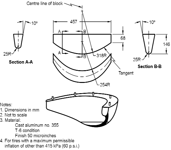 |
| Equivalent Dimensions | |
|---|---|
| In Millimetres | In Inches |
| 25 | 1.0 |
| 68 | 2.67 |
| 146 | 5.75 |
| 254 | 10.0 |
| 318 | 12.5 |
| 457 | 18.0 |
FIGURE 3 — BEAD UNSEATING BLOCKFor tires with a maximum permissible inflation pressure of 415 kPa (60 p.s.i.)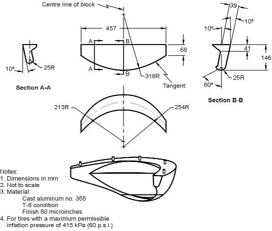 |
| Equivalent Dimensions | |
|---|---|
| In Millimetres | In Inches |
| 25 | 1.0 |
| 39 | 1.53 |
| 41 | 1.62 |
| 68 | 2.67 |
| 146 | 5.75 |
| 213 | 8.375 |
| 254 | 10.0 |
| 457 | 18.0 |
- SOR/2005-342, s. 7
- SOR/2008-258, s. 16
SCHEDULE V(Section 3, subsection 6(2) and paragraph 14(1)(a))Safety Standard 119 for Certain Tires Other than Passenger Car Tires
General
1 (1) Every tire of a particular size designation and type shall
(a) be designed to fit each rim specified for a tire of that size designation and type in a tire and rim document;
(b) have load ratings and corresponding tire inflation pressures for a tire of that size designation and type as specified in a tire and rim document; and
(c) subject to subsection (2), have a maximum load rating that is not less than the maximum load rating specified for a tire of that size designation and type in a tire and rim document.
(2) Where publication referred to in subsection 7(2) of these Regulations sets out more than one maximum load rating for a tire of a particular size designation and type, the required maximum load rating shall not be less than the lowest of the maximum load ratings set out in the publication.
Tread Wear Indicators
2 (1) Subject to subsection (3), every tire that has a rim diameter of 304.8 mm (12 in.) or more shall incorporate at least six treadwear indicators, spaced approximately equally around the circumference of the tire, in such a manner that the indicators will provide visible indication where the tire has worn to a tread depth of 1.6 mm (1/16 in.).
(2) Subject to subsection (3), every tire that has a rim diameter of less than 304.8 mm (12 in.) shall incorporate at least three treadwear indicators, spaced approximately equally around the circumference of the tire, in such a manner that the indicators will provide visible indication where the tire has worn to a tread depth of 1.6 mm (1/16 in.).
(3) Every motorcycle tire shall incorporate at least three treadwear indicators, spaced approximately equally around the circumference of the tire, in such a manner that the indicators will provide visible indication where the tire has worn to a tread depth of 0.8 mm (1/32 in.).
Rules Respecting Testing
3 For the purpose of testing, in accordance with subsections 5(2), 6(2) and 7(2), the strength, endurance and high speed performance of a tire, a new tire shall be used for each test.
4 Before being subjected to the tire endurance test set out in subsection 6(2) or the high speed performance test set out in subsection 7(2), a tire of a particular size designation and type shall have no visible evidence of tread separation, sidewall separation, ply separation, cord separation, innerliner separation, bead separation, chunking, broken cords, cracking or open splices.
Tire Strength
5 (1) Where a tire is tested for strength in accordance with subsection (2), the tire shall meet the applicable minimum static breaking energy values set out in Table I.
(2) The strength of a tire shall be tested by
(a) mounting the tire on a test rim and inflating it to the inflation pressure corresponding to the maximum single load as moulded onto or into the tire or, where both a maximum dual load and a maximum single load are marked on the tire, corresponding to the maximum dual load so marked;
(b) conditioning the assembled tire and rim at room temperature for at least three hours and then adjusting the inflation pressure of the conditioned tire to the tire inflation pressure referred to in paragraph (a);
(c) forcing, at a rate of 50.8 mm/min (2 in./min) perpendicularly into a test point located on a tread rib of the tire that is as near to the centreline of the tread as possible, a cylindrical steel plunger that has a hemispherical end and has a diameter specified in Table I for that class of tire;
(d) recording the force that was applied to the cylindrical steel plunger and the distance it moved from the point at which the pressure was applied to the point it reached either immediately before puncturing the tire or immediately before reaching the rim if the tire was not punctured,
(i) at five test points equally spaced around the circumference of the tire, where the tire is designed to fit a rim having a diameter greater than 304.8 mm (12 in.), or
(ii) at three test points equally spaced around the circumference of the tire, where the tire is designed to fit a rim having a diameter of 304.8 mm (12 in.) or less;
(e) computing the static breaking energy values at each test point at which the cylindrical steel plunger was forced into the tread rib by using the force and distance values recorded pursuant to paragraph (d) in the formula
W = (F × D ) ÷ 2
where
- W
- is the static breaking energy, expressed in joules (inch-pounds),
- F
- is the force, expressed in newtons (pounds), and
- D
- is the distance, expressed in metres (inches); and
(f) determining the static breaking energy value for the tire by computing the average of the values obtained pursuant to paragraph (e).
Tire Endurance
6 (1) Where a tire is tested for endurance in accordance with subsection (2), the tire shall
(a) at the end of the test, have
(i) no visible evidence of tread separation, sidewall separation, ply separation, cord separation, innerliner separation, bead separation, chunking, broken cords, cracking or open splices, and
(ii) a tire inflation pressure that is not less than the tire inflation pressure at the beginning of the test; and
(b) meet the applicable requirements for endurance set out in subsection (2) where tested on a test wheel either alone or simultaneously with up to five other tires.
(2) The tire endurance test shall be performed by
(a) mounting the tire on a test rim and inflating it to the inflation pressure corresponding to the maximum single load rating as marked on the sidewall;
(b) conditioning the assembled tire and rim at 38°C ± 3°C (100°F ± 5°F) for at least three hours and then adjusting the inflation pressure of the conditioned tire to that referred to in paragraph (a);
(c) mounting the assembled tire and rim on a test axle and pressing the tread of the tire against a flat-faced steel test wheel that is 1 707.6 mm (67.23 in.) in diameter and at least as wide as the section width of the tire;
(d) maintaining the air surrounding the test area at 38°C ± 3°C (100°F ± 5°F);
(e) running the tire for periods of 7 hours, 16 hours and 24 hours, under the test load and at the test wheel speed for the particular period as specified in Table II, without any adjustment to the inflation pressure of the tire;
(f) measuring the inflation pressure of the tire immediately after running it for the total number of hours required by paragraph (e); and
(g) deflating the tire, removing it from the rim after allowing it to cool and inspecting it for visible evidence of tread separation, sidewall separation, ply separation, cord separation, innerliner separation, bead separation, chunking, broken cords, cracking or open splices.
High Speed Performance
7 (1) Where a motorcycle tire or a tire that is designed to fit a rim having a diameter of 368.3 mm (14.5 in.) or less and that has a load range designation of “A”, “B”, “C” or “D” moulded into or onto the sidewalls in accordance with subparagraph 10(1)(a)(viii) of these Regulations, other than a tire having a speed restriction of 88.5 km/h (55 m.p.h.) or less moulded into or onto the sidewalls in accordance with subparagraph 10(1)(a)(iii) of these Regulations, is subjected to the high speed performance test in accordance with subsection (2), the tire shall
(a) at the end of the test, have
(i) no visible evidence of tread separation, sidewall separation, ply separation, cord separation, innerliner separation, bead separation, chunking, broken cords, cracking or open splices, and
(ii) a tire inflation pressure that is not less than the tire inflation pressure at the beginning of the test; and
(b) meet the requirement of the high speed performance test referred to in subsection (2) where tested on a test wheel alone or simultaneously with not more than five other tires.
(2) The high speed performance test shall be performed by
(a) mounting the tire on a test rim and inflating it to the inflation pressure corresponding to the maximum single load rating as marked on the sidewall;
(b) conditioning the assembled tire and rim at 38°C ± 3°C (100°F ± 5°F) for at least three hours and then adjusting the inflation pressure of the conditioned tire to that referred to in paragraph (a);
(c) mounting the assembled tire and rim on a test axle and applying a force on the tire of 88 per cent of the maximum single load rating as marked on the sidewall and pressing the tread of the tire against a flat-faced steel test wheel 1 707.6 mm (67.23 in.) in diameter and at least as wide as the section width of the tire;
(d) running the tire for two hours at a test wheel speed of 80 km/h (50 m.p.h.) with the force described in paragraph (c) applied to it;
(e) allowing the tire to cool to 38°C ± 3°C (100°F ± 5°F) and then adjusting the inflation pressure of the tire to that referred to in paragraph (a);
(f) running the tire, with the force described in paragraph (c) applied to it, for 30 minutes at each of the following test wheel speeds, namely, 121 km/h (75 m.p.h.), 129 km/h (80 m.p.h.) and 137 km/h (85 m.p.h.);
(g) measuring the inflation pressure of the tire immediately after running it for the total number of minutes required by paragraph (f); and
(h) deflating the tire, removing it from the rim after allowing it to cool and inspecting it for visible evidence of tread separation, sidewall separation, ply separation, cord separation, innerliner separation, bead separation, chunking, broken cords, cracking or open splices.
TABLE I
Plunger Diameter and Minimum Static Breaking Energy Values: Joules (Inch-Pounds)
| All Motorcycle Tires | Tubeless and tube type tires that fit a rim diameter of 304.8 mm (12 in.) or less | All light truck tires and tubeless tires that fit a rim diameter of 444.5 mm (17.5 in.) or less but greater than 304.8 mm (12 in.) | Tube type tires that fit a rim diameter of greater than 304.8 mm (12 in.), up to and including Load Range F | Tubeless tires that fit a rim diameter of greater than 444.5 mm (17.5 in.), up to and including Load Range F | Tube type tires that fit a rim diameter greater than 304.8 mm (12 in.) and greater than Load Range F | Tubeless tires that fit a rim diameter greater than 444.5 mm (17.5 in.) and greater than Load Range F | |
|---|---|---|---|---|---|---|---|
| Plunger Diameter mm (in.) | 7.94 (5/16) | 19.1 (3/4) | 19.1 (3/4) | 31.8 (1 1/4) | 31.8 (1 1/4) | 38.1 (1 1/2) | 38.1 (1 1/2) |
| Minimum static breaking energy in joules (inch-pounds) for the applicable load range: | |||||||
| A | 17 (150) | 68 (600) | 226 (2,000) | — | — | — | — |
| B | 34 (300) | 136 (1,200) | 294 (2,600) | — | — | — | — |
| C | 45 (400) | 203 (1,800) | 362 (3,200) | 768 (6,800) | 576 (5,100) | — | — |
| D | — | 271 (2,400) | 514 (4,550) | 893 (7,900) | 734 (6,500) | — | — |
| E | — | 339 (3,000) | 576 (5,100) | 1,412 (12,500) | 972 (8,600) | — | — |
| F | — | 407 (3,600) | 644 (5,700) | 1,785 (15,800) | 1,412 (12,500) | — | — |
| G | — | — | 712 (6,300) | — | — | 2,282 (20,200) | 1,695 (15,000) |
| H | — | — | 768 (6,800) | — | — | 2,599 (23,000) | 2,090 (18,500) |
| J | — | — | — | — | — | 2,825 (25,000) | 2,203 (19,500) |
| L | — | — | — | — | — | 3,051 (27,000) | — |
| M | — | — | — | — | — | 3,220 (28,500) | — |
| N | — | — | — | — | — | 3,390 (30,000) | — |
NOTE: For rayon cord tires, applicable energy values are 60 per cent of those in the Table.
TABLE II
Endurance Test Schedule
| Description | Load range | Test Wheel Speed (r.p.m.) | Test Load: Percentage of maximum single load rating as marked on sidewall of tire | Total Test Revolutions (thousands) | |||
|---|---|---|---|---|---|---|---|
I 7 hrs. | II 16 hrs. | III 24 hrs. | |||||
| Speed-restricted service | |||||||
| km/h | m.p.h | ||||||
| 88.5 | 55 | All | 125 | 66 | 84 | 101 | 352.5 |
| 80.5 | 50 | C, D | 150 | 75 | 97 | 114 | 423.0 |
| 80.5 | 50 | E, F, G | 100 | 66 | 84 | 101 | 282.0 |
| 80.5 | 50 | H, J, L | 100 | 66 | 84 | 101 | 282.0 |
| 56.3 | 35 | All | 75 | 66 | 84 | 101 | 211.0 |
| Motorcycle | All | 250 | 100Footnote for TABLE II Endurance Test Schedule(1) | 108Footnote for TABLE II Endurance Test Schedule(2) | 117 | 510.0 | |
| All others | A, B, C, D | 250 | 75Footnote for TABLE II Endurance Test Schedule(1) | 97Footnote for TABLE II Endurance Test Schedule(2) | 114 | 510.0 | |
| E | 200 | 70 | 88 | 106 | 564.0 | ||
| F | 200 | 66 | 84 | 101 | 564.0 | ||
| G | 175 | 66 | 84 | 101 | 493.5 | ||
| H, J, L, N | 150 | 66 | 84 | 101 | 423.0 | ||
Return to footnote (1)4 hours for tires subject to high speed requirements
Return to footnote (2)6 hours for tires subject to high speed requirements
SCHEDULE VI(Subsection 7(1))Address
1 The address of the Minister of Transport referred to in subsection 7(1) of these Regulations is
Minister of Transport
c/o
Road Safety and Motor Vehicle Regulation DirectorateDepartment of Transport
Transport Canada Building
Place de Ville
Ottawa, Ontario
K1A 0N5
SCHEDULE VII(Subsection 13(3))
Declaration of Importation for Exhibition, Demonstration, Evaluation or Testing Purposes
1 Name of the manufacturer of the tire:
2 Name of the person importing the tire:
3 The brand name, type and size designation of the tire:
4 The purpose of the importation:
I, the undersigned, (Authorized representative), declare that the information set out in this declaration is true and that
(a) the tire will be used in Canada solely for purposes of exhibition, demonstration, evaluation or testing, pursuant to paragraph 7(1)(a) of the Motor Vehicle Safety Act; and
(b) the tire will remain in Canada for not longer than one year or such other period as the Minister specifies.Footnote *
Return to footnote *Note: Subsection 7(5) of the Motor Vehicle Safety Act prohibits a person who signs a declaration referred to in paragraph 7(1)(a) of the Act to use or dispose of a tire that is the subject of the declaration other than in accordance with the terms of the declaration.
Signature of authorized representativeDate
- SOR/95-536, s. 9(F)
- Date modified: