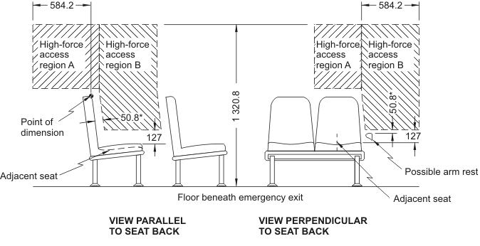
adjacent seat means a designated seating position so located that a portion of its occupant space is not more than 25.4 cm from an emergency exit for a distance of at least 38.1 cm measured horizontally and parallel to the emergency exit; (siège adjacent)
adjustment hardware
adjustment hardware means hardware designed for adjusting the size of a seat belt assembly to fit the user, including such hardware as may be integral with a buckle, a retractor or attachment hardware; (pièces de réglage)
agricultural commodity trailer
agricultural commodity trailer[Repealed, SOR/99-357, s. 1]
aiming reference plane
aiming reference plane[Repealed, SOR/96-366, s. 1]
air bag
air bag means an inflatable automatic occupant protection system that may be deployed when a collision occurs; (sac gonflable)
air brake system
air brake system means a brake system that uses air as a medium for transmitting pressure or force from the driver control to the service brake, including an air-over-hydraulic brake subsystem, but does not include a system that uses compressed air or vacuum only to assist the driver in applying muscular force to hydraulic or mechanical components; (système de freinage à air comprimé)
all-terrain vehicle
all-terrain vehicle means a wheeled or tracked vehicle, other than a snowmobile or work vehicle, designed primarily for recreational use or for the transportation of property or equipment exclusively on undeveloped road rights of way, marshland, open country or other unprepared surfaces; (véhicule tout terrain)
ambient temperature
ambient temperature means the surrounding air temperature measured at such a distance from a vehicle under test that the temperature is not significantly affected by heat from the vehicle; (température ambiante)
American specifications vehicle
American specifications vehicle[Repealed, SOR/95-147, s. 1]
ANSI
ANSI means the American National Standards Institute; (ANSI)
ANS Z26
ANS Z26[Repealed, SOR/94-717, s. 1]
ANSI Z26 Safety Code — 1990
ANSI Z26 Safety Code — 1990 means the American National Standard for Safety Glazing Materials for Glazing Motor Vehicles and Motor Vehicle Equipment Operating on Land Highways — Safety Code, Standard ANSI/SAE Z26.1 — 1990, published November 1990 and reprinted February 1992. (code de sécurité ANSI Z26 — 1990)
ANSI Z26 Safety Standard — 1996
ANSI Z26 Safety Standard — 1996 means the American National Standard for Safety Glazing Materials for Glazing Motor Vehicles and Motor Vehicle Equipment Operating on Land Highways — Safety Standard, Standard ANSI/SAE Z26.1-1996, published on August 11,1997. (norme de sécurité ANSI Z26 — 1996)
anthropomorphic test device
anthropomorphic test device means, except in section 202 of Schedule IV, a representation of a human being used in the measurement of the conditions that a human being would experience in a vehicle when the vehicle is subjected to approved test methods; (dispositif anthropomorphe d’essai)
antilock brake system
antilock brake system or ABS means the portion of a service brake system that automatically controls the degree of rotational wheel slip during braking by
(a) sensing the rate of angular rotation of the wheels,
(b) transmitting signals regarding the rate of wheel angular rotation to one or more controlling devices that interpret those signals and generate responsive controlling output signals, and
(c) transmitting those controlling signals to one or more modulators that adjust brake actuating forces in response to those signals; (dispositif de frein antiblocage ou ABS)
antilock system
antilock system[Repealed, SOR/97-200, s. 1]
antique reproduction vehicle
antique reproduction vehicle means a vehicle that is designed to be a scaled reproduction of an antique vehicle and
(a) may contain contemporary design components,
(b) has a motor that produces 8 kW (10.73 bhp) or less,
(c) is intended for use exclusively in parades, exhibitions and demonstrations, and
(d) bears a label, permanently affixed in a conspicuous position, stating that the vehicle is not to be used for public transportation, but is intended for use in parades, exhibitions and demonstrations; (réplique d’ancien modèle)
antique vehicle
antique vehicle means a vehicle more than 30 years old that, when restored to a condition comparable to that on the date of its manufacture, retains the original components or incorporates replacement components with original design characteristics; (ancien modèle)
approved
approved means approved by the Minister; (approuvé)
armour
armour[Repealed, SOR/2007-180, s. 1]
assembler
assembler[Repealed, SOR/95-147, s. 1]
ASTM
ASTM means the American Society for Testing Materials; (ASTM)
attachment hardware
attachment hardware means the hardware designed for securing the webbing of a seat belt assembly to a vehicle; (pièces de fixation)
automatic-locking retractor
automatic-locking retractor means a retractor incorporating adjustment hardware that has a positive self-locking mechanism that is capable, when locked, of withstanding restraint forces; (rétracteur autobloquant)
automatic occupant protection system
automatic occupant protection system means a protective restraining system for an occupant of a vehicle that does not require any deliberate action on the part of the occupant to be activated where that occupant enters, occupies or leaves the vehicle; (dispositif automatique de protection de l’occupant)
auto transporter
auto transporter means a truck and a trailer designed for use in combination to transport motor vehicles where the truck is designed to carry cargo other than at the fifth wheel and that cargo is to be loaded only by means of the trailer; (porte-autos)
back door
back door means a door or door system on the back of a motor vehicle through which passengers can enter or leave the vehicle or cargo can be loaded or unloaded, but does not include
(a) a trunk lid, or
(b) a door or window that is composed entirely of glazing material and whose latches or hinge systems are attached directly to the glazing material; (porte arrière)
backup system
backup system means a portion of a service brake system, such as a pump, that automatically supplies energy in the event of a primary brake power source failure; (système de secours)
battery charging indicator
battery charging indicator means a device showing whether the battery is being charged or discharged; (indicateur de charge)
battery charging tell-tale
battery charging tell-tale means a signal that, when alight, indicates that the battery is not being charged; (témoin de charge)
beam contributor
beam contributor[Repealed, SOR/96-366, s. 1]
blister
blister[Repealed, SOR/2007-180, s. 1]
body type
body type means the general configuration or shape of a vehicle distinguished by the number of doors or windows, cargo carrying features, the roofline (e.g., sedan, fastback, hatchback) or other characteristics; (type de carrosserie)
bonded construction sealed beam headlamp
bonded construction sealed beam headlamp[Repealed, SOR/96-366, s. 1]
brake hose end fitting[Repealed, SOR/2007-180, s. 1]
brake power assist unit
brake power assist unit means a device installed in a hydraulic brake system that reduces the amount of muscular force that a driver must apply to actuate the system, and that, if inoperative, does not prevent the driver from braking the vehicle by a continued application of muscular force on the service brake control; (unité d’assistance de frein)
brake power unit
brake power unit means a device installed in a brake system that provides the energy required to actuate the brakes, either directly or indirectly, through an auxiliary device, with driver action consisting only of modulating the energy application level; (unité de servo-frein)
braking interval
braking interval means the distance measured from the point of initiation of one brake application to the point of initiation of the next brake application; (intervalle de freinage)
buckle
buckle means a quick-release connector that secures a person in a seat belt assembly or a built-in restraint system; (attache)
built-in booster cushion
built-in booster cushion[Repealed, SOR/2013-117, s. 1]
built-in booster seat
built-in booster seat means a device that
(a) is an integral part of a vehicle seat, and
(b) is designed to seat a person whose mass is at least 18 kg, to ensure that the seat belt assembly fits properly; (siège d’appoint intégré)
built-in child restraint system
built-in child restraint system[Repealed, SOR/2013-117, s. 1]
built-in dual-purpose restraint system
built-in dual-purpose restraint system[Repealed, SOR/2013-117, s. 1]
built-in restraint system
built-in restraint system means a device that
(a) is an integral part of a vehicle seat, and
(b) is designed to restrain only a person whose mass is more than 10 kg but not more than 41 kg; (ensemble intégré de retenue)
bus
bus means a vehicle having a designated seating capacity of more than 10, but does not include a trailer or a vehicle imported temporarily for special purposes; (autobus)
bus trailer
bus trailer means a vehicle having a designated seating capacity of more than 10 and designed primarily to be drawn behind another vehicle; (remorque-autobus)
C-dolly
C-dolly means a trailer converter dolly that is equipped with a single axle that is self-steering and with a coupling that is so designed that when the trailer converter dolly is coupled to a towing trailer, the trailer converter dolly cannot pivot horizontally with respect to the towing trailer; (chariot de conversion de type C)
cable reel trailer
cable reel trailer means a vehicle designed to be drawn behind another vehicle for the exclusive purpose of carrying a drum or reel of cable; (chariot dérouleur)
cargo-carrying capacity
cargo-carrying capacity means the mass that is equal to or less than the result obtained by subtracting from the gross vehicle weight rating the sum of
(a) the unloaded vehicle mass,
(b) the product obtained by multiplying the designated seating capacity by 54 kg, in the case of a school bus, or by 68 kg, in any other case, and
(c) in the case of a vehicle having living or sanitary accommodations, the mass of its fresh water, hot water and propane tanks, but not its waste water tanks, when full; (capacité de chargement)
chassis-cab
chassis-cab means an incomplete vehicle, other than an incomplete trailer, with a completed occupant compartment that requires only the addition of a cargo-carrying surface, work-performing equipment or a load-bearing component to perform its intended functions. (châssis-cabine)
check digit
check digit means a single number or the letter “X” used to verify the accuracy of the transcription of the vehicle identification number; (unité de contrôle)
child
child means a person whose mass is more than 10 kg and not more than 30 kg; (enfant)
child restraint system
child restraint system[Repealed, SOR/98-160, s. 1]
chipping
chipping[Repealed, SOR/2007-180, s. 1]
CMVSS
CMVSS is an abbreviation for Canada Motor Vehicle Safety Standard; (NSVAC)
competition car
competition car[Repealed, SOR/2000-182, s. 1]
competition motorcycle
competition motorcycle[Repealed, SOR/2000-182, s. 1]
competition snowmobile
competition snowmobile[Repealed, SOR/2000-182, s. 1]
competition vehicle
competition vehicle means a vehicle that is designed for use exclusively in closed-course competition and
(a) bears a label affixed by the manufacturer stating, in both official languages, that the vehicle is a competition vehicle and is for use exclusively in closed-course competition, or
(b) is accompanied by a signed declaration clearly indicating that the vehicle is a competition vehicle and is for use exclusively in closed-course competition; (véhicule de compétition)
completed vehicle
completed vehicle means a vehicle that needs no further manufacturing operations to perform its intended function, other than the addition of readily attachable components, such as mirrors or tire and rim assemblies, or minor finishing operations such as painting; (véhicule complet)
compliance label
compliance label means the label required to be applied to a completed vehicle under section 6 or 6.6; (étiquette de conformité)
compressed natural gas
compressed natural gas or CNG means natural gas, composed predominantly of methane, compressed at pressures up to 20 680 kPa (3,000 psi); (gaz naturel comprimé or GNC)
contactable surface
contactable surface[Repealed, SOR/98-160, s. 1]
control
control means the part of a device that enables the driver to bring about a change in the state or functioning of a vehicle or vehicle component; (commande)
convertible
convertible means a vehicle that has an A-pillar or windshield peripheral support, the upper portion of which is not joined by a fixed rigid structure to the B-pillar or other rear roof support to the rear of the B-pillar; (décapotable)
CSA
CSA means the Canadian Standards Association; (CSA)
curb mass
curb mass means the mass of a vehicle with standard equipment and carrying its maximum capacity of fuel, oil and coolant and includes the mass of any air-conditioning equipment on the vehicle and the amount by which the mass of any optional engine with which the vehicle is equipped exceeds the mass of the standard engine; (masse à vide)
curb weight
curb weight means the weight of a vehicle with standard equipment and carrying its maximum capacity of fuel, oil and coolant and includes the weight of any air-conditioning equipment on the vehicle and the amount by which the weight of any optional engine with which the vehicle is equipped exceeds the weight of the standard engine; (poids à vide)
custom restraint system for disabled persons
custom restraint system for disabled persons[Repealed, SOR/98-160, s. 1]
cutaway chassis
cutaway chassis means an incomplete vehicle that has the back of the cab cut out for the intended installation of a structure that permits access from the driver’s area to the back of the vehicle; (châssis tronqué)
daytime running lamp
daytime running lamp means, for the purposes of section 108 of Schedule IV, a lamp used to improve the visibility of a vehicle when the vehicle is viewed from the front in daylight; (feu de jour)
demountable rim
demountable rim means a supporting member for a tire or tire and tube assembly, that does not have a permanently attached centre component; (jante amovible)
designated seating capacity
designated seating capacity means the designated seating capacity determined in accordance with section 2.3; (nombre désigné de places assises)
designated seating position
designated seating position means a location in a vehicle that is likely to be used as a seating position and that has a seating surface width of at least 330 mm; (place assise désignée)
disabled person
disabled person means a person who, for orthopaedic reasons or because of the person’s build or other physical characteristics, requires a vehicle that has been adapted to accommodate their disability; (personne handicapée)
disc wheel
disc wheel means a supporting member for a tire or tire and tube assembly, comprising a rim with a dish-shaped component that is permanently attached to the inner circumference of the rim; (roue à disque)
display
display means, except in section 101 of Schedule IV, an indicator, a tell-tale or an alphanumeric readout, or a collection of indicators, tell-tales and alphanumeric readouts, on the instrument panel of a vehicle; (affichage)
distributor
distributor[Repealed, SOR/95-147, s. 1]
driver
driver means the occupant of a vehicle seated immediately behind the steering control system; (conducteur)
driver-operated accelerator control system
driver-operated accelerator control system means all components of a vehicle, except the fuel metering device, that regulate engine speed in direct response to movement of the driver-operated control and that return the throttle to the idle position upon release of the driver-operated control; (système de commande d’accélération actionné par le conducteur)
ECE
ECE means the United Nations Economic Commission for Europe, Inland Transport Committee; (CEE)
effective projected luminous lens area
effective projected luminous lens area[Repealed, SOR/96-366, s. 1]
emergency brake
emergency brake means a mechanism designed to stop a vehicle after a failure of the service brake system; (frein de secours)
emergency-locking retractor
emergency-locking retractor means a retractor incorporating adjustment hardware that has a locking mechanism that is activated by vehicle acceleration, webbing movement in relation to the vehicle or other automatic action during an emergency, and is capable, when locked, of withstanding restraint forces; (rétracteur à blocage d’urgence)
emergency vehicle
emergency vehicle means any fire-fighting vehicle, ambulance, police vehicle or other vehicle that is used for the purpose of an emergency; (véhicule de secours)
enclosed motorcycle
enclosed motorcycle means a motorcycle that
(a) has steering handlebars that are completely constrained from rotating in relation to the axle of only one wheel in contact with the ground,
(b) is designed to travel on two wheels in contact with the ground,
(c) has a minimum driver’s seat height, when the vehicle is unladen, of 650 mm, and
(d) has a structure partially or fully enclosing the driver and passenger that is an integral part of the vehicle chassis; (motocyclette à habitacle fermé)
engine coolant temperature indicator
engine coolant temperature indicator means a device that presents information concerning the temperature of the coolant; (indicateur de température du liquide de refroidissement)
engine coolant temperature tell-tale
engine coolant temperature tell-tale means a signal that, when alight, indicates that the temperature of the engine coolant is above the normal engine running temperature prescribed by the manufacturer; (témoin de température du liquide de refroidissement)
engine type
engine type means a power source distinguished by the fuel utilized, number of cylinders, displacement, net power or other characteristics; (type de moteur)
ERBP
ERBP[Repealed, SOR/2007-180, s. 1]
final-stage manufacturer
final-stage manufacturer means a company that performs the manufacturing operations on an incomplete vehicle that turn the incomplete vehicle into a completed vehicle; (fabricant à l’étape finale)
fixed collision barrier
fixed collision barrier means a device that
(a) consists of
(i) a structure with a flat, vertical, unyielding impact surface that is of a size sufficient to ensure that no portion of a vehicle striking the surface projects or passes beyond the surface, and
(ii) a horizontal approach surface that does not impede vehicle motion during impact and that is of a size sufficient to ensure that a vehicle will be able to attain a stable attitude during its approach to the impact surface, and
(b) does not absorb any significant portion of the kinetic energy of a vehicle striking the impact surface; (barrière fixe pour essais de collision)
flash
flash means a cycle of automatic activation and deactivation of a lamp that continues until stopped either automatically or manually; (clignotement)
forward control configuration
forward control configuration means a configuration in which more than half of the engine length is rearward of the foremost point of the windshield base and the steering wheel hub is in the forward quarter of the vehicle length; (type à cabine avancée)
free length
free length[Repealed, SOR/2007-180, s. 1]
front outboard designated seating position
front outboard designated seating position means the driver’s designated seating position and the forwardmost right outboard designated seating position, but does not include a school bus passenger designated seating position; (place assise désignée extérieure avant)
fuel container
fuel container means one or more fuel containers with integral valving, pressure relief devices, tubing, hoses and mounting brackets; (réservoir de carburant)
fuel level indicator
fuel level indicator means a device that presents information concerning the amount of fuel in the tank; (indicateur de niveau de carburant)
fuel level tell-tale
fuel level tell-tale means a signal that, when alight, indicates that the fuel level is close to zero or that the vehicle is running on its fuel reserve; (témoin de niveau de carburant)
fuel metering device
fuel metering device means the carburetor, fuel injector, fuel distributor or fuel injection pump; (dispositif de dosage du carburant)
fuel spillage
fuel spillage means the fall, flow or run of fuel from a vehicle but does not include wetness resulting from capillary action; (écoulement de carburant)
fuel system
fuel system means all components used to store fuel or supply fuel to a vehicle engine; (circuit d’alimentation en carburant)
full trailer
full trailer, for the purposes of Technical Standards Document No. 121, Air Brake Systems, means a trailer, except a pole trailer, that is equipped with two or more axles that support the entire weight of the trailer and its load; (remorque complète)
gasoline
gasoline[Repealed, SOR/2002-187, s. 1]
glazing material manufacturer
glazing material manufacturer means a person engaged in the business of fabricating, laminating or tempering glazing material. (fabricant de vitrages)
grade
grade[Repealed, SOR/2007-180, s. 1]
gross axle weight rating
gross axle weight rating or GAWR means the value specified by the vehicle manufacturer as the load-carrying capacity of a single axle system, as measured at the tire-ground interfaces; (poids nominal brut sur l’essieu or PNBE)
gross vehicle weight rating
gross vehicle weight rating or GVWR means the value specified by the vehicle manufacturer as the loaded weight of a single vehicle; (poids nominal brut du véhicule or PNBV)
H-point
H-point means the mechanically hinged hip point of a manikin that simulates the actual pivot centre of the human torso and thigh, described in SAE Standard J826, Devices for Use in Defining and Measuring Vehicle Seating Accommodation (July 1995); (point H)
H-V axis
H-V axis means the characteristic axis of the light pattern of a lamp, passing through the centre of the light source, used as the direction of reference (H = 0°, V = 0°) for photometric measurements and for the design of the installation of a lamp on a vehicle; (axe H-V)
hardware
hardware, when used in relation to a seat belt assembly, means any metal or rigid plastic part; (pièces)
head impact area
head impact area means the area described in subsection 201(1) of Schedule IV; (zone d’impact de la tête)
headlamp
headlamp means, for the purposes of sections 108 and 108.1 of Schedule IV, a lamp used to illuminate the road and objects on the road ahead of the vehicle, but does not include a fog lamp or a supplementary driving lamp; (projecteur)
headlamp assembly
headlamp assembly means an assembly that consists of one or more headlamps, aiming devices, headlamp retaining components, electrical connectors and mounting brackets, and which may include a housing and one or more bulbs; (montage de projecteur)
head restraint
head restraint means a device that limits rearward angular displacement of the occupant’s head relative to their torso line; (appuie-tête)
hearse
hearse means a vehicle that contains only one row of occupant seats, is designed exclusively for transporting a body and casket and is equipped with features to secure a casket in place during the operation of the vehicle; (corbillard)
heavy duty vehicle
heavy duty vehicle[Repealed, SOR/2001-35, s. 1]
heavy hauler trailer
heavy hauler trailer means a trailer that has
(a) brake lines designed to adapt to separation or extension of the vehicle frame, or
(b) a body that consists of only a platform the primary cargo-carrying surface of which is not more than 101.6 cm (40 inches) above the ground in an unloaded condition, but may include sides that are designed for easy removal and a permanent front end structure; (remorque lourde)
high-pressure portion of the fuel system
high-pressure portion of the fuel system means, for a vehicle that uses LPG or CNG as a source of energy for its propulsion, all the components of the fuel system from and including the fuel container to, but not including, the first stage regulator; (partie haute pression du circuit d’alimentation en carburant)
hub
hub means a rotating member that provides for mounting of disc wheels; (moyeu)
hydraulic brake system
hydraulic brake system means a system that uses hydraulic fluid as a medium for transmitting force from a service brake control to the service brake, and that may incorporate a brake power assist unit or a brake power unit; (système de freinage hydraulique)
hydraulic system mineral oil
hydraulic system mineral oil[Repealed, SOR/2007-180, s. 1]
idle position
idle position means the position of the throttle at which it first comes in contact with an engine idle speed control appropriate for existing conditions according to the manufacturers’ recommendations respecting engine speed adjustments for a cold engine, air conditioning, emission control and throttle setting devices; (position de ralenti)
imported used vehicle
imported used vehicle[Repealed, SOR/92-173, s. 1]
importer
importer[Repealed, SOR/95-147, s. 1]
incomplete trailer
incomplete trailer means a vehicle, other than a vehicle imported temporarily for special purposes, that is capable of being drawn and that consists, at a minimum, of a chassis structure and suspension system but needs further manufacturing operations performed on it to become a completed vehicle; (remorque incomplète)
incomplete vehicle
incomplete vehicle means a vehicle
(a) other than a vehicle imported temporarily for special purposes, that is capable of being driven and that consists, at a minimum, of a chassis structure, power train, steering system, suspension system and braking system in the state in which those systems are to be part of the completed vehicle, but requires further manufacturing operations to become a completed vehicle, or
(b) that is an incomplete trailer; (véhicule incomplet)
incomplete vehicle manufacturer
incomplete vehicle manufacturer means a company that manufactures an incomplete vehicle by assembling components none of which, taken separately, constitutes an incomplete vehicle; (fabricant de véhicules incomplets)
indicator
indicator means the part of an instrument that shows the quantity of the physical characteristic that the instrument is designed to sense; (indicateur)
infant
infant means a person who is unable to walk unassisted and whose mass is not more than 10 kg; (bébé)
infant restraint system
infant restraint system[Repealed, SOR/98-160, s. 1]
information label
information label means the label required to be applied to an incomplete vehicle under section 6.2 or 6.4; (étiquette informative)
information readout display
information readout display[Repealed, SOR/93-31, s. 1]
initial brake temperature
initial brake temperature[Repealed, SOR/99-357, s. 1]
inspector
inspector[Repealed, SOR/95-147, s. 1]
integral headlamp aiming device
integral headlamp aiming device[Repealed, SOR/96-366, s. 1]
intermediate manufacturer
intermediate manufacturer means a company, other than an incomplete vehicle manufacturer or final-stage manufacturer, that performs manufacturing operations on an incomplete vehicle; (fabricant intermédiaire)
IRHD
IRHD[Repealed, SOR/2007-180, s. 1]
leaded gasoline
leaded gasoline means gasoline that contains more than
(a) 0.06 grams of lead per Imperial gallon (0.013 grams per litre), or
(b) 0.006 grams of phosphorous per Imperial gallon (0.0013 grams per litre); (essence au plomb)
light duty vehicle
light duty vehicle[Repealed, SOR/2001-35, s. 1]
lightly loaded vehicle weight
lightly loaded vehicle weight[Repealed, SOR/99-357, s. 1]
light source
light source[Repealed, SOR/96-366, s. 1]
light-truck tire
light-truck tire or LT tire means a tire designated by its manufacturer as primarily intended for use on lightweight trucks or multi-purpose passenger vehicles; (pneu pour camion léger)
limited-speed motorcycle
limited-speed motorcycle means a motorcycle that
(a) has steering handlebars that are completely constrained from rotating in relation to the axle of only one wheel in contact with the ground,
(b) has a maximum speed of 70 km/h or less,
(c) has a minimum driver’s seat height, when the vehicle is unladen, of 650 mm, and
(d) does not have a structure partially or fully enclosing the driver and passenger, other than that part of the vehicle forward of the driver’s torso and the seat backrest; (motocyclette à vitesse limitée)
line
line means the name that a manufacturer applies to a family of vehicles within a make that have a degree of commonality of body, chassis, cab type or other features of construction; (ligne)
liquefied petroleum gas
liquefied petroleum gas or LPG means a hydrocarbon product that meets National Standard of Canada CAN/CGSB-3.14-M88, Liquefied Petroleum Gas (Propane) (August 1988). (gaz de pétrole liquéfié ou GPL)
load divider dolly
load divider dolly means a trailer that consists of a trailer chassis and one or more axles, with no solid bed, body or container attached, and that is designed exclusively to support a portion of the load on a trailer or truck excluded from all the requirements of Technical Standards Document No. 121, Air Brake Systems; (chariot de répartition de charge)
load-limiter
load-limiter means a seat belt assembly component or seat belt assembly feature that controls tension on a seat belt to modulate the forces that are imparted to an occupant who is restrained by the seat belt assembly during a collision; (limiteur de charge)
lower connector system
lower connector system[Repealed, SOR/2013-117, s. 1]
lower universal anchorage system
lower universal anchorage system means a device, other than a vehicle seat belt, that is designed to secure the lower portion of a restraint system or booster seat to a vehicle and that transfers the load from the restraint system or booster seat and its occupant to the vehicle structure or a vehicle seat structure; (dispositif universel d’ancrages d’attaches inférieurs)
low-speed vehicle
low-speed vehicle means a vehicle, other than a restricted-use motorcycle or a vehicle imported temporarily for special purposes, that
(a) is designed for use primarily on streets and roads where access and the use of other classes of vehicles are controlled by law or agreement,
(b) travels on four wheels,
(c) is powered by an electric power train (an electric motor and, if present, a transmission) that is designed to allow the vehicle to attain a speed of 32 km/h but not more than 40 km/h in a distance of 1.6 km on a paved level surface,
(d) does not use fuel as an on-board source of energy, and
(e) has a GVWR of less than 1 361 kg; (véhicule à basse vitesse)
make
make means the name that a manufacturer applies to a group of vehicles; (marque)
manual seat belt assembly
manual seat belt assembly means, with respect to a Type 1 or Type 2 seat belt assembly, an assembly that requires a deliberate action on the part of the occupant of a vehicle to be activated; (ceinture de sécurité manuelle)
manufacturer
manufacturer[Repealed, SOR/95-147, s. 1]
master lighting switch
master lighting switch means a switch with one or more operational positions that controls the tail lamps, parking lamp, licence plate lamp, side marker lamps and headlamps and may control identification lamps and clearance lamps; (commutateur général d’éclairage)
maximum load
maximum load[Repealed, SOR/2008-258, s. 1]
maximum loaded vehicle mass
maximum loaded vehicle mass[Repealed, SOR/2008-258, s. 1]
maximum speed
maximum speed means, with respect to a motorcycle, the speed specified by the manufacturer as the highest speed that the motorcycle is capable of attaining, measured in accordance with section 5.3; (vitesse maximale)
minibike
minibike[Repealed, SOR/88-268, s. 1]
Minister
Minister means the Minister of Transport; (ministre)
mobile home
mobile home means a vehicle that is more than 102 inches in overall width and that is designed to be drawn behind another vehicle and to be used as a living or working accommodation unit; (maison roulante)
mobility-impaired occupant
mobility-impaired occupant[Repealed, SOR/2013-117, s. 1]
model
model means the name that a manufacturer applies to a family of vehicles of the same class, make, line, series and body type; (modèle)
model year
model year means the year used to designate a discrete vehicle model irrespective of the calendar year in which the vehicle was actually produced, so long as the period of such production is less than two years; (année de modèle)
moped
moped[Repealed, SOR/88-268, s. 1]
motorcycle
motorcycle means a vehicle that is of the subclasses enclosed motorcycle, open motorcycle, limited-speed motorcycle or motor tricycle, and
(a) is designed to travel on not more than three wheels in contact with the ground,
(b) has a minimum wheel rim diameter of 250 mm, and
(c) has a minimum wheelbase of 1 016 mm,
but does not include a power-assisted bicycle, a restricted-use motorcycle, a passenger car, a truck, a multi-purpose passenger vehicle, a competition vehicle, a vehicle imported temporarily for special purposes or a three-wheeled vehicle; (motocyclette)
motor driven cycle
motor driven cycle[Repealed, SOR/88-268, s. 1]
motor home
motor home means a multi-purpose passenger vehicle that is designed to provide temporary residential accommodations, as evidenced by the presence of at least four of the following:
(a) cooking facilities,
(b) a refrigerator or ice box,
(c) a self-contained toilet,
(d) a heating or air-conditioning system that can function independently of the vehicle engine,
(e) a potable water supply system that includes a faucet and sink, and
(f) a separate 110- to 125-V electric power supply or an LP gas supply; (autocaravane)
motor tricycle
motor tricycle means a motorcycle, other than an antique reproduction vehicle, that
(a) is designed to travel on three wheels that are in contact with the ground and symmetrically arranged in relation to the longitudinal median plane,
(b) has seating on which the driver and passenger must sit astride,
(c) has not more than four designated seating positions,
(d) has a GVWR of 1 000 kg or less,
(e) has a maximum speed of more than 70 km/h, and
(f) does not have a structure partially or fully enclosing the driver and passenger, other than that part of the vehicle forward of the driver’s torso and the seat backrest; (tricycle à moteur)
Motor Vehicle Safety Test Methods
Motor Vehicle Safety Test Methods[Repealed, SOR/97-141, s. 1]
Motor Vehicle Safety Test Methods, section 106, “Brake Hoses”
Motor Vehicle Safety Test Methods, section 106, “Brake Hoses”[Repealed, SOR/2007-180, s. 1]
Motor Vehicle Safety Test Methods, section 116, “Hydraulic Brake Fluid”
Motor Vehicle Safety Test Methods, section 116, “Hydraulic Brake Fluid”[Repealed, SOR/95-536, s. 7]
Motor Vehicle Safety Test Methods, section 116, “Hydraulic Brake Fluids”
Motor Vehicle Safety Test Methods, section 116, “Hydraulic Brake Fluids”[Repealed, SOR/2007-180, s. 1]
multifunction school activity bus
multifunction school activity bus means a school bus that is designed to pick up and drop off students under circumstances in which there is no need to control traffic. (autobus multifonction pour les activités scolaires)
multiple compartment lamp
multiple compartment lamp[Repealed, SOR/96-366, s. 1]
multiple lamp arrangement
multiple lamp arrangement[Repealed, SOR/96-366, s. 1]
multi-purpose passenger vehicle
multi-purpose passenger vehicle means a vehicle having a designated seating capacity of 10 or less that is constructed either on a truck chassis or with special features for occasional off-road operation, but does not include an air cushion vehicle, an all-terrain vehicle, a golf cart, a low-speed vehicle, a passenger car, a three-wheeled vehicle, a truck or a vehicle imported temporarily for special purposes; (véhicule de tourisme à usages multiples)
non-locking retractor
non-locking retractor means a retractor that does not have a locking mechanism, from which the webbing can be extended to substantially its full length by a small external force, that provides no adjustment for assembly length and that need not be capable of sustaining restraint forces at maximum webbing extension; (rétracteur sans blocage)
normal load
normal load[Repealed, SOR/2008-258, s. 1]
normal occupants’ mass
normal occupants’ mass[Repealed, SOR/2008-258, s. 1]
occupant
occupant means a person or manikin seated in a vehicle and, unless otherwise specified, means a person or manikin having the dimensions and weight of a 95th percentile adult male; (occupant)
occupant compartment air space
occupant compartment air space[Repealed, SOR/2007-180, s. 1]
occupant distribution
occupant distribution[Repealed, SOR/2008-258, s. 1]
occupant space
occupant space means the space directly above the seat and footwell, bounded vertically by the ceiling and horizontally by the normally positioned seat back and the nearest obstruction of occupant motion in the direction the seat faces; (espace d’occupant)
off-road motorcycle
off-road motorcycle[Repealed, SOR/88-268, s. 1]
oil pressure indicator
oil pressure indicator means a device that presents information concerning the pressure of the oil in the engine lubrication circuit; (indicateur de pression d’huile)
oil pressure tell-tale
oil pressure tell-tale means a signal that, when alight, indicates that the oil pressure in the engine lubrication circuit is below the normal operating limit prescribed by the manufacturer; (témoin de pression d’huile)
on-highway vehicle
on-highway vehicle[Repealed, SOR/2004-250, s. 1]
on-off-highway vehicle
on-off-highway vehicle[Repealed, SOR/2004-250, s. 1]
open-body type vehicle
open-body type vehicle means a vehicle that has no top over the occupant compartment or that has a top over the occupant compartment that can be installed or removed by the operator of the vehicle; (véhicule de type ouvert)
open motorcycle
open motorcycle means a motorcycle that
(a) has steering handlebars that are completely constrained from rotating in relation to the axle of only one wheel in contact with the ground,
(b) is designed to travel on two wheels in contact with the ground or, if the wheels are asymmetrically arranged in relation to the longitudinal median plane, three wheels in contact with the ground,
(c) has a minimum driver’s seat height, when the vehicle is unladen, of 650 mm,
(d) has a maximum speed of more than 70 km/h, and
(e) does not have a structure partially or fully enclosing the driver and passenger, other than that part of the vehicle forward of the driver’s torso and the seat backrest; (motocyclette sans habitacle fermé)
optically combined lamps
optically combined lamps means, for the purposes of section 108 of Schedule IV, lamps that have
(a) two or more separate light sources or a single light source that operates in different ways,
(b) one lens totally or partly in common, and
(c) a common lamp body; (feux combinés optiquement)
optional item
optional item[Repealed, SOR/2008-258, s. 1]
outboard designated seating position
outboard designated seating position means a designated seating position where a longitudinal vertical plane tangent to the outboard side of the seat cushion is less than 305 mm from the innermost point on the inside surface of the vehicle, which point is located vertically between the seating reference point and the shoulder reference point and longitudinally between the front and rear edges of the seat cushion; (place assise désignée extérieure)
overall width
overall width means the nominal design dimension of the widest part of the vehicle with doors and windows closed and wheels in the straight ahead position, exclusive of signal lamps, marker lamps, outside rearview mirrors, flexible fender extensions and mud flaps; (largeur hors tout)
parking brake
parking brake means a mechanism designed to prevent the movement of a stationary vehicle; (frein de stationnement)
parking mechanism
parking mechanism[Repealed, SOR/99-357, s. 1]
passenger car
passenger car means a vehicle having a designated seating capacity of 10 or less, but does not include an all-terrain vehicle, a competition vehicle, a low-speed vehicle, a multi-purpose passenger vehicle, an antique reproduction vehicle, a motorcycle, a truck, a trailer, a vehicle imported temporarily for special purposes or a three-wheeled vehicle; (voiture de tourisme)
passenger car tire
passenger car tire means a tire intended for use on passenger cars, multi-purpose passenger vehicles and trucks with a GVWR of 4 536 kg or less; (pneu pour voiture de tourisme)
passive occupant protection
passive occupant protection[Repealed, SOR/93-5, s. 1]
passive restraint system
passive restraint system[Repealed, SOR/93-5, s. 1]
pelvic restraint
pelvic restraint means a seat belt assembly or portion thereof intended to restrain movement of the pelvis; (ceinture sous-abdominale)
permanently attached hose end fitting
permanently attached hose end fitting[Repealed, SOR/2007-180, s. 1]
plant of manufacture
plant of manufacture means the plant at which the manufacturer affixes the vehicle identification number; (usine de construction)
pole trailer
pole trailer means a vehicle designed to be drawn behind another vehicle by means of a reach or pole, or by being boomed or otherwise secured to the towing vehicle, for the purpose of transporting poles, pipes, structural members or other long or irregularly shaped loads capable generally of sustaining themselves as beams between the supporting connections; (remorque pour charges longues)
power-assisted bicycle
power-assisted bicycle means a vehicle that:
(a) has steering handlebars and is equipped with pedals,
(b) is designed to travel on not more than three wheels in contact with the ground,
(c) is capable of being propelled by muscular power,
(d) has one or more electric motors that have, singly or in combination, the following characteristics:
(i) it has a total continuous power output rating, measured at the shaft of each motor, of 500 W or less,
(ii) if it is engaged by the use of muscular power, power assistance immediately ceases when the muscular power ceases,
(iii) if it is engaged by the use of an accelerator controller, power assistance immediately ceases when the brakes are applied, and
(iv) it is incapable of providing further assistance when the bicycle attains a speed of 32 km/h on level ground,
(e) bears a label that is permanently affixed by the manufacturer and appears in a conspicuous location stating, in both official languages, that the vehicle is a power-assisted bicycle as defined in this subsection, and
(f) has one of the following safety features,
(i) an enabling mechanism to turn the electric motor on and off that is separate from the accelerator controller and fitted in such a manner that it is operable by the driver, or
(ii) a mechanism that prevents the motor from being engaged before the bicycle attains a speed of 3 km/h; (bicyclette assistée)
power-operated roof panel
power-operated roof panel[Repealed, SOR/2007-180, s. 1]
power-operated roof panel system
power-operated roof panel system means a panel or panels in the roof of a vehicle that move on slides or hinges, the opening or closing of which is operated by a power source within the vehicle, but does not include a convertible top system; (système de toit ouvrant à commande électrique)
prescribed class
prescribed class means a class of vehicle listed in Schedule III or the class of incomplete vehicle prescribed under subsection 4(1.1); (catégorie réglementaire)
prime glazing material manufacturer
prime glazing material manufacturer[Repealed, SOR/2002-187, s. 1]
production options mass
production options mass[Repealed, SOR/2008-258, s. 1]
production restraint system for disabled persons
production restraint system for disabled persons[Repealed, SOR/98-160, s. 1]
pulpwood trailer
pulpwood trailer[Repealed, SOR/99-357, s. 1]
push-out window
push-out window means a vehicle window designed to open outward to provide for emergency egress; (fenêtre basculante)
readily removable window
readily removable window means a window that can be quickly and completely removed from a vehicle without tools and, in the case of a bus having a GVWR of more than 4 535.9 kg (10,000 pounds), shall include a push-out window and a window mounted in an emergency exit that can be manually pushed out of its location in the vehicle without the use of tools, regardless of whether the window remains hinged at one side to the vehicle; (fenêtre amovible)
rear outboard designated seating position
rear outboard designated seating position means any outboard designated seating position that is to the rear of a front outboard designated seating position, but does not include a designated seating position adjacent to a walkway located between the seat and the side of the vehicle interior that is designed to allow access to more rearward seating positions; (place assise désignée extérieure arrière)
recreational trailer
recreational trailer means a trailer designed to provide temporary living accommodation for travel, vacation or recreational use; (remorque de camping)
replaceable bulb headlamp
replaceable bulb headlamp[Repealed, SOR/96-366, s. 1]
restraint system for disabled persons[Repealed, SOR/98-160, s. 1]
restricted-use motorcycle
restricted-use motorcycle means a vehicle, excluding a power-assisted bicycle, a competition vehicle and a vehicle imported temporarily for special purposes, but including an all-terrain vehicle designed primarily for recreational use, that:
(a) has steering handlebars,
(b) is designed to travel on not more than four wheels in contact with the ground,
(c) does not have as an integral part of the vehicle a structure to enclose the driver and passenger, other than that part of the vehicle forward of the driver’s torso and the seat backrest, and
(d) bears a label, permanently affixed in a conspicuous location, stating, in both official languages, that the vehicle is a restricted-use motorcycle or an all-terrain vehicle and is not intended for use on public highways; (motocyclette à usage restreint)
retractor
retractor means a device for storing part or all of the webbing in a seat belt assembly; (rétracteur)
rim base
rim base[Repealed, SOR/2008-258, s. 1]
rim diameter
rim diameter means the nominal diameter of the bead seat; (diamètre de jante)
rim size designation
rim size designation[Repealed, SOR/2008-258, s. 1]
rim type designation
rim type designation[Repealed, SOR/2008-258, s. 1]
rim width
rim width[Repealed, SOR/2008-258, s. 1]
rupture
rupture[Repealed, SOR/2007-180, s. 1]
SAE
SAE means the Society of Automotive Engineers, Inc. (SAE International); (SAE)
SAE Compatibility Fluid
SAE Compatibility Fluid[Repealed, SOR/2007-180, s. 1]
school bus
school bus means a bus designed or equipped primarily to carry students to and from school or to and from school-related events; (autobus scolaire)
scuffing
scuffing[Repealed, SOR/2007-180, s. 1]
sealed beam headlamp
sealed beam headlamp means, for the purposes of sections 108 and 108.1 of Schedule IV, a headlamp comprising a reflector, a lens and one or more light sources, forming an integral whole which is indivisibly formed and cannot be dismantled without rendering the unit completely unusable; (projecteur scellé)
seat anchorage
seat anchorage means any component that transfers a vehicle seat load to the vehicle structure; (ancrage du siège)
seat back retainer
seat back retainer[Repealed, SOR/2007-180, s. 1]
seat belt anchorage
seat belt anchorage means any component of a vehicle, other than the webbing or straps, involved in transferring seat belt loads to the vehicle structure, including the attachment hardware, seat frames, seat pedestals, the vehicle structure and any part of the vehicle whose failure causes separation of the belt from the vehicle structure; (ancrage de ceinture de sécurité)
seat belt assembly
seat belt assembly means any strap, webbing or similar device designed to secure a person in a vehicle in order to mitigate the results of any accident, and includes all necessary buckles and other fasteners and all attachment hardware but does not include any strap, webbing or similar device that is part of a built-in restraint system; (ceinture de sécurité)
seating reference point
seating reference point means the unique Design H-Point, as defined in section 3.11.1 of SAE Recommended Practice J1100, Motor Vehicle Dimensions (February 2001), that
(a) establishes the rearmost normal design driving or riding position of each designated seating position, taking into account all modes of adjustment — horizontal, vertical and tilt — in a vehicle,
(b) has X, Y and Z coordinates, as defined in section 3.3 of SAE Recommended Practice J1100, Motor Vehicle Dimensions (February 2001), established relative to the designed vehicle structure,
(c) simulates the position of the pivot centre of the human torso and thigh, and
(d) is the reference point employed to position the H-Point template with the 95th percentile leg, as described in section 4.1 of SAE Standard J826, Devices for Use in Defining and Measuring Vehicle Seating Accommodation (July 1995), or, if that template cannot be positioned, the reference point when the seat is in its rearmost adjustment position; (point de référence de position assise)
seating surface width
seating surface width means the maximum width of a seating surface when it is measured in a zone extending from a transverse vertical plane that is 150 mm behind the front leading surface of that seating surface to a transverse vertical plane that is 250 mm behind that front leading surface, measured horizontally and longitudinally; (largeur de la surface de siège)
seat orientation reference line (SORL)
seat orientation reference line (SORL)[Repealed, SOR/2013-117, s. 1]
semi-trailer
semi-trailer means a trailer constructed in such a manner that a substantial part of its weight rests upon or is carried by another vehicle by means of a fifth-wheel or similar coupling, but does not include a pole trailer, or any trailer designed to be drawn behind a passenger car or multi-purpose passenger vehicle; (semi-remorque)
series
series means the name that a manufacturer applies to a subdivision of a line denoting the price, size or weight identification and that is utilized by the manufacturer for marketing purposes; (série)
service brake
service brake means the primary mechanism designed to stop a vehicle; (frein de service)
shoulder reference point
shoulder reference point means the point 563 mm above the H-point along the torso line; (point de référence de l’épaule)
sloughing
sloughing[Repealed, SOR/2007-180, s. 1]
snowmobile
snowmobile means a vehicle, excluding a competition vehicle and a vehicle imported temporarily for special purposes, but including a snowmobile conversion vehicle, that has a mass of not more than 450 kg, is designed primarily for travel on snow, has one or more steering skis and is driven by means of an endless belt or belts in contact with the ground; (motoneige)
snowmobile conversion vehicle
snowmobile conversion vehicle means a vehicle designed to be capable of conversion to a snowmobile by the repositioning or addition of parts; (véhicule convertible en motoneige)
snowmobile cutter
snowmobile cutter means a sleigh designed to be drawn behind a snowmobile; (traîneau de motoneige)
snowmobile trailer
snowmobile trailer means a trailer designed primarily for the transportation of snowmobiles or snowmobile cutters; (remorque pour motoneige)
snub
snub means the braking deceleration of a vehicle from a higher reference speed to a lower reference speed that is greater than zero; (ralentissement)
special driver accommodation
special driver accommodation includes a driver’s seat that is designed to be removable or that has extended adjustment capability to allow a person to transfer from a wheelchair to the driver’s seat; (place du conducteur particulière)
speed attainable in 1.6 km (1 mile)
speed attainable in 1.6 km (1 mile) means the speed attainable by accelerating at maximum rate from a standing start for 1.6 km on a level surface; (vitesse à 1,6 km (1 mille))
speed attainable in 3.2 km (2 miles)
speed attainable in 3.2 km (2 miles) means the speed attainable by accelerating at maximum rate from a standing start for 3.2 km on a level surface; (vitesse à 3,2 km (2 milles))
spike stop
spike stop means a stop resulting from the application of 889.6 N (200 pounds) of force on the service brake control in 0.08 second; (arrêt d’urgence)
split service brake system
split service brake system means a brake system consisting of two or more subsystems actuated by a single control, designed so that a single failure in any subsystem (such as a leakage-type failure of a pressure component of a hydraulic subsystem, except for the structural failure of a housing that is common to two or more subsystems, or an electrical failure in an electrical subsystem) does not impair the operation of any other subsystem; (système de frein de service partagé)
spoke wheel
spoke wheel means a rotating member that provides for mounting and support of demountable rims; (roue à rayons)
steering column
steering column means the structural housing that surrounds a steering shaft; (colonne de direction)
steering control system
steering control system means the basic steering mechanism and its associated trim hardware including any portion of a steering column assembly that provides energy absorption upon impact; (système de commande de la direction)
steering shaft
steering shaft means a component that transmits steering torque from the steering wheel to the steering gear; (arbre de direction)
stickiness
stickiness[Repealed, SOR/2007-180, s. 1]
stopping distance
stopping distance means the distance travelled by a vehicle from the point at which force is applied to the brake control to the point at which the vehicle reaches a full stop; (distance d’arrêt)
strap
strap means a narrow band of non-woven material used in a seat belt assembly in place of webbing; (courroie)
suspension spring
suspension spring means a leaf, coil, torsion bar, rubber, air bag, and every other type of spring used in vehicular suspensions; (ressort de suspension)
tell-tale
tell-tale means an optical signal that, when alight, indicates the activation or deactivation of a device, its correct or defective functioning or condition, or its failure to function; (témoin)
tether belt hook
tether belt hook[Repealed, SOR/98-457, s. 1]
tether strap
tether strap means a device that is fitted with a tether strap hook and secured to the rigid structure of a restraint system or booster seat, and that transfers the load from the restraint system or booster seat and its occupant to the user-ready tether anchorage; (courroie d’attache)
tether strap hook
tether strap hook means a device that is used to attach a tether strap to a user-ready tether anchorage and that has an interface profile shown in Figure 1 of Schedule 7 to the Motor Vehicle Restraint Systems and Booster Seats Safety Regulations or, in the case of a device with integrated adjustment hardware, in Figure 2 of Schedule 7 to those Regulations; (crochet de la courroie d’attache)
three-wheeled vehicle
three-wheeled vehicle means a vehicle, other than a competition vehicle, an antique reproduction vehicle, a motorcycle, a restricted-use motorcycle, a trailer or a vehicle imported temporarily for special purposes, that
(a) is designed to travel on three wheels in contact with the ground,
(b) has no more than four designated seating positions, and
(c) has a GVWR of 1 000 kg or less; (véhicule à trois roues)
throttle
throttle means the component of the fuel metering device that
(a) connects to the driver-operated accelerator control system, and
(b) controls the engine speed; (papillon des gaz)
torso line
torso line means the line connecting the H-point and the shoulder reference point, described in SAE Standard J826, Devices for Use in Defining and Measuring Vehicle Seating Accommodation (July 1995); (ligne de torse)
trailer
trailer means a vehicle designed to carry or accommodate persons or property and to be drawn behind another vehicle, and includes a bus trailer, a pole trailer and a cable reel trailer, but does not include a mobile home, a trailer converter dolly or any earth-moving equipment, an implement of farm husbandry or a vehicle imported temporarily for special purposes; (remorque)
trailer converter dolly
trailer converter dolly means a conversion chassis that is equipped with one or more axles, a lower half of a fifth-wheel coupling and one or two drawbars, but does not include a vehicle imported temporarily for special purposes; (chariot de conversion)
transparent cover
transparent cover[Repealed, SOR/96-366, s. 1]
truck
truck means a vehicle designed primarily for the transportation of property or special-purpose equipment, but does not include a competition vehicle, a crawler-mounted vehicle, a three-wheeled vehicle, a trailer, a work vehicle, a vehicle imported temporarily for special purposes, a vehicle designed for operation exclusively off-road or a low-speed vehicle; (camion)
truck tractor
truck tractor means a truck designed primarily for drawing other vehicles and not constructed for carrying any load other than a part of the weight of the vehicle and load drawn, and includes a vehicle designed to accept a fifth-wheel coupling but does not include a crane-equipped breakdown vehicle; (camion-tracteur)
Type 1
Type 1[Repealed, SOR/2007-180, s. 1]
type 1 headlamp
type 1 headlamp[Repealed, SOR/91-692, s. 1]
Type 1 seat belt assembly
Type 1 seat belt assembly means a pelvic restraint; (ceinture de sécurité de type 1)
Type 2
Type 2[Repealed, SOR/2007-180, s. 1]
type 2 headlamp
type 2 headlamp[Repealed, SOR/91-692, s. 1]
Type 2 seat belt assembly
Type 2 seat belt assembly means a combination pelvic and upper torso restraint; (ceinture de sécurité de type 2)
Type 2A
Type 2A[Repealed, SOR/2007-180, s. 1]
Type 2A shoulder belt
Type 2A shoulder belt[Repealed, SOR/2013-9, s. 1]
unit magnification mirror
unit magnification mirror means a plane or flat mirror with a reflective surface through which the angular height and width of the image of an object is equal to the angular height and width of the object when viewed directly at the same distance except for flaws that do not exceed normal manufacturing tolerances and includes a prismatic day-night adjustment rearview mirror that provides unit magnification in one of its positions; (miroir plan)
unleaded gasoline
unleaded gasoline means gasoline that contains not more than
(a) 0.06 grams of lead per Imperial gallon (0.013 grams per litre), or
(b) 0.006 grams of phosphorous per Imperial gallon (0.0013 grams per litre); (essence sans plomb)
unloaded vehicle mass
unloaded vehicle mass means the mass of a vehicle equipped with the containers for the fluids necessary for the operation of the vehicle filled to their maximum capacity but without cargo or occupants; (masse du véhicule sans charge)
unloaded vehicle weight
unloaded vehicle weight means the weight of a vehicle equipped with the containers for the fluids necessary for the operation of the vehicle filled to their maximum capacity, but without cargo or occupants; (poids du véhicule sans charge)
upper torso restraint
upper torso restraint means a portion of a seat belt assembly intended to restrain movement of the chest and shoulder regions; (ceinture-baudrier)
used vehicle
used vehicle[Repealed, SOR/91-425, s. 1]
user-ready tether anchorage
user-ready tether anchorage means a device that transfers the tether strap load from a restraint system or booster seat and its occupant to the vehicle structure or a vehicle seat structure and that is designed to accept a tether strap hook directly, without requiring the installation of any other device; (ancrage d’attache prêt à utiliser)
vacuum tubing connector
vacuum tubing connector[Repealed, SOR/2007-180, s. 1]
variable brake proportioning system
variable brake proportioning system means a system that has one or more proportioning devices that automatically change the brake pressure ratio between any two or more wheels to compensate for changes in wheel loading resulting from static load changes or dynamic weight transfer, or from deceleration; (compensateur de freinage)
variable proportioning brake system
variable proportioning brake system[Repealed, SOR/97-200, s. 1]
vehicle
vehicle[Repealed, SOR/95-536, s. 7]
vehicle capacity mass
vehicle capacity mass[Repealed, SOR/2008-258, s. 1]
vehicle fuel tank capacity
vehicle fuel tank capacity means
(a) the volume of fuel left at the bottom of the tank when the fuel pump of the vehicle can no longer draw fuel from the tank
plus
(b) the volume of fuel that can be pumped into the tank through the filler pipe when the vehicle is on a level surface and the volume of fuel referred to in paragraph (a) is already in the tank,
except that the volume of fuel referred to in paragraph (b) does not include any volume of fuel that can be pumped into the fuel tank filler neck or into the space above the fuel tank filler neck; (capacité du réservoir de carburant du véhicule)
vehicle identification number
vehicle identification number means a number consisting of arabic numerals, roman letters, or both that the manufacturer assigns to the vehicle for identification purposes; (numéro d’identification du véhicule)
vehicle imported temporarily for special purposes
vehicle imported temporarily for special purposes means a vehicle imported into Canada for a period not longer than one year solely for the purpose of
(a) undergoing further manufacturing prior to export, or
(b) conducting works or operations that require a specially designed vehicle for entertainment industry productions, civil engineering projects or similar works or operations; (véhicule importé temporairement à des fins spéciales)
vehicle manufactured for operation by persons with disabilities
vehicle manufactured for operation by persons with disabilities[Repealed, SOR/2013-9, s. 1]
walk-in van
walk-in van means a van type of truck in which a person having a height of 1 700 mm can enter the occupant compartment in an upright position by a front door; (fourgon à accès en position debout)
weather side
weather side[Repealed, SOR/2008-258, s. 1]
webbing
webbing means a narrow band of fabric woven with continuous filling yarns and finished selvages; (sangle)
wet ERBP
wet ERBP[Repealed, SOR/2007-180, s. 1]
wheelchair location
wheelchair location means a location in a vehicle that is designed to be used to secure an occupied wheelchair; (emplacement pour fauteuil roulant)
work vehicle
work vehicle means a vehicle designed primarily for the performance of work in the construction of works of civil engineering and in maintenance, that is not constructed on a truck-chassis or truck-type chassis, but does not include a tractor or any vehicle designed primarily to be drawn behind another vehicle. (véhicule de travail)
5th percentile adult female
5th percentile adult female means a person having as physical characteristics a mass of 46.3 kg, height of 1499 mm, erect sitting height of 785 mm, normal sitting height of 752 mm, hip sitting breadth of 325 mm, hip sitting circumference of 925 mm, waist sitting circumference of 599 mm, chest depth of 191 mm, bust circumference of 775 mm, chest upper circumference of 757 mm, chest lower circumference of 676 mm, knee height of 455 mm, popliteal height of 356 mm, elbow rest height of 180 mm, thigh clearance height of 104 mm, buttock-to-knee length of 518 mm, buttock-to-poples length of 432 mm, elbow-to-elbow breadth of 312 mm and seat breadth of 312 mm; (5e percentile adulte du sexe féminin)
50th percentile adult male
50th percentile adult male means a person having as physical characteristics a mass of 74.4 kg plus or minus 1.4 kg, erect sitting height of 907 mm plus or minus 3 mm, hip sitting breadth of 373 mm plus or minus 18 mm, hip sitting circumference of 1067 mm, waist sitting circumference of 813 mm plus or minus 15 mm, chest depth of 236 mm plus or minus 5 mm and chest circumference of 950 mm plus or minus 15 mm; (50e percentile adulte du sexe masculin)
50th percentile six-year-old child
50th percentile six-year-old child means a person having as physical characteristics a mass of 21.5 kg, erect sitting height of 645 mm, hip sitting breadth of 213 mm, hip sitting circumference of 607 mm and waist sitting circumference of 528 mm; (50e percentile enfant de six ans)
95th percentile adult male
95th percentile adult male means a person having as physical characteristics a mass of 97.5 kg, height of 1849 mm, erect sitting height of 965 mm, normal sitting height of 930 mm, hip sitting breadth of 419 mm, hip sitting circumference of 1199 mm, waist sitting circumference of 1080 mm, chest depth of 267 mm, chest circumference of 1130 mm, knee height of 594 mm, popliteal height of 490 mm, elbow rest height of 295 mm, thigh clearance height of 175 mm, buttock-to-knee length of 640 mm, buttock-to-poples length of 549 mm, elbow-to-elbow breadth of 506 mm and seat breadth of 404 mm. (95e percentile adulte du sexe masculin)
(2)[Repealed, SOR/2009-318, s. 1]
SOR/78-257, s. 1
SOR/78-351, s. 1
SOR/78-525, s. 1
SOR/79-306, s. 1
SOR/79-339, s. 1
SOR/79-340, s. 1
SOR/79-374, s. 1
SOR/79-677, s. 1
SOR/79-719, s. 1
SOR/79-940, s. 1
SOR/80-161, s. 1
SOR/80-282, s. 1
SOR/80-439, s. 1
SOR/80-440, s. 1
SOR/80-636, s. 1
SOR/80-638, s. 1
SOR/80-782, s. 1
SOR/81-88, s. 1
SOR/81-1033, s. 1
SOR/82-569, s. 1
SOR/82-656, s. 1
SOR/82-753, s. 1
SOR/82-754, s. 1
SOR/83-176, s. 1
SOR/83-859, s. 1
SOR/84-374, s. 1
SOR/84-812, s. 1
SOR/86-161, s. 1
SOR/86-683, s. 1
SOR/86-976, s. 1
SOR/86-977, s. 1
SOR/87-154, s. 1
SOR/87-497, s. 1
SOR/87-578, s. 1
SOR/87-660, s. 1
SOR/88-268, s. 1
SOR/89-384, s. 1
SOR/90-588, s. 1
SOR/90-805, s. 1
SOR/91-425, s. 1
SOR/91-692, s. 1
SOR/92-173, s. 1
SOR/92-250, s. 1
SOR/92-545, s. 1
SOR/93-5, s. 1
SOR/93-31, s. 1
SOR/93-146, s. 1
SOR/93-561, s. 1
SOR/94-291, s. 1
SOR/94-669, s. 1
SOR/94-670, s. 2(F)
SOR/94-692, s. 2(F)
SOR/94-717, s. 1
SOR/95-147, s. 1
SOR/95-164, s. 1
SOR/95-536, s. 7
SOR/96-366, s. 1
SOR/97-141, s. 1
SOR/97-200, s. 1
SOR/97-201, s. 1
SOR/97-421, ss. 1, 17, 22(F)
SOR/97-447, s. 1
SOR/98-125, s. 1
SOR/98-160, s. 1
SOR/98-457, s. 1
SOR/98-524, s. 1(F)
SOR/99-357, s. 1
SOR/2000-182, s. 1
SOR/2000-304, s. 1
SOR/2001-35, s. 1
SOR/2001-117, s. 1
SOR/2001-152, s. 1
SOR/2002-15, s. 25(F)
SOR/2002-55, s. 1
SOR/2002-187, s. 1
SOR/2002-205, s. 1
SOR/2003-57, s. 3(F)
SOR/2003-272, s. 1
SOR/2004-250, s. 1
SOR/2005-45, s. 1
SOR/2006-94, s. 4(E)
SOR/2007-180, s. 1
SOR/2008-72, s. 1
SOR/2008-73, s. 1
SOR/2008-104, s. 1
SOR/2008-229, s. 1
SOR/2008-258, s. 1
SOR/2009-291, s. 1
SOR/2009-318, s. 1
SOR/2011-263, s. 1
SOR/2011-264, s. 1
SOR/2013-9, s. 1
SOR/2013-117, s. 1
SOR/2015-23, s. 1
SOR/2015-24, s. 1
Metric or Imperial System
2.1 If, in the application to a vehicle of a portion of a section of these Regulations or a portion of a provision of a technical standards document, either the metric or the imperial system of measurement is used, the same system of measurement shall be used in the application to the vehicle of any other portion of the section or provision.
SOR/79-263, s. 1
SOR/82-482, s. 1
SOR/96-366, s. 2
SOR/2009-318, s. 2
Number of Wheels
2.2 For the purpose of determining the number of wheels on a motorcycle or a three-wheeled vehicle, two wheels are considered to be one wheel if they are mounted on the same axle and the distance between the centres of their areas of contact with the ground is less than 460 mm.
SOR/2003-272, s. 2
SOR/2009-318, s. 2
SOR/2011-264, s. 2
Designated Seating Capacity
2.3(1) Subject to subsections (2) and (3), the designated seating capacity of a vehicle is the sum of the number of designated seating positions and wheelchair locations in the vehicle.
(2) The designated seating capacity of a motor home that has a GVWR greater than 4 536 kg may, at the option of the manufacturer, be the number of sleeping positions in the motor home.
(3) If a folding or removable seat is positioned at one or more wheelchair locations, the greater of the following shall be used for the purposes of subsection (1):
(a) the number of designated seating positions that the seat contains, and
(b) the number of wheelchair locations.
SOR/2009-318, s. 2
SOR/2011-264, s. 2
Number of Designated Seating Positions
2.4(1) In subsection (3), measurement zone means the zone extending from a transverse vertical plane that is 150 mm behind the front leading surface of a seating surface to a transverse vertical plane that is 250 mm behind that front leading surface, measured horizontally and longitudinally.
(2) If a location in a vehicle that is likely to be used as a seating position has a seating surface width of at least 700 mm, the number of designated seating positions at that location shall be determined by using whichever of the following formulae is applicable and rounding the quotient down to the nearest whole number:
(a) if the location has a seating surface width of less than 1 400 mm,
N = W / X
where
N
is the number of designated seating positions,
W
is the seating surface width in millimetres, and
X
is 350 or, at the option of the manufacturer, a number that is chosen by the manufacturer and is less than 350 but not less than 330; and
(b) if the location has a seating surface width of 1 400 mm or more,
N = W / X
where
N
is the number of designated seating positions,
W
is the seating surface width in millimetres, and
X
is 450 or, at the option of the manufacturer, a number that is chosen by the manufacturer and is less than 450 but not less than 330.
(3) Adjacent seating surfaces are considered to form a single seating surface, unless
(a) the seating surfaces are separated by a fixed trimmed surface that has an unpadded top surface and that has a width of not less than 140 mm in each transverse vertical plane, as measured in the measurement zone;
(b) the seating surfaces are separated by a void whose cross section in each transverse vertical plane within the measurement zone is a rectangle that is not less than 140 mm wide and not less than 140 mm deep, and the top edge of the cross section in each of those planes is congruent with the transverse horizontal line that intersects the lowest point on the portion of the top profile of the seating surfaces that lie within the plane;
(c) interior trim interrupts a line drawn between the H-points of adjacent seating surfaces; or
(d) the seating surfaces are adjacent outboard seats, and the lateral distance between each point on the seat cushion of one seat and each point on the seat cushion of the other seat is not less than 140 mm.
(4) Folding, removable and adjustable seats must be measured in the configuration that results in the largest seating surface width.
(5) The number of designated seating positions in a bench type seat in a school bus shall be the number of seating positions determined in accordance with subsection 222(5) of Schedule IV.
SOR/2009-318, s. 2
SOR/2011-264, s. 2
Prescribed Class of a Vehicle
2.5(1) For the purpose of determining the prescribed class of a vehicle, any wheelchair location is considered to be equivalent to four locations for the purpose of determining the designated seating capacity if
(a) the vehicle was designed to have a designated seating capacity of more than 10; and
(b) any of the intended designated seating positions are replaced by a wheelchair location.
(2) For the purpose of determining the prescribed class of a vehicle resulting from the alteration of a bus by the replacement of any designated seating position with a wheelchair location, the location may, at the option of the manufacturer, be considered to be equivalent to four locations for the purpose of determining the designated seating capacity.
SOR/2011-264, s. 2
National Safety Marks
3 Any company that intends to apply a national safety mark to a vehicle shall apply to the Minister to obtain an authorization in the form set out in Schedule II.
SOR/79-491, s. 1
SOR/82-482, s. 2
SOR/95-147, s. 2
Prescribed Classes of Vehicles
4(1) The classes of vehicles set out in Schedule III are prescribed as classes of vehicles in respect of which these Regulations apply.
(1.1) An incomplete vehicle is prescribed as a class of vehicle in respect of which these Regulations apply.
(2) The prescribed classes referred to in subsections (1) and (1.1) do not include a vehicle that was manufactured 15 years or more before the date of its importation into Canada, except for a bus.
SOR/82-482, s. 3
SOR/88-268, s. 2
SOR/95-147, s. 2
SOR/2002-55, s. 2
Safety and Emission Requirements
[
SOR/97-376, s. 1
]
5(1) Each requirement set out in Schedules IV to VI is prescribed as a Canada Motor Vehicle Safety Standard for vehicles of prescribed classes.
(2) Subject to subsection (2.1), every vehicle of a prescribed class that is a completed vehicle shall conform to
(a) each standard referred to by number in column I of Schedule III, opposite which there is set out the letter “X” in the subcolumn designating that class or subclass of vehicle.
(b)[Repealed, SOR/2003-2, s. 46]
(2.1)[Repealed, SOR/2003-2, s. 46]
(3) Every incomplete vehicle shall conform to each standard set out in Schedules IV, V.1 and VI for completed vehicles to the extent that the standard governs the components that are fitted on the incomplete vehicle.
SOR/95-147, s. 2
SOR/97-376, s. 2
SOR/2002-55, s. 3
SOR/2003-2, s. 46
SOR/2003-272, s. 3
Interprovincial Shipments
5.1(1) Notwithstanding section 4 of the Act, a manufacturer may ship from one province to another, or deliver to any person for the purpose of so shipping, a vehicle of a prescribed class manufactured in Canada that does not bear the national safety mark if
(a) the manufacturer files with the Minister a declaration, signed by that person or that person’s duly authorized representative, setting out the information referred to in subsection (2);
(b) the vehicle is being shipped or delivered for the purpose of exhibition, demonstration, evaluation or testing; and
(c) the vehicle is destroyed or returned to the province of origin within one year.
(2) A declaration made pursuant to subsection (1) shall set out the following information:
(a) the name and address of the manufacturer of the vehicle;
(b) the month and year the vehicle was manufactured;
(c) the class, make, model and vehicle identification number of the vehicle;
(d) the use to be made of the vehicle;
(e) the estimated period of time the vehicle will be used on public roads;
(f) whether the vehicle will be destroyed or returned to the province of origin after completion of the purpose for which it was shipped or delivered; and
(g) the date the vehicle will be destroyed or returned to the province of origin.
(3) The declarations made in accordance with subsection (2)
(a) shall be filed prior to shipping or delivering the vehicle; or
(b) in the case of a company whose world production of vehicles is 2,500 or more a year, may be filed with the Minister quarterly.
SOR/95-494, s. 1
Gross Vehicle Weight Rating
5.2 The gross vehicle weight rating of a vehicle shall be not less than the sum of
(a) the unloaded vehicle mass,
(b) the cargo-carrying capacity,
(c) the product obtained by multiplying the designated seating capacity by 54 kg, in the case of a school bus, or by 68 kg, in any other case, and
(d) in the case of a vehicle having living or sanitary accommodations, the mass of its fresh water, hot water and propane tanks, but not its waste water tanks, when full.
SOR/98-125, s. 2
SOR/2008-258, s. 2
Maximum Speed
5.3(1) The maximum speed of a motorcycle shall be measured in accordance with International Organization for Standardization standard ISO 7117:1995, Motorcycles — Measurement of Maximum Speed.
(2) Wherever the term motorcycle is used in International Organization for Standardization standard ISO 7117:1995, Motorcycles — Measurement of Maximum Speed, it shall have the same meaning as motorcycle in subsection 2(1) of these Regulations.
SOR/2011-263, s. 2
Compliance Label
6(1) Subject to subsections (1.1) and 6.6(1), a company that manufactures a vehicle of a prescribed class that is a completed vehicle and that meets the requirements of these Regulations shall ensure that the vehicle, unless it is a vehicle imported temporarily for special purposes, bears a compliance label displaying at least
(a) the name of the manufacturer of the completed vehicle;
(b) the month and year the manufacture of the completed vehicle was complete;
(c) a drawing at least 13 mm in diameter depicting the national safety mark, as set out in Schedule I, and showing in its centre, in figures at least 2 mm in height, the authorization number assigned by the Minister to the company pursuant to section 3;
(d) the vehicle identification number;
(e) in the case of a passenger car, multi-purpose passenger vehicle, low-speed vehicle, three-wheeled vehicle, truck, bus, trailer, trailer converter dolly or motorcycle,
(i) the gross vehicle weight rating, expressed in kilograms, clearly identified by the words “Gross Vehicle Weight Rating” and “Poids nominal brut du véhicule” or the abbreviations “GVWR” and “PNBV”, and
(ii) the gross axle weight rating, expressed in kilograms, for each axle of the vehicle listed in order from front to rear and clearly identified by the words “Gross Axle Weight Ratings” and “Poids nominal brut sur l’essieu” or the abbreviations “GAWR” and “PNBE”, unless the information is set out on the vehicle placard or on the tire inflation pressure label referred to in section S4.3 of Technical Standards Document No. 110, Tire Selection and Rims for Motor Vehicles With a GVWR of 4,536 kg or Less, or on the tire information label referred to in section S5.3(b) of Technical Standards Document No. 120, Tire Selection and Rims for Motor Vehicles With a GVWR of More Than 4,536 kg;
(f) the type of vehicle, in both official languages, or the word “TYPE” along with one of the following abbreviations, namely,
(i) “AMB” to refer to an ambulance,
(i.1) “AT/PA” to refer to an auto transporter,
(ii) “ATV/VTT” to refer to an all-terrain vehicle,
(iii) “B/A” to refer to a bus,
(iv) “BT/RA” to refer to a bus trailer,
(v) “CD/CCC” to refer to a C-dolly,
(vi) “EMC/MCH” to refer to an enclosed motorcycle,
(vii) “HHT/RL” to refer to a heavy hauler trailer,
(viii) “LSM/MVL” to refer to a limited-speed motorcycle,
(ix) “LDD/CRC” to refer to a load divider dolly,
(ix.1) “LSV/VBV” to refer to a low-speed vehicle,
(x) “MH/AC” to refer to a motor home,
(xi) “MC” to refer to an open motorcycle,
(xii) “MPV/VTUM” to refer to a multi-purpose passenger vehicle,
(xiii) “PC/VT” to refer to a passenger car,
(xiv) “RUM/MUR” to refer to a restricted-use motorcycle,
(xv) “SB/AS” to refer to a school bus,
(xvi) “TRA/REM” to refer to a trailer,
(xvii) “TCD/CDC” to refer to a trailer converter dolly,
(xviii) “TRI” to refer to a motor tricycle,
(xix) “TRU/CAM” to refer to a truck,
(xx) “TT/CT” to refer to a truck tractor,
(xxi) “TWV/VTR” to refer to a three-wheeled vehicle,
(xxii) ”SNO/MNG” to refer to a snowmobile, and
(xxiii) “MFSAB/AMAS” to refer to a multifunction school activity bus;
(g) in the case of a C-dolly, the mounting height, expressed in both official languages, of the coupling when the C-dolly is not loaded; and
(h) in the case of a trailer that is designed to tow a C-dolly, the mounting height, expressed in both official languages, of the coupling when the trailer is not loaded;
(i)[Repealed, SOR/2002-55, s. 4]
(1.1) If an incomplete vehicle manufacturer or an intermediate manufacturer assumes legal responsibility for the completed vehicle’s conformity to the requirements of these Regulations, the incomplete vehicle manufacturer or the intermediate manufacturer, as the case may be, shall ensure that a compliance label is applied to the completed vehicle in accordance with this section, except that
(a) the name of the incomplete vehicle manufacturer or the intermediate manufacturer, as the case may be, shall appear on the compliance label instead of the name of the manufacturer referred to in paragraph (1)(a); and
(b) the date of manufacture of the completed vehicle may be no earlier than the date on which manufacturing operations on the vehicle are completed by the incomplete vehicle manufacturer and no later than the date on which manufacturing operations on the vehicle are completed by the final-stage manufacturer.
(1.2) If an incomplete vehicle manufacturer assumes legal responsibility for the completed vehicle’s conformity to the requirements of these Regulations, the provisions related to vehicles manufactured in stages set out in sections 6.1 to 6.6 do not apply.
(1.3) If an intermediate manufacturer assumes legal responsibility for the completed vehicle’s conformity to the requirements of these Regulations, the provisions related to vehicles manufactured in stages set out in sections 6.3 to 6.6 do not apply.
(2) The drawing referred to in paragraph (1)(c)
(a) may be displayed on a label applied to the vehicle beside the compliance label; or
(b) in the case of an imported vehicle, may be replaced by the following statement indicating that the vehicle conforms to the applicable standards prescribed under these Regulations at the time the main assembly of the vehicle was completed:
“THIS VEHICLE CONFORMS TO ALL APPLICABLE STANDARDS PRESCRIBED UNDER THE CANADIAN MOTOR VEHICLE SAFETY REGULATIONS IN EFFECT ON THE DATE OF MANUFACTURE / CE VÉHICULE EST CONFORME À TOUTES LES NORMES QUI LUI SONT APPLICABLES EN VERTU DU RÈGLEMENT SUR LA SÉCURITÉ DES VÉHICULES AUTOMOBILES DU CANADA EN VIGUEUR À LA DATE DE SA FABRICATION”.
(3) The compliance label shall be applied
(a) in the case of a bus, multi-purpose passenger vehicle, three-wheeled vehicle, passenger car, truck or low-speed vehicle,
(i) to the hinge pillar, door latch post or the door edge that meets the door latch post next to the driver’s seating position,
(ii) to the left side of the instrument panel or the inward-facing surface of the door next to the driver’s seating position, where it is impracticable to apply the label in accordance with subparagraph (i), or
(iii) to a conspicuous and readily accessible location, where it is impracticable to apply the label in accordance with subparagraph (i) or (ii);
(b) in the case of a trailer, to the forward half of the left side of the trailer so that it is easily readable from outside the trailer without moving any part of the trailer;
(c) in the case of a motorcycle or a restricted-use motorcycle, to a permanent part of the motorcycle as close as is practicable to the intersection of the steering post and the handlebars so that it is easily readable without moving any part of the motorcycle except the steering system; or
(d) in the case of a snowmobile or a snowmobile cutter, to the rear half of the right side of the vehicle so that it is easily readable from outside the vehicle without moving any part of the vehicle.
(4) to (7)[Repealed, SOR/2002-55, s. 4]
(8) In the case of a multi-purpose passenger vehicle or bus manufactured from a cutaway chassis, a motor home or a recreational trailer, the compliance label shall display the following information in both official languages:
(a) the cargo-carrying capacity of the vehicle;
(b) the designated seating capacity, except in the case of a recreational trailer;
(c) in the case of a motor home, the total mass of the occupants, which is obtained by multiplying the designated seating capacity by 68 kg; and
(d) in the case of a motor home or a recreational trailer,
(i) the mass of the fresh water, hot water and waste water tanks when full, and
(ii) a statement that the displayed cargo-carrying capacity is determined with the fresh water and hot water tanks full and the waste water tanks empty.
(8.1) The information referred to in subsection (8) may be displayed on a separate label applied to the vehicle beside the compliance label or in a conspicuous or readily accessible location.
(9) In the case of a limited-speed motorcycle and a low-speed vehicle, a statement in both official languages that the use of the vehicle may be restricted by provincial authorities to certain roads shall appear on the compliance label or on a separate label permanently applied to the vehicle in a conspicuous location.
(10)[Repealed, SOR/2000-182, s. 2]
(11) In the case of a model of vehicle in respect of which the Governor in Council has made an exemption order pursuant to section 9 of the Act, the compliance label or information label applied to the vehicle, as the case may be, shall also specify, in both official languages,
(a) the number and title of the standard in respect of which the exemption has been granted; and
(b) the short title of the exemption order.
(12) and (13)[Repealed, SOR/2000-182, s. 2]
SOR/79-940, s. 2
SOR/81-455, s. 1
SOR/82-482, s. 4
SOR/87-660, s. 2
SOR/88-268, s. 3
SOR/91-528, s. 1
SOR/93-146, s. 2
SOR/95-147, s. 2
SOR/98-125, s. 3
SOR/2000-182, s. 2
SOR/2000-304, s. 2
SOR/2002-55, ss. 4, 21
SOR/2003-272, s. 4
SOR/2004-250, s. 2
SOR/2005-342, s. 1
SOR/2006-94, s. 4(E)
SOR/2008-258, s. 3
SOR/2015-23, s. 2
Vehicles Manufactured in Stages
Incomplete Vehicle Manufacturer’s Document
6.1(1) An incomplete vehicle manufacturer shall, at or before the time of delivery of an incomplete vehicle, provide to the intermediate manufacturer, the final-stage manufacturer or other purchaser, as the case may be, an incomplete vehicle document that contains the following information:
(a) the name and mailing address of the incomplete vehicle manufacturer;
(b) the month and year the incomplete vehicle manufacturer performed its last manufacturing operation on the incomplete vehicle;
(c) the vehicle identification number;
(d) the GVWR, expressed in kilograms, intended for the vehicle when it is a completed vehicle;
(e) the GAWR, expressed in kilograms, intended for each axle of the vehicle when it is a completed vehicle, listed in order from front to rear, except that the GAWR for consecutive axles that have identical GAWRs when equipped with tires that have the same designated tire size may be stated once followed by the words “each” and “chacun”;
(f) a list of the types of vehicles referred to in paragraph 6(1)(f) into which the incomplete vehicle is designed to be manufactured; and
(g) the numbers of the prescribed standards that apply, at the date specified in paragraph (b), in respect of each type of vehicle listed, followed in each case by one or more of the following statements, as applicable:
(i) a statement that the completed vehicle will conform to the standard if no alterations are made to the components of the incomplete vehicle that are identified by the incomplete vehicle manufacturer (for example, CMVSS 104 — This vehicle, when completed, will conform to Standard 104, Windshield Wiping and Washing System, if no alterations are made to the windshield or the windshield wiping and washing system),
(ii) a statement that the completed vehicle will conform to the standard if the vehicle is manufactured in accordance with the conditions specified by the incomplete vehicle manufacturer (for example, CMVSS 121 — This vehicle, when completed, will conform to Standard 121, Air Brake Systems, if it does not exceed any of the GAWRs, if the centre of gravity at GVWR is not higher than 2.75 m above the ground and if no alterations are made in any brake system component), and
(iii) a statement that conformity to the standard cannot be determined based upon the components that are fitted on the incomplete vehicle and that the incomplete vehicle manufacturer makes no representation as to conformity with the standard.
(2) The document shall be kept in a weather-resistant container that is attached to the vehicle in a conspicuous and readily accessible location, or it may be sent directly to an intermediate manufacturer, a final-stage manufacturer or other purchaser, as the case may be.
SOR/2002-55, s. 5
Incomplete Vehicle Manufacturer’s Information Label
6.2(1) Every incomplete vehicle manufacturer shall apply to every incomplete vehicle it manufactures an information label that displays the following:
(a) a statement, in both official languages, that the vehicle is an incomplete vehicle;
(b) the name of the incomplete vehicle manufacturer;
(c) the month and year the incomplete vehicle manufacturer performed its last manufacturing operation on the incomplete vehicle;
(d) the vehicle identification number;
(e) the GVWR intended for the vehicle when it is a completed vehicle, expressed in kilograms, clearly identified by the words “Gross Vehicle Weight Rating” and “Poids nominal brut du véhicule” or the abbreviations “GVWR” and “PNBV”;
(f) the GAWR, expressed in kilograms, intended for each axle of the vehicle when it is a completed vehicle, listed in order from front to rear and clearly identified by the words “Gross Axle Weight Ratings” and “Poids nominal brut sur l’essieu” or the abbreviations “GAWR” and “PNBE”, except that
(i) the GAWR for consecutive axles that have identical GAWRs when equipped with tires that have the same designated tire size may be stated once followed by the words “each” and “chacun”, and
(ii) the information need not appear on the label if it is set out on the vehicle placard or the tire inflation pressure label referred to in section S4.3 of Technical Standards Document No. 110, Tire Selection and Rims for Motor Vehicles With a GVWR of 4,536 kg or Less, or on the tire information label referred to in section S5.3(b) of Technical Standards Document No. 120, Tire Selection and Rims for Motor Vehicles With a GVWR of More Than 4,536 kg; and
(g) in the case of a vehicle manufactured in Canada for sale in Canada, a drawing of at least 20 mm in diameter depicting the national safety mark set out in Schedule I and showing in its centre, in figures of at least 2 mm in height, the authorization number assigned by the Minister to the company under section 3.
(2) Subject to subsection (3), the information label shall be applied
(a) to the hinge pillar, door latch post or the door edge that meets the door latch post next to the driver’s seating position;
(b) to the left side of the instrument panel or the inward-facing surface of the door next to the driver’s seating position, if it is impracticable to apply the label in accordance with paragraph (a); or
(c) to a conspicuous and readily accessible location, if it is impracticable to apply the label in accordance with paragraph (a) or (b) or if the vehicle does not have the components described in paragraph (a) or (b).
(3) In the case of a stripped or cowl chassis, the information label may be applied to a conspicuous and readily accessible location on the steering column.
(4) The drawing referred to in paragraph (1)(g) may be displayed on a label applied to the vehicle beside the incomplete vehicle manufacturer’s information label.
SOR/2002-55, s. 5
SOR/2005-342, s. 2
SOR/2008-258, s. 4
Intermediate Manufacturer’s Document
6.3(1) Every intermediate manufacturer of an incomplete vehicle shall, at or before the time of delivery of the incomplete vehicle to the subsequent manufacturer, provide to the subsequent manufacturer, in the manner specified in subsection 6.1(2), the incomplete vehicle document that was provided by the previous manufacturer.
(2) An intermediate manufacturer shall, before complying with subsection (1), make an addendum to the incomplete vehicle document that contains the following information:
(a) its name and mailing address;
(b) a clear and precise description of all the changes it has made to the incomplete vehicle; and
(c) if any of the changes affect the validity of a statement made by the incomplete vehicle manufacturer in accordance with paragraph 6.1(1)(g), an indication of the amendments that must be made to those statements to reflect the changes made by the intermediate manufacturer.
SOR/2002-55, s. 5
Intermediate Manufacturer’s Information Label
6.4(1) Subject to subsection (3), an intermediate manufacturer shall apply to every incomplete vehicle, beside the information label of the previous manufacturer, an information label that displays the following information:
(a) a statement, in both official languages, that the vehicle is an incomplete vehicle;
(b) the name of the intermediate manufacturer;
(c) a statement, in both official languages, that the company is an intermediate manufacturer;
(d) the month and year in which the intermediate manufacturer performed its last manufacturing operation on the incomplete vehicle; and
(e) in the case of a vehicle manufactured in Canada for sale in Canada, a drawing of at least 20 mm in diameter depicting the national safety mark set out in Schedule I and showing in its centre, in figures of at least 2 mm in height, the authorization number assigned by the Minister to the company under section 3.
(2) The drawing referred to in paragraph (1)(e) may be displayed on a label applied to the vehicle beside the intermediate manufacturer’s information label.
(3) If the information label applied to an incomplete vehicle by the previous manufacturer is not in a location described in paragraph 6.2(2)(a) or (b),
(a) the information label shall be applied in a location specified in paragraph 6.2(2)(a) or (b), or in a conspicuous and readily accessible location if it is impracticable to conform to paragraph 6.2(2)(a) or (b); and
(b) subject to subsection (4), the information label shall display the GVWR and GAWRs set out on the label applied by the previous manufacturer.
(4) If an intermediate manufacturer increases the GVWR or the GAWRs above those referred to in paragraphs 6.1(1)(d) and (e), the intermediate manufacturer shall ensure that the new ratings are displayed on that intermediate manufacturer’s information label and
(a) are increased in accordance with the written recommendations of the incomplete vehicle manufacturer or, if applicable, of another previous manufacturer; or
(b) are within the load-carrying capacity of the vehicle’s components when the vehicle is loaded for its intended use as a completed vehicle.
SOR/2002-55, s. 5
Final-stage Manufacturer’s Document
6.5(1) A final-stage manufacturer shall make an addendum to the incomplete vehicle document that contains the following information:
(a) its name and mailing address; and
(b) a clear and precise description of all the changes that it has made to the incomplete vehicle.
(2) The final-stage manufacturer shall retain and make available to the Minister, on request, the incomplete vehicle documentation referred to in subsection (1) and sections 6.1 and 6.3, for a period of no less than five years after the date manufacturing operations on the vehicle are completed by the final-stage manufacturer.
SOR/2002-55, s. 5
Final-stage Manufacturer’s Compliance Label
6.6(1) Every final-stage manufacturer shall choose a date of manufacture for a completed vehicle that may be no earlier than the date specified by the incomplete vehicle manufacturer on its information label but no later than the date manufacturing operations on the vehicle are completed by the final-stage manufacturer and shall
(a) complete the incomplete vehicle in such a manner that the completed vehicle conforms to the standards prescribed for a completed vehicle of that class as of the date chosen by the final-stage manufacturer; and
(b) apply to the completed vehicle a compliance label in accordance with section 6, except that
(i) the date of manufacture referred to in paragraph 6(1)(b) is the date of manufacture chosen by the final-stage manufacturer, and
(ii) subject to subsection (2), the GVWR and GAWRs shall be those set out on the label applied by the previous manufacturer.
(2) If a final-stage manufacturer increases the GVWR or the GAWRs above those referred to in paragraphs 6.1(1)(d) and (e) and subsection 6.4(4) or new ratings have been displayed on an intermediate manufacturer’s information label, the final-stage manufacturer shall ensure that the new ratings are displayed on the compliance label for the completed vehicle and
(a) are increased in accordance with the written recommendations of the incomplete vehicle manufacturer or, if applicable, of another previous manufacturer; or
(b) are within the load-carrying capacity of the vehicle’s components when the vehicle is loaded for its intended use as a completed vehicle.
SOR/2002-55, s. 5
7 All the labels applied to a vehicle under sections 6, 6.2, 6.4 and 6.6 shall
(a) be permanently attached to the vehicle;
(b) be resistant to or protected against any weather condition to which the label may be exposed;
(c) have lettering that is
(i) clear and indelible,
(ii) indented, embossed or in a colour that contrasts with the background colour of the label, and
(iii) in block capitals and numerals not less than 2 mm in height; and
(d) have metric units identified by the appropriate name or symbol.
9(1) If a company alters a vehicle, other than an incomplete vehicle or a truck tractor not fitted with a fifth wheel coupling, that was in conformity with these Regulations in such a manner that its stated GVWR and GAWR are no longer accurate, or if the company alters the vehicle otherwise than by the addition, substitution or removal of readily attachable components such as mirrors or tire and rim assemblies or by minor finishing operations, the company shall
(a) ensure that the compliance label and information label, if applicable, remain on the vehicle;
(a.1) respect the gross axle weight ratings and gross vehicle weight rating of the vehicle recommended by the original manufacturer or, where the company increases the ratings, ensure that they are
(i) increased in accordance with the original manufacturer’s written recommendations, or
(ii) within the load-carrying capacity of the vehicle’s components when the altered vehicle is loaded for its intended use;
(b) ensure that the vehicle conforms to the standards referred to in subsection 5(2), in respect of the work carried out by the company to alter the vehicle; and
(c) subject to subsection (2), apply to the vehicle an additional label displaying
(i) the words “THIS VEHICLE WAS ALTERED BY / CE VÉHICULE A ÉTÉ MODIFIÉ PAR” followed by the name of the company that altered the vehicle,
(ii) the month and year during which the alteration of the vehicle was completed,
(iii) the drawing referred to in paragraph 6(1)(c),
(iv) in accordance with paragraph 6(1)(e), the new gross vehicle weight rating and gross axle weight ratings of the vehicle as altered, where they differ from those shown on the original compliance label,
(v) in accordance with paragraph 6(1)(f), the type of vehicle, where it differs from the type shown on the original compliance label, and
(vi) in the case of a multi-purpose passenger vehicle or bus manufactured from a cutaway chassis, a motor home or a recreational trailer, the information referred to in subsection 6(8).
(2) The drawing referred to in paragraph (1)(c) may be displayed on a label applied to the vehicle beside the compliance label.
(3) In the case of a motor home or a recreational trailer, the information referred to in subparagraph (1)(c)(vi) may be displayed on a separate label applied to the vehicle beside the compliance label or in a conspicuous or readily accessible location.
SOR/90-805, s. 2
SOR/91-425, s. 3
SOR/92-173, ss. 2, 5
SOR/95-147, s. 2
SOR/98-125, s. 5
SOR/2002-55, s. 8
SOR/2006-94, s. 4(E)
Records
10(1) For each vehicle to which the national safety mark is applied or that is imported into Canada, a company shall maintain in writing or in readily readable electronic or optical form the records referred to in paragraph 5(1)(g) of the Act that show that the vehicle conforms to all prescribed standards applicable to it and retain those records for at least five years after the date of manufacture or importation.
(2) If the records referred to in subsection (1) are maintained by a person on behalf of a company, the company shall keep the name and address of that person.
(3) On request in writing from an inspector, a company shall send to that inspector a copy, in either official language, of the records referred to in subsection (1) within
(a) 30 working days after the mailing of the request; or
(b) where the records must be translated, 45 working days after the mailing of the request.
SOR/79-940, s. 3
SOR/87-450, s. 1
SOR/88-536, s. 1
SOR/95-147, s. 2
SOR/98-524, s. 2
SOR/2008-104, s. 2
SOR/2009-32, s. 1
SOR/2013-117, s. 2
Importation Document
11(1) Subject to subsections (2) and (4) to (6), any person importing into Canada a vehicle of a prescribed class shall, at the nearest customs office that is open for business, make a declaration, signed by that person or that person’s duly authorized representative, setting out
(a) the name and address of the company or individual importing the vehicle;
(b) the name of the manufacturer of the vehicle;
(c) the date the vehicle is presented for importation;
(d) the class, make, model and vehicle identification number of the vehicle;
(e) a statement that the vehicle bears an information label or compliance label, as the case may be, or, where the importer is an individual, a statement from the manufacturer or the duly authorized representative of that manufacturer that the vehicle described in the document conformed to the applicable standards prescribed under these Regulations at the time the main assembly of the vehicle was completed;
(f) a statement that on the date of its importation the vehicle conformed to the applicable standards prescribed under these Regulations at the time the main assembly of the vehicle was completed;
(f.1)[Repealed, SOR/2003-2, s. 47]
(g) where the importer is an individual, the month and year the main assembly of the vehicle was completed.
(2) The declaration that a person or the person’s duly authorized representative must make prior to importation, pursuant to paragraph 7(1)(a) of the Act, shall be signed and contain the information set out in Schedule VII.
(3) The declarations made in accordance with subsection (2)
(a) shall be filed with the Minister prior to importation of the vehicle; or
(b) in the case of a company whose world production of vehicles is 2,500 or more a year, may be filed with the Minister quarterly.
(4) For the purposes of paragraph 5(1)(b) of the Act, any company that imports 2,500 vehicles or more a year into Canada may provide the information referred to in subsection (1) in another form and manner that is satisfactory to the Minister.
(5) Any company importing a vehicle into Canada pursuant to subsection 5(3) of the Act shall, at the nearest customs office that is open for business, make a declaration, signed by that person or that person’s duly authorized representative, setting out
(a) the name of the company importing the vehicle;
(b) the name of the company that completed the main assembly of the vehicle;
(c) the name of the company that will be completing the vehicle;
(d) the class, make, model and vehicle identification number of the vehicle;
(e) the date the vehicle is presented for importation;
(f) a statement from the company that completed the main assembly of the vehicle that the vehicle, when completed in accordance with the provided instructions, will conform to the applicable standards prescribed under these Regulations at the time the main assembly of the vehicle was completed; and
(g) a statement that the vehicle will be completed in accordance with the provided instructions.
(6) Any person importing a vehicle imported temporarily into Canada for special purposes shall file with the Minister, prior to importation, a declaration signed by the person or the person’s duly authorized representative, containing the information set out in Schedule VII.
SOR/79-940, s. 4
SOR/88-536, s. 1
SOR/94-670, s. 2(F)
SOR/95-147, s. 2
SOR/97-376, s. 3
SOR/2000-182, s. 3
SOR/2002-55, s. 9
SOR/2003-2, s. 47
Importation of a Vehicle Purchased in the United States
12(1) The company contracted to the Department of Transport to establish and operate the national program of vehicle inspection, certification and registration, to be known as the registrar of imported vehicles, is the person designated for the purposes of subsection 7(2) of the Act.
(2) Subsection 7(2) of the Act does not apply to a person who is a company referred to in paragraph (a) or (b) of the definition company in section 2 of the Act.
(3) For the purposes of subsection 7(2) of the Act, a person may import into Canada a vehicle referred to in that subsection where the following conditions are met:
(a) in the case of a vehicle other than a restricted-use motorcycle, a snowmobile or a snowmobile cutter, the vehicle was manufactured by a company to conform to the applicable United States federal laws on the date of manufacture, as shown on the American compliance labels on the vehicle or on a written statement from each company that manufactured the vehicle;
(a.1) in the case of a snowmobile, the vehicle was manufactured by a company to conform, on the date of manufacture, to the applicable safety standards of the Snowmobile Safety and Certification Committee, Inc., as shown on the certification label on the snowmobile or on a written statement from the company that manufactured the snowmobile;
(b) any defect in the vehicle’s construction, design or functioning, or in the construction, design or functioning of its components, that was the subject of a notice of defect or nonconformity under United States federal laws was corrected;
(c) in the case of an incomplete vehicle, truck, enclosed motorcycle, multi-purpose passenger vehicle, three-wheeled vehicle, passenger car or bus, the vehicle was manufactured by the company that completed the main assembly of the vehicle to conform to section 210 of Schedule IV;
(d) in the case of a school bus, the vehicle was manufactured by the company that completed the main assembly of the vehicle to conform to section 222 of Schedule IV;
(d.1) in the case of a restricted-use motorcycle, the vehicle is designed to travel on two or four wheels;
(e) where the person is importing the vehicle for sale or for any commercial, industrial, occupational, institutional or other like use, the vehicle is imported at a customs office designated in Schedule VIII; and
(f) the person registers the vehicle with the registrar of imported vehicles, and makes a declaration, in the manner set out in subsection (6).
(4) Notwithstanding paragraph (3)(c) a person may import a vehicle that does not comply with section 210 of Schedule IV if, before being certified by the registrar of imported vehicles, the vehicle can be made to conform to that section by changing a seat or the seat tracks for a seat or seat tracks that are used in vehicles of the same make and model that are manufactured for the Canadian market.
(4.1) For the purposes of subsection 7(2) of the Act, a vehicle that has been sold at the retail level in the United States and that has not been certified by the manufacturer as conforming to subsection 114(4) of Schedule IV to these Regulations may be imported into Canada despite not being certified to conform to subsection 114(4) if
(a) the vehicle was fitted at the time of manufacture with an electronic immobilization system; or
(b) the person importing the vehicle states in their declaration that the vehicle
(i) will be fitted with an immobilization system that conforms to National Standard of Canada CAN/ULC-S338-98, entitled Automobile Theft Deterrent Equipment and Systems: Electronic Immobilization (May 1998), published by the Underwriters’ Laboratories of Canada, before it is presented for registration under the laws of a province, and
(ii) will be taken, within 45 days after its importation, to an inspection station authorized by the registrar of imported vehicles to carry out an inspection function to determine that the vehicle has been made to conform to the standard.
(5) The declaration referred to in paragraph (3)(f) shall be signed by the person importing the vehicle or that person’s duly authorized representative and set out
(a) the class, make, model and vehicle identification number of the vehicle;
(b) the date the vehicle is presented for importation;
(c) the name and address of the company or individual importing the vehicle;
(d) in the case of a vehicle other than a restricted-use motorcycle, a snowmobile or a snowmobile cutter, where the vehicle bears the compliance labels referred to in paragraph (3)(a), a statement that the vehicle bears those labels and, where required by United States federal laws, the vehicle emission control label applied by the company that manufactured the vehicle;
(d.1) in the case of a snowmobile, where the snowmobile bears the certification label referred to in paragraph (3)(a.1), a statement that the vehicle bears that label;
(e) where a vehicle referred to in paragraph (d) does not bear the labels referred to in that paragraph, a statement from each company that manufactured the vehicle or its duly authorized representative that, on the date of manufacture, the vehicle conformed to the applicable United States federal laws;
(e.1) where a snowmobile does not bear the certification label referred to in paragraph (d.1), a statement from the company that manufactured the vehicle or its duly authorized representative that, on the date of manufacture, the vehicle conformed to the applicable safety standards of the Snowmobile Safety and Certification Committee, Inc.;
(f) where an American compliance label is applied to the vehicle, the name of the company that manufactured the vehicle, as shown on the label;
(g) the month and year during which the main assembly of the vehicle was completed, as shown on the American compliance label applied to the vehicle or on the statement by the company that completed the main assembly of the vehicle or by its duly authorized representative; and
(h) a statement that the vehicle will be made to conform to all applicable standards prescribed under these Regulations for that class of vehicle and will be taken, within 45 days after its importation, to an inspection station authorized by the registrar of imported vehicles to carry out an inspection function to determine that a vehicle has been made to conform to the Canada motor vehicle safety standards.
(6) A declaration and registration shall be made using the form provided by the Minister:
(a) in the case of a person referred to in paragraph (3)(e), at a designated customs office; and
(b) in any other case, at the nearest customs office that is open for business.
(7) An authorized inspection station shall determine that a vehicle referred to in subsection 7(2) of the Act has been made to conform to the Canada motor vehicle safety standards.
(8) A vehicle that has been determined to conform to the standards prescribed under these Regulations and in respect of which a certificate of conformity has been issued by the registrar of imported vehicles, shall bear a label in both official languages that displays at least the following information:
(a) the name and address of
(i) the company or individual that imported the vehicle, and
(ii) the company or individual that altered the vehicle;
(b) the month and year during which the alteration of the vehicle was completed;
(c) a statement that all the necessary alterations have been made to make the vehicle conform to the applicable standards prescribed under these Regulations at the time the main assembly of the vehicle was completed;
(d) the vehicle identification number; and
(e) in the case of a passenger car, truck, multi-purpose passenger vehicle, low-speed vehicle, bus, trailer, trailer converter dolly, motorcycle or three-wheeled vehicle,
(i) the gross vehicle weight rating of the vehicle expressed in kilograms, and
(ii) the gross axle weight rating for each axle of the vehicle, expressed in kilograms and listed in order from front to rear.
(9) The label referred to in subsection (8) shall
(a) be permanently applied
(i) to the same surface as that to which a compliance label referred to in paragraph (3)(a) is applied, or
(ii) where none of the compliance labels referred to in paragraph (3)(a) is applied to the vehicle, in the appropriate location referred to in subsection 6(3);
(b) be resistant to or protected against any weather condition to which the label may be exposed; and
(c) have lettering that is
(i) clear and indelible,
(ii) indented, embossed or in a colour that contrasts with the background colour of the label, and
(iii) in block capitals and numerals not less than 2 mm in height.
(10) Where any compliance label referred to in paragraph (3)(a) is not applied to the vehicle, a statement that indicates that the vehicle was manufactured to conform to the applicable United States federal laws on the date of manufacture shall be displayed on the label referred to in subsection (8) or on a label applied beside that compliance label.
SOR/80-441, s. 1
SOR/95-147, s. 2
SOR/96-90, s. 1
SOR/2000-304, s. 3
SOR/2002-55, s. 10
SOR/2003-272, s. 5
SOR/2006-94, s. 4(E)
SOR/2007-307, s. 1
Applications for Exemption
13(1) Any company applying for an exemption pursuant to section 9 of the Act shall submit in writing to the Minister
(a) its name and address;
(b) the province or country under the laws of which it is established;
(c) the number, title and text or substance of the standards from which exemption is sought and the duration of that exemption;
(d) the reason for requesting an exemption;
(e) if applicable, the reasons for withholding from public disclosure any specific part of the information and data found in the application; and
(f) the reasons why the granting of the exemption would be in the public interest and consistent with the objectives of the Act.
(2) Where the basis of an application for an exemption is substantial financial hardship, the applicant shall include in the submission to the Minister
(a) technical and financial information demonstrating in detail why conformity to the standards referred to in paragraph (1)(c) would create substantial financial hardship, including
(i) a list of each of the items that would have to be altered in order to achieve conformity,
(ii) the itemized estimated cost of making the alterations referred to in subparagraph (i)
(A) at the end of one year from the date the application is submitted, if the application is for an exemption for one year or more but less than two years,
(B) at the end of two years from the date the application is submitted, if the application is for an exemption for two years or more but less than three years, or
(C) at the end of three years from the date the application is submitted, if the application is for an exemption for three years,
(iii) the estimated price increase per vehicle to counter the total costs incurred pursuant to subparagraph (ii) and a statement of the anticipated effect of each such price increase,
(iv) corporate balance sheets and income statements for the three fiscal years immediately preceding the filing of the application,
(v) a projected balance sheet and income statement for the fiscal year following a denial of the application, and
(vi) a discussion of any other hardship to be considered; and
(b) a description of the applicant’s efforts to conform to the standards from which exemption is sought, including
(i) a discussion of other means of conformity that were considered and the reasons for rejecting each of them,
(ii) a description of the steps to be taken while the exemption is in effect and the estimated date by which conformity will be achieved through design changes or the termination of the production of non-conforming vehicles,
(iii) the world production of vehicles manufactured by the company or by the manufacturer of the model that is the subject of the application in the 12 month period beginning two years before the beginning of the period in respect of which the exemption is applied for, and
(iv) the total number of vehicles manufactured for, or imported into, the Canadian market in the 12 month period beginning two years before the beginning of the period in respect of which the exemption is applied for.
(3) Where the basis of an application for exemption is the development of new safety or emission control features that are equivalent to or superior to those that conform to the prescribed standards, the applicant shall include in the submission to the Minister
(a) a description of the new features;
(b) a copy of the research, development and testing documentation establishing the innovative nature of the new features;
(c) an analysis of how the level of performance of the new features is equivalent to or superior to the level of performance established by the prescribed standards, including
(i) a detailed description of how a vehicle equipped with the new features would, if exempted, differ from one that conforms to the prescribed standards, and
(ii) the results of tests conducted on the new features that demonstrate a level of performance that is equivalent to or superior to that required by the prescribed standards;
(d) evidence that an exemption would facilitate the development or the field evaluation of the vehicle; and
(e) a statement as to whether the manufacturer intends, at the end of the exemption period,
(i) to conform to the prescribed standards,
(ii) to apply for a further exemption, or
(iii) to request that the prescribed standards be amended to incorporate the new features.
(4) Where the basis of an application for exemption is the development of new kinds of vehicles, vehicle systems or components, the applicant shall include in the submission to the Minister
(a) a copy of the research, development and testing documentation establishing that an exemption would not substantially diminish the safe performance of the vehicle, including
(i) a detailed description of how the vehicle equipped with the new kinds of vehicle systems or components would, if exempted, differ from one that conforms to the prescribed standards,
(ii) the reasons why not conforming to the prescribed standards does not substantially diminish the safe performance of the vehicle, and
(iii) a discussion of other means of conformity that were considered and the reasons for rejecting each of them;
(b) the reasons why an exemption would facilitate the development or the field evaluation of the vehicle; and
(c) a statement as to whether the company intends, at the end of the exemption period, the vehicle to conform to the prescribed standards.
(5) Where the Governor in Council has made an exemption order pursuant to section 9 of the Act for a model of vehicle, a label shall be securely applied by the company to the windshield or side window of every vehicle of that model, specifying
(a) the features of the vehicle and the standards, by number and title, in respect of which the exemption has been granted; and
(b) the short title of the exemption order.
SOR/86-995, s. 1
SOR/89-481, s. 1
SOR/90-805, s. 3
SOR/95-147, s. 2
14(1) Where a company wishes, on the expiration of the period of an exemption referred to in subsection 13(3), to obtain a new exemption, the company shall submit, in writing, to the Minister
(a) the information required pursuant to that subsection; and
(b) a statement of the total number of vehicles sold in Canada under the expiring exemption.
(2) Where a company wishes, on the expiration of the period of an exemption referred to in subsection 13(4), to obtain a new exemption, the company shall submit, in writing, to the Minister
(a) the information required pursuant to that subsection; and
(b) a statement of the total number of vehicles sold in Canada under the expiring exemption.
SOR/95-147, s. 2
Defect Information
15(1) For the purposes of subsection 10(4) of the Act, a notice of defect required to be given under section 10 of the Act shall contain the following information:
(a) the name of the company giving the notice;
(b) the prescribed class of each vehicle in respect of which the notice is given and the vehicle’s make, model, model year and vehicle identification number, the period during which it was manufactured and any other information necessary to permit its identification;
(c) the estimated percentage of the potentially affected vehicles that contain the defect;
(d) a description of the defect;
(e) an evaluation of the safety risk arising from the defect; and
(f) a statement of the measures to be taken to correct the defect.
(1.1) A notice of defect required to be given under subsection 10(1) of the Act shall be given in writing and, when given to a person other than the Minister, shall be
(a) in both official languages; or
(b) in the person’s official language of choice, if it is known.
(2) A company shall, within 60 days after it has given a notice of defect, submit to the Minister a report referred to in subsection 10(6) of the Act containing, in addition to the information required by subsection (1), the following information:
(a) the number of vehicles affected by the notice of defect and the number of those vehicles in each prescribed class;
(b) a chronology of all principal events that led to the determination of the existence of the defect; and
(c) copies of all notices, bulletins and other circulars issued by the company in respect of the defect, including a detailed description of the nature and physical location of the defect with diagrams and other illustrations as necessary.
(3) For the purposes of subsection 10(6) of the Act, the quarterly reports to be submitted following the report referred to in subsection (2) shall contain the following information:
(a) the number, title or other identification assigned by the company to the notice of defect;
(b) the revised number of vehicles affected by the notice of defect, if applicable;
(c) the date that notices of defect were given to the current owners of the affected vehicles; and
(d) the total number or percentage of vehicles repaired, including vehicles requiring inspection only.
SOR/95-147, s. 2
SOR/98-524, s. 3
SOR/2008-104, s. 3
SOR/2009-318, s. 3
SOR/2013-117, s. 3
Test Methods
15.1(1) Documents that contain motor vehicle safety test methods shall be published by the Department of Transport under the main title Test Method, followed by an identification number, a descriptive title and the publication date.
(2)[Repealed, SOR/2008-104, s. 4]
SOR/97-141, s. 2
SOR/97-421, s. 16
SOR/2008-104, s. 4
Technical Standards Documents
16(1) For the purposes of section 12 of the Act, every technical standards document, including all of the amendments to it, shall be published by the Department of Transport and have the main title Technical Standards Document, followed by an identification number, a descriptive title and the publication date.
(2)[Repealed, SOR/2008-104, s. 5]
SOR/96-366, s. 3
SOR/97-421, s. 16
SOR/2008-104, s. 5
17 The Department of Transport shall publish a notice in the Canada Gazette Part I each time the Department amends a technical standards document.
SOR/96-366, s. 3
Owner’s Manual
18(1) For the purposes of paragraph 5(1)(f) of the Act, for each vehicle that a company imports into Canada before the vehicle is sold to the first retail purchaser and for each vehicle to which a company applies a compliance label, the company shall provide, in written, electronic or optical form, an owner’s manual containing the information required by these Regulations relating to the operation of the vehicle.
(2) The owner’s manual shall be available in both official languages.
(3) If the owner’s manual is available only in electronic or optical form, it shall be capable of being used inside the occupant compartment using a device installed in or supplied with the vehicle.
is authorized to use and apply the national safety mark, and the authorization number , to any vehicle of a class referred to in section 4 of the Motor Vehicle Safety Regulations, on condition that the vehicle and its components conform to all the applicable Canada Motor Vehicle Safety Standards.
The national safety mark and the authorization number are applied at the following premises: [identification of the premises]
This ministerial authorization expires on
Issued in Ottawa on , 20
for the Minister of Transport, Infrastructure and Communities
SOR/95-147, s. 4
SOR/2008-104, s. 6
SCHEDULE III(Subsections 2(1), 4(1) and 5(2))
CANADA MOTOR VEHICLE SAFETY STANDARDS
Column I
Column II
Column III
Classes of Vehicles
Item (CMVSS)
Description
Bus
Motorcycle
Restricted-use Motorcycle
Multi-purpose Passenger Vehicle
Passenger Car
Snowmobile
Snowmobile Cutter
Trailer
Trailer Converter Dolly
Truck
Low-speed Vehicle
Three-wheeled Vehicle
Enclosed Motorcycle
Open Motorcycle
Limited-speed Motorcycle
Motor Tricycle
Vehicle Imported Temporarily for Special Purposes
101
Controls, Tell-tales, Indicators and Sources of Illumination
X
X
X
X
X
102
Transmission Control Functions
X
X
X
X
X
103
Windshield Defrosting and Defogging
X
X
X
X
X
104
Windshield Wiping and Washing System
X
X
X
X
X
105
Hydraulic and Electric Brake Systems
X
X
X
106
Brake Hoses
X
X
X
X
X
X
X
X
X
X
X
108
Lighting System and Retroreflective Devices
X
X
X
X
X
X
X
X
X
X
X
108.1
Alternative Requirements for Headlamps
X
X
X
X
X
X
X
X
X
110
Tire Selection and Rims for Motor Vehicles With a GVWR of 4 536 kg or Less
X
X
X
X
X
X
X
X
111
Mirrors
X
X
X
X
X
X
X
X
X
113
Hood Latch System
X
X
X
X
X
X
114
Theft Protection and Rollaway Prevention
X
X
X
X
115
Vehicle Identification Number
X
X
X
X
X
X
X
X
X
X
X
X
X
X
X
116
Motor Vehicle Brake Fluids
X
X
X
X
X
X
X
X
X
X
X
118
Power-Operated Window, Partition and Roof Panel Systems
X
X
X
X
X
120
Tire Selection and Rims for Motor Vehicles With a GVWR of More Than 4 536 kg
X
X
X
X
X
X
X
X
X
X
X
121
Air Brake Systems
X
X
X
X
122
Motorcycle Brake Systems
X
X
X
X
123
Motorcycle Controls and Displays
X
X
X
X
124
Accelerator Control Systems
X
X
X
X
X
126
Electronic Stability Control Systems
X
X
X
X
131
School Bus Pedestrian Safety Devices
X
135
Light Vehicle Brake Systems
X
X
X
X
X
201
Occupant Protection
X
X
X
X
202
Head Restraints
X
X
X
X
X
203
Driver Impact Protection and Steering Control System
X
X
X
X
X
204
Steering Column Rearward Displacement
X
X
X
X
X
205
Glazing Materials
X
X
X
X
X
X
X
X
X
X
X
206
Door Locks and Door Retention Components
X
X
X
X
X
X
207
Anchorage of Seats
X
X
X
X
X
208
Occupant Restraint Systems in Frontal Impact
X
X
X
X
X
X
209
Seat Belt Assemblies
X
X
X
X
X
X
X
210
Seat Belt Anchorages
X
X
X
X
X
X
210.1
User-ready Tether Anchorages for Restraint Systems and Booster Seats
X
X
X
X
X
210.2
Lower Universal Anchorage Systems for Restraint Systems and Booster Seats
X
X
X
X
X
212
Windshield Mounting
X
X
X
X
213.4
Built-in Restraint Systems and Built-in Booster Seats
X
X
X
X
214
Side Door Strength
X
X
X
X
X
215
Bumpers
X
216
Roof Crush Resistance
X
X
X
X
217
Bus Window Retention, Release and Emergency Exits
X
219
Windshield Zone Intrusion
X
X
X
X
220
Rollover Protection
X
X
X
X
221
School Bus Body Joint Strength
X
222
School Bus Passenger Seating and Crash Protection
X
223
Rear Impact Guards
X
301
Fuel System Integrity
X
X
X
X
301.1
LPG Fuel System Integrity
X
X
X
X
X
301.2
CNG Fuel System Integrity
X
X
X
X
X
301.3
Fuel System Integrity for Three-wheeled Vehicles and Motorcycles
X
X
X
X
X
302
Flammability of Interior Materials
X
X
X
X
X
305
Electrolyte Spillage and Electrical Shock Protection
X
X
X
X
X
401
Interior Trunk Release
X
X
500
Low-speed Vehicles
X
505
Vehicle Stability
X
X
901
Axles
X
903
C-dolly Specifications
X
904
C-dolly Hitch Requirements
X
905
Trailer Cargo Anchoring Devices
X
906
Snowmobile Trailers
X
1106
Noise Emissions
X
X
X
X
X
X
X
X
X
1201
Snowmobile Standards
X
1202
Snowmobile Cutters
X
1207 to 1209
[Repealed, SOR/2003-359, s. 3]
SOR/78-80, s. 1
SOR/78-910, s. 1(F)
SOR/79-305, s. 1
SOR/79-306, s. 2
SOR/79-339, s. 2
SOR/79-340, s. 2
SOR/79-374, s. 2
SOR/79-677, s. 2
SOR/79-940, s. 5
SOR/80-160, s. 1
SOR/80-161, s. 2
SOR/80-282, s. 2
SOR/80-439, s. 2
SOR/80-639, s. 1(F)
SOR/81-88, s. 2
SOR/81-665, s. 1
SOR/82-656, s. 2
SOR/82-753, s. 2
SOR/82-754, s. 2
SOR/83-138, s. 1
SOR/84-812, s. 2
SOR/86-682, s. 1
SOR/86-683, s. 2
SOR/86-975, s. 1
SOR/87-658, s. 1
SOR/87-660, s. 3
SOR/88-268, s. 4
SOR/89-384, ss. 2(F), 3 to 5
SOR/90-805, s. 4
SOR/91-425, s. 3
SOR/92-173, s. 5. SOR/92-250, s. 2(F)
SOR/92-545, s. 2(F)
SOR/93-31, s. 2
SOR/93-146, s. 3
SOR/93-561, s. 2
SOR/94-291, s. 2
SOR/94-669, s. 2
SOR/95-60, s. 1
SOR/95-147, ss. 5, 15(F)
SOR/95-164, s. 2
SOR/96-89, s. 1
SOR/96-366, s. 4
SOR/96-437, s. 1
SOR/97-14, s. 1
SOR/97-141, s. 3
SOR/97-200, s. 2
SOR/97-201, s. 2
SOR/97-376, s. 4
SOR/97-421, s. 2
SOR/97-463, s. 1
SOR/97-532, ss. 1, 2
SOR/98-160, s. 2
SOR/98-457, s. 2
SOR/98-595, s. 1
SOR/99-357, s. 2
SOR/2000-182, s. 4
SOR/2000-304, s. 4
SOR/2001-35, ss. 2, 3
SOR/2001-353, s. 1
SOR/2001-486, s. 1
SOR/2002-55, s. 12
SOR/2002-205, s. 2
SOR/2003-272, s. 6
SOR/2003-359, ss. 1 to 3
SOR/2004-195, s. 1
SOR/2005-45, s. 2
SOR/2006-94, s. 1
SOR/2007-180, ss. 2 to 4
SOR/2007-246, s. 1
SOR/2008-73, s. 2
SOR/2008-104, ss. 7(F), 8(F)
SOR/2008-229, s. 2
SOR/2008-258, ss. 5, 6
SOR/2009-33, s. 1(F)
SOR/2009-121, s. 1
SOR/2009-291, ss. 2, 3
SOR/2009-318, ss. 4, 5(E), 6(F), 7(F)
SOR/2009-323, s. 1
SOR/2011-264, s. 3
SOR/2013-117, ss. 4, 5
SOR/2015-24, s. 2
SCHEDULE IV(Subsections 2(1) and 2.4(5) and sections 5, 6 and 12)
[SOR/95-147, s. 6; SOR/2011-264, s. 4]
PART I[Repealed, SOR/2007-180, s. 5]
PART II
Controls, Tell-tales, Indicators and Sources of Illumination (Standard 101)
Interpretation
101(1) For the purposes of this section, control has the same meaning as in Technical Standards Document No. 101, Controls, Tell-tales, Indicators and Sources of Illumination (TSD 101).
General
(2) Every vehicle that is required by section 5 of these Regulations to conform to the standards set out in this section shall, in respect of the controls, tell-tales, indicators and sources of illumination that are fitted in the occupant compartment, conform to the requirements of TSD 101, as amended from time to time.
Technical Standards Document No. 101
(3) Despite S5.2.1 of TSD 101,
(a) if the left turn signal and the right turn signal each have their own control or tell-tale, the arrows in the symbol required for the turn signals control or tell-tale may be disassociated and each arrow may be used separately as a distinct symbol;
(b) if the left turn signal and the right turn signal each have their own tell-tale and the arrows in the symbol required for the turn signals tell-tale are disassociated so that each arrow is used separately as a distinct symbol, the simultaneous flashing of the left and right turn signal tell-tales may be used as the hazard warning signal tell-tale;
(c) the identification of a control set out below is not required if the control is combined with the master lighting switch:
(i) the control for the tail lamps, parking lamps, licence plate lamps, side marker lamps, identification lamps and clearance lamps, and
(ii) the headlamp lower beam control;
(d) if a single tell-tale is used to indicate more than one brake system condition, only the symbol required for the brake system malfunction shall be used;
(e) the identification of a control set out below is not required if the control is an integral part of the key-locking system of the vehicle:
(i) the engine start control, and
(ii) the engine stop control;
(f) the identification required for the drive position of the automatic transmission control may be replaced by a letter, a number, a combination of letters and numbers, or any symbol that is not set out in column 2 of the table to this section;
(g) the symbol required for the engine start control may be replaced by the word “start”;
(h) the symbol required for the engine stop control may be replaced by the word “stop”;
(i) the symbol required for the electronic stability control system malfunction tell-tale may be replaced by the abbreviation “ESC”;
(j) the symbol required for the electronic stability control system off control and tell-tale may be replaced by the abbreviation “ESC OFF”; and
(k) until August 31, 2018, the symbol required for the passenger air bag deactivated control and tell-tale may be replaced by the words “passenger air bag off” or “pass air bag off”.
Speedometers and Odometers
(4) A speedometer shall indicate the speed of the vehicle in kilometres per hour or in kilometres per hour and miles per hour. The unit or units of measurement shall be identified on the speedometer or at a location adjacent to it.
(5) A speedometer shall be illuminated whenever the headlamps are activated, unless the headlamps are being flashed for signalling purposes or are being operated as daytime running lamps.
(6) An odometer or trip odometer shall indicate distances in kilometres or in miles. If the distances are indicated in miles, that unit of measurement shall be identified at a location adjacent to the odometer or trip odometer.
Passenger Air Bag Deactivated Tell-tale
(7) The tell-tale indicating that the passenger air bag has been deactivated shall be fitted in the interior of the vehicle
(a) forward of and above the seating reference point of each front outboard designated seating position when the seat is in its forwardmost position; and
(b) in such a manner that the tell-tale, when alight, is visible to the driver and any front passenger when they are restrained by seat belts that are adjusted in accordance with the vehicle manufacturer’s instructions.
(8) Despite subsection (7), the tell-tale indicating that the passenger air bag has been deactivated
(a) shall not be fitted at or adjacent to a location that can serve for storage if an object stored at that location will obstruct the tell-tale from the view of the driver and any front passenger when they are restrained by seat belts that are adjusted in accordance with the vehicle manufacturer’s instructions; and
(b) shall not be fitted at a location where the tell-tale will not be completely visible to the driver when the driver is restrained by a seat belt that is adjusted in accordance with the vehicle manufacturer’s instructions and a rearward-facing child restraint system or an infant restraint system is installed in the forwardmost right outboard designated seating position.
Owner’s Manual
(9) The English and French versions of the owner’s manual shall contain an explanation of every symbol, word, abbreviation or letter used to identify a control, tell-tale or indicator that is fitted in the vehicle and is required to be identified under this section.
Transitional Provision
(10) Until September 1, 2019, a vehicle referred to in subsection (2) may conform to the requirements of this section as it read on the day before the day on which this subsection came into force.
TABLE
Identification of Controls, Tell-tales and Indicators
Column 1
Column 2
Column 3
Column 4
Column 5
Column 6
ITEM
SYMBOL
[RESERVED]
FUNCTION
ILLUMINATION
COLOUR
Headlamp upper beam
or
or
or
Control
Tell-tale
Blue or blue-green
Turn signals
or
Control
Tell-tale
Green
Hazard warning signal
or
Control
Yes
Tell-tale
Red
Tail lamps, parking lamps, licence plate lamps, side marker lamps, identification lamps and clearance lamps
or
Control
Yes
Windshield wiping system
Control
Yes
Windshield washing system
Control
Yes
Windshield wiping and washing system
Control
Yes
Windshield defrosting and defogging system
Control
Yes
Rear window defrosting and defogging system
Control
Yes
Brake system malfunction
Tell-tale
Red or red-orange
Antilock brake system malfunction
Tell-tale
Yellow
[RESERVED]
[RESERVED]
Antilock brake system malfunction in vehicles subject to CMVSS 121, other than trailers
Tell-tale
Yellow
Antilock brake system malfunction in trailers subject to CMVSS 121
Tell-tale
Yellow
Low brake pressure
Tell-tale
Red or red-orange
Low brake fluid
Tell-tale
Red or red-orange
Parking brake applied
Tell-tale
Red or red-orange
Brake lining wear-out condition
Tell-tale
Red or red-orange
Electronic stability control system malfunction
Tell-tale
Yellow
Electronic stability control system off
Control
Yes
Tell-tale
Yellow
Fuel level
or
Tell-tale
Indicator
Yes
Oil pressure
Tell-tale
Indicator
Yes
Engine coolant temperature
Tell-tale
Indicator
Yes
Battery charging
Tell-tale
Indicator
Yes
Engine stop
Control
Yes
[RESERVED]
[RESERVED]
[RESERVED]
Automatic transmission control position
Indicator
Yes
Park
P
Reverse
R
Neutral
N
Drive
D
Heating or air-conditioning fan
or
Control
Yes
[RESERVED]
[RESERVED]
[RESERVED]
Hand throttle control
Control
Engine start
Control
Manual choke control
Control
[RESERVED]
Horn
Control
Master lighting switch
or
Control
Headlamp lower beam
or
or
or
Control
Low brake air pressure
Tell-tale
Red
Seat belt unfastened
or
Tell-tale
Red
Airbag malfunction
Tell-tale
Red or yellow
Side airbag malfunction
or
Tell-tale
Red or yellow
Passenger air bag deactivated
or
Control
Tell-tale
Yellow
SOR/78-257, s. 2; SOR/86-976, s. 2; SOR/93-31, s. 3; SOR/94-374, s. 5; SOR/95-147, s. 7; SOR/95-164, s. 3; SOR/97-200, s. 3; SOR/97-421, ss. 18(E), 19(F), 20(F); SOR/2003-272, s. 7; SOR/2007-180, s. 22(F); SOR/2008-258, s. 7; SOR/2009-318, s. 19(F); SOR/2009-323, s. 2; SOR/2015-24, s. 3.
Transmission Control Functions (Standard 102)
[SOR/97-421, s. 3]
102(1) Any automatic transmission fitted on a vehicle shall have
(a) its control positions in such a sequence that
(i) movement between any forward and reverse drive position may be made only through a neutral position,
(ii) in the case of a steering-column-mounted control, movement from the neutral position to any forward drive position may be made in a clockwise direction only, and
(iii) the park position, if included in the sequence, is located at the end of the sequence adjacent to the reverse drive position; and
(b) one forward drive position that, in vehicles having more than one forward transmission gear ratio, provides a greater degree of engine braking than the highest speed transmission ratio at speeds below 40 km/h.
(2) On any vehicle equipped with an automatic transmission, a motor used for the vehicle’s propulsion must not be started by setting the ignition switch to the position used to start the motor if the transmission control is in a forward or reverse drive position.
(2.1) If a passenger car, multi-purpose passenger vehicle, truck or three-wheeled vehicle has a GVWR of 4 536 kg or less and a transmission control sequence that includes a park position, the transmission control must not be capable of shifting from the park position to the forward or reverse drive position — while a motor used for the vehicle’s propulsion is in use — unless the service brake pedal is depressed or the service brakes are otherwise engaged.
(3) Subject to subsection (5), where the transmission control sequence includes a park position, the identification of the transmission control positions and the position selected shall be displayed in at least a single location in view of the driver when
(a) the ignition switch is set to the position where the transmission can be shifted; or
(b) the transmission control is not in the park position.
(4) Subject to subsection (5), if the transmission control sequence does not include a park position, the identification of the transmission control positions and the position selected shall be displayed in at least a single location in view of the driver when the ignition switch is set to the position where the engine is capable of operation.
(5) The identification of transmission control positions need not be displayed when the ignition switch is set to the position used to start the vehicle.
(6) The identification of the transmission control positions and sequence, on vehicles equipped with a manual transmission, shall be permanently displayed in view of the driver.
(7) If a passenger car, multi-purpose passenger vehicle, truck or three-wheeled vehicle has a GVWR of 4 536 kg or less and is equipped with a manual transmission, a motor used for the vehicle’s propulsion must not be started by setting the ignition switch to the position used to start the motor unless the clutch pedal is depressed or the drive train is otherwise disengaged.
(8) In this section, drive train means the components that transfer motive power from the motor to the drive wheels.
SOR/95-164, s. 4; SOR/97-421, ss. 4, 22(F); SOR/2003-189, s. 1; SOR/2003-272, s. 34; SOR/2006-94, s. 4(E); SOR/2007-246, s. 2.
Windshield Defrosting and Defogging
103(1) In this section,
critical area
critical area means area C as referred to in section 104 of this Schedule; (zone critique)
defog
defog means to remove moisture from the inside surface of the glass; (désembuer)
defrost
defrost means to melt frost or ice on the inside or outside surface of the glass; (dégivrer)
entire windshield
entire windshield means area A as referred to in section 104 of this Schedule; (pare-brise tout entier)
road load
road load means the power output required to move the vehicle at the curb mass plus 180 kg on level, clean, dry, smooth portland cement concrete pavement or other surface with an equivalent coefficient of surface friction at a specified speed through still air at 20°C and a standard barometric pressure of 101.3 kPa, and includes driveline friction, rolling friction and air resistance. (charge de route)
(2) Subject to subsection (2.1), every vehicle shall be equipped with a windshield defrosting and defogging system.
(2.1) A three-wheeled vehicle that is equipped with a windshield shall be equipped with a windshield defrosting and defogging system.
(3) In the case of a passenger car or a three-wheeled vehicle, the windshield defrosting and defogging system shall
(a) meet the requirements of section 3 of SAE Recommended Practice J902 Passenger Car Windshield Defrosting Systems, (August 1964), when tested in accordance with paragraph (b) except that the areas referred to in that section as “critical area” and “entire windshield” shall be as referred to in subsection (1) of this section; and
(b) be tested in accordance with such of the portions of paragraphs 4.1 to 4.4.7 of SAE Recommended Practice J902, (August 1964), or SAE Recommended Practice J902a, (March 1967), as are applicable to that system.
(4) Despite the testing requirements set out in subsection (3) for the windshield defrosting and defogging system of a passenger car or three-wheeled vehicle,
(a) in the case of a passenger car or three-wheeled vehicle equipped with a heating system other than a heat exchanger type that uses the engine’s coolant as a means to supply the heat to the heat exchanger, the procedure specified by the vehicle’s manufacturer for cold weather starting shall be followed during the entire test period, except that the use of a power or heat source external to the vehicle is not permitted;
(b) in the case of all other passenger cars and three-wheeled vehicles,
(i) during the entire test period, the engine speed shall not exceed 1,500 revolutions per minute in neutral gear or the engine speed and load shall not exceed the speed and load at 40 km/h (25 miles per hour) in the manufacturer’s recommended gear with road load, or
(ii) during the first 5 minutes of the test period, the warm-up procedure recommended by the vehicle’s manufacturer for cold weather starting shall be followed and during the last 35 minutes of the test period, the procedure referred to in subparagraph (i) shall be followed;
(c) a room air change of 90 times per hour is not required;
(d) the windshield wipers may be used during the test if they are operated without manual assistance;
(e) one or two windows may be open a total of 25 mm;
(f) the defroster blower may be turned on at any time;
(g) the wind velocity is at any level from 0 to 3 km/h; and
(h) the test chamber temperature and the wind velocity shall be measured after the engine has been started, at the forwardmost point of the vehicle or a point 91.4 cm (36 inches) from the base of the windshield, whichever is farther forward, at a level halfway between the top and the bottom of the windshield on the vehicle centreline.
SOR/97-264, s. 1; SOR/2003-272, s. 8; SOR/2008-104, s. 9.
Windshield Wiping and Washing System
104(1) In this section,
areas A, B and C
areas A, B and C means the areas referred to in Column I of Tables I, II, III and IV to this section when established as shown in Figures 1 and 2 of SAE Recommended Practice J903a Passenger Car Windshield Wiper Systems, (May 1966), using the angles specified in Columns III to VI of the above Tables; (zones A, B et C)
daylight opening
daylight opening means the maximum unobstructed opening through the glazing surface as defined in paragraph 2.3.12 of Section E, Ground Vehicle Practice, SAE Aerospace-Automotive Drawing Standards, (September 1963); (ouverture de jour)
glazing surface reference line
glazing surface reference line means the intersection of the glazing surface and a horizontal plane 635 mm above the seating reference point, as shown in Figure 1 of SAE Recommended Practice J903a (May 1966); (ligne de référence de la surface vitrée)
overall width
overall width means the maximum overall body width dimension W116 as defined in Section E, Ground Vehicle Practice, SAE Aerospace-Automotive Drawing Standards, (September 1963); (largeur hors tout)
plan view reference line
plan view reference line means,
(a) in respect of vehicles with a bench type front seat, a line parallel to the longitudinal centreline of the vehicle and outboard of the centre of the steering wheel by a distance equal to 0.15 times the difference between one-half the shoulder room dimension and the steering wheel centre offset, as shown in Figure 2 of SAE Recommended Practice J903a, (May 1966); and
(b) in respect of vehicles with individual front seats,
(i) a line parallel to the longitudinal centreline of the vehicle which passes through the centre of the driver’s designated seating position, or
(ii) a line parallel to the longitudinal centreline of the vehicle located so that the geometric centre of the 95 per cent eye range contour is positioned on the longitudinal centreline of the driver’s designated seating position; (ligne de référence longitudinale)
shoulder room dimension
shoulder room dimension means the front shoulder room dimension W3 as defined in Section E, Ground Vehicle Practice, SAE Aerospace-Automotive Drawing Standards, (September 1963); (espace d’épaules)
95 per cent eye range contour
95 per cent eye range contour means the 95th percentile tangential cut-off specified in SAE Recommended Practice J941a Passenger Car Driver’s Eye Range, (August 1967). (95 pour cent du contour de portée visuelle)
(2) For the purposes of this section, the expressions “manikin H-point”, “manikin H-point with seat in rearmost position”, and “H-point” used in an SAE Standard or SAE Recommended Practice mean “seating reference point”.
(3) Subject to subsection (3.1), every vehicle shall have a power-driven windshield wiping system that has at least two frequencies or speeds and that has, irrespective of engine speed and engine load,
(a) one frequency or speed of at least 45 cycles per minute;
(b) a difference of at least 15 cycles per minute between the highest frequency or speed and one of the lower frequencies or speeds; and
(c) the lower frequency or speed referred to in paragraph (b) equal to at least 20 cycles per minute.
(3.1) A three-wheeled vehicle that is equipped with a windshield shall have a windshield wiping system that conforms to the requirements of subsection (3).
(4) Compliance with subsection (3) shall be demonstrated by testing under the conditions specified in sections 4.1.1 and 4.1.2 of SAE Recommended Practice J903a, (May 1966).
(5) In the case of a passenger car or a three-wheeled vehicle, the windshield wiping system, when tested wet in accordance with SAE Recommended Practice J903a (May 1966), shall wipe the percentage of areas A, B and C of the windshield that
(a) is specified in Column II of whichever of Tables I, II, III or IV to this section is applicable; and
(b) is within the area bounded by a perimeter line on the glazing surface 25 mm from the edge of the daylight opening.
(6) Subject to subsection (7), every vehicle shall have a windshield washing system that meets the requirements of SAE Recommended Practice J942, Passenger Car Windshield Washer Systems (November 1965), except that the words “the effective wipe pattern defined in SAE J903, paragraph 3.1.2” in paragraph 3.1 of SAE Recommended Practice J942 shall be replaced
(a) in the case of a passenger car or a three-wheeled vehicle, by the words “the areas established in accordance with the definition of areas A, B and C in subsection (1) of Canada Motor Vehicle Safety Standard No. 104”; and
(b) in the case of a multi-purpose passenger vehicle, truck or bus, by the words “the pattern designed by the manufacturer for the windshield wiping system on the exterior surface of the windshield glazing”.
(7) A three-wheeled vehicle that is equipped with a windshield shall have a windshield washing system that meets the requirements of subsection (6).
TABLE I
Passenger Cars and Three-Wheeled Vehicles of Less Than 1 520 mm Overall Width
Column I
Column II
Column III
Column IV
Column V
Column VI
Area
Minimum Percentage to be wiped
Angle in degrees
Left
Right
Up
Down
A
80
16
49
7
5
B
94
13
46
4
3
C
99
7
15
3
1
TABLE II
Passenger Cars and Three-Wheeled Vehicles of 1 520 mm or More But Less Than 1 630 mm Overall Width
Column I
Column II
Column III
Column IV
Column V
Column VI
Area
Minimum Percentage to be wiped
Angle in degrees
Left
Right
Up
Down
A
80
17
51
8
5
B
94
13
49
4
3
C
99
7
15
3
1
TABLE III
Passenger Cars and Three-Wheeled Vehicles of 1 630 mm or More But Less Than 1 730 mm Overall Width
Column I
Column II
Column III
Column IV
Column V
Column VI
Area
Minimum Percentage to be wiped
Angle in degrees
Left
Right
Up
Down
A
80
17
53
9
5
B
94
14
51
5
3
C
99
8
15
4
1
TABLE IV
Passenger Cars and Three-Wheeled Vehicles of 1 730 mm or More Overall Width
Column I
Column II
Column III
Column IV
Column V
Column VI
Area
Minimum Percentage to be wiped
Angle in degrees
Left
Right
Up
Down
A
80
18
56
10
5
B
94
14
53
5
3
C
99
10
15
5
1
SOR/94-670, s. 2(F); SOR/97-264, s. 2; SOR/2002-55, s. 21; SOR/2003-272, s. 9; SOR/2006-94, s. 4(E); SOR/2008-104, s. 10.
Hydraulic and Electric Brake Systems (Standard 105)
105(1) Subject to section 135 of this Schedule, every multi-purpose passenger vehicle, truck and bus shall conform to the requirements of Technical Standards Document No. 105, Hydraulic and Electric Brake Systems (TSD 105), as amended from time to time.
(2) An indicator lamp referred to in S5.3 of TSD 105 shall, when activated due to a condition set out in S5.3.1 of TSD 105, display the identification symbol set out in the table to section 101 of this Schedule that corresponds to that condition, but if the vehicle is fitted with a single common indicator lamp, the lamp shall display the identification symbol for a brake system malfunction set out in the table to section 101 of this Schedule.
(3) The statement set out in S5.4.3 of TSD 105 may be replaced by another statement to the same effect.
(4) to (6)[Repealed, SOR/2015-24, s. 4]
SOR/79-374, s. 3; SOR/80-637, s. 1; SOR/86-683, s. 3; SOR/86-976, s. 3; SOR/91-144, s. 1; SOR/96-89, s. 2; SOR/97-200, ss. 4, 6; SOR/97-421, s. 5; SOR/98-524, s. 4(F); SOR/99-357, s. 3; SOR/2001-35, s. 4; SOR/2005-42, s. 13; SOR/2008-104, s. 11; SOR/2009-79, s. 1; SOR/2009-318, s. 19(F); SOR/2011-238, s. 1; SOR/2015-24, s. 4.
Brake Hoses (Standard 106)
[SOR/93-561, s. 3; SOR/2011-238, s. 1]
106(1) Every brake hose, brake hose assembly and brake hose end fitting with which a passenger car, multi-purpose passenger vehicle, truck, bus, three-wheeled vehicle, motorcycle, trailer, and trailer converter dolly are equipped shall conform to the requirements of Technical Standards Document No. 106, Brake Hoses (TSD 106), as amended from time to time.
(2) A reference in TSD 106 to a standard published by ASTM that is set out in column 1 of the table to this subsection may be read as a reference to the standard set out opposite that standard in column 2 of the table.
TABLE
Item
Column 1
Column 2
1
ASTM B 117 – 03, Standard Practice for Operating Salt Spray (Fog) Apparatus
ASTM B 117 – 07a, Standard Practice for Operating Salt Spray (Fog) Apparatus
2
ASTM D 471 – 98ε1, Standard Test Method for Rubber Property — Effect of Liquids
ASTM D 471 – 06ε1, Standard Test Method for Rubber Property — Effect of Liquids
3
ASTM D 4329 – 99, Standard Practice for Fluorescent UV Exposure of Plastics
ASTM D 4329 – 05, Standard Practice for Fluorescent UV Exposure of Plastics
4
ASTM E 4 – 03, Standard Practices for Force Verification of Testing Machines
ASTM E 4 – 08, Standard Practices for Force Verification of Testing Machines
5
ASTM G 151 – 97, Standard Practice for Exposing Nonmetallic Materials in Accelerated Test Devices that Use Laboratory Light Sources
ASTM G 151 – 06, Standard Practice for Exposing Nonmetallic Materials in Accelerated Test Devices that Use Laboratory Light Sources
6
ASTM G 154 – 00, Standard Practice for Operating Fluorescent Light Apparatus for UV Exposure of Nonmetallic Materials
ASTM G 154 – 06, Standard Practice for Operating Fluorescent Light Apparatus for UV Exposure of Nonmetallic Materials
(3)[Repealed, SOR/2014-307, s. 1]
SOR/79-677, s. 3; SOR/79-907, s. 1; SOR/93-561, s. 4; SOR/97-421, s. 16; SOR/2007-180, s. 6; SOR/2009-318, s. 8; SOR/2009-330, s. 1; SOR/2011-238, s. 1; SOR/2014-307, s. 1.
107[Repealed, SOR/96-437, s. 2]
Lighting System and Retroreflective Devices (Standard 108)
General
108(1) Every passenger car, multi-purpose passenger vehicle, truck, bus, motorcycle and trailer shall be equipped with the lamps, retroreflective devices and associated equipment required by Technical Standards Document No. 108, Lamps, Reflective Devices and Associated Equipment (TSD 108), as amended from time to time.
(1.1) Every three-wheeled vehicle shall be equipped with the lamps, retroreflective devices and associated equipment required by TSD 108 for passenger cars.
(2) Every restricted-use motorcycle shall be equipped with the reflex reflectors required for motorcycles by S5.1.1 of TSD 108.
(3) Lamps, retroreflective devices and associated equipment required by this section shall be designed, installed and visible in accordance with the requirements of TSD 108, except Figures 11 to 14, 16, 18, 21 and 22.
(4) Lamps, retroreflective devices and associated equipment on a vehicle may conform to the applicable SAE standards and recommended practices contained in the 1994 SAE Handbook instead of the applicable SAE standards and recommended practices referred to in this section or TSD 108.
(5) All the information regarding every type of bulb and every type of sealed beam lamp used in lighting equipment required by this section shall be
(a) specified for the type of bulb or sealed beam lamp in
(i) a standard or recommended practice issued by the SAE,
(ii) a regulation issued by the ECE, or
(iii) a standard issued by the International Electrotechnical Commission (IEC); or
(b) provided by the vehicle manufacturer to the Minister, at the Minister’s request.
(6) Wherever the word “filament” appears in this section, TSD 108 or an SAE standard or recommended practice, it may be read as “arc” if the requirement applies to a lamp in which light is produced by a gaseous discharge tube, or as “light-emitting diode junction” if the requirement applies to a lamp in which light is produced by a light-emitting diode.
(7) For the purposes of this section, the expression motor driven cycle used in TSD 108 means limited-speed motorcycle.
Technical Standards Document No. 108
Required Motor Vehicle Lighting Equipment — S5.1 of TSD 108
(8) Despite S5.1.1 of TSD 108, lamps and retroreflective devices that are contained within the same physical assembly as a headlamp and conform to the requirements of S7.4(h) of TSD 108 in respect of resistance to corrosion, dust and humidity are not required to be subjected to the corrosion, dust and moisture tests required by any of the SAE standards or recommended practices listed in Tables I and III of TSD 108.
(9) [Reserved]
(10) If reflective material referred to in S5.1.1.4 of TSD 108 is applied to a non-vertical surface, the entrance angle used to demonstrate that the material conforms to the performance standards prescribed by that section shall be the sum of the entrance angle specified in Table 1 or Table 1A of SAE Standard J594f, Reflex Reflectors (January 1977), and the angle, measured on the horizontal centreline of the material, by which the material deviates from the vertical.
(11) S5.1.1.12 and S5.1.1.21 of TSD 108 do not apply.
(12) Despite S5.1.1 and S7.9 of TSD 108, every headlamp assembly on a motorcycle shall conform to S7.8.2, S7.8.2.2, S7.8.3, S7.8.4 and S7.8.5.1(c) of TSD 108.
(13) Every school bus other than a multifunction school activity bus shall be equipped with a flasher that conforms to SAE Recommended Practice J1054, Warning Lamp Alternating Flashers (October 1989), and that activates the signal lamps referred to in S5.1.4 of TSD 108.
Location of Required Equipment — S5.3 of TSD 108
(14) For the purposes of S5.3 and Table II of TSD 108, the location of rear identification lamps on a van trailer with side-opening rear doors conforms to that section if the lamps are located as close as practicable to the top of the vehicle
(a) above or on the rear doors, if the vertical face of the header rail, measured on the vertical centreline of the vehicle, extends at least 25 mm above the rear doors; or
(b) above or below or on the rear doors, if the vertical face of the header rail, measured on the vertical centreline of the vehicle, extends less than 25 mm above the rear doors.
(14.1) Despite S5.3 and Table IV of TSD 108, the tail lamps, stop lamps and parking lamps on a motor tricycle shall be installed in accordance with the requirements of S5.3 and Table IV of TSD 108 for tail lamps, stop lamps and parking lamps installed on a passenger car.
(15) [Reserved]
Special Wiring Requirements — S5.5 of TSD 108
(16) S5.5.1 and S5.5.2 of TSD 108 do not apply to a motorcycle that is fitted with a single beam headlamp.
(17) Subject to subsection (18), the headlamp, tail lamp and licence plate lamp of a motorcycle shall be continuously activated when the engine is operating.
(18) The headlamp, tail lamp and licence plate lamp of a motorcycle may remain off after the engine is started until the motorcycle is set in motion by its own power for the first time.
(19) In addition to being activated in accordance with the requirements of S5.5.7 of TSD 108, the lamps referred to in S5.5.7(a) of TSD 108 shall be activated when
(a) the front fog lamps on the vehicle are activated in a steady-burning state other than as daytime running lamps; or
(b) the rear fog lamps on the vehicle are activated in a steady-burning state.
(20) The requirements of S5.5.11 of TSD 108 are replaced by the daytime running lamp requirements of subsections (44) to (65).
Conspicuity Systems — S5.7 of TSD 108
(21) Despite S5.7 of TSD 108, the colour of retroreflective sheeting applied in accordance with S5.7.1.4.1(a) and S5.7.1.4.2 of TSD 108 may be white, yellow, white and yellow or white and red, in accordance with S5.7.1.2 of TSD 108 or section 3.1.3, 3.1.2 or 3.1.1, respectively, of SAE Standard J578, Color Specification (May 1988).
(22) If the retroreflective sheeting referred to in S5.7.1.2 of TSD 108 is applied to a non-vertical surface, the entrance angle used to demonstrate that the sheeting conforms to the photometric requirements prescribed by that section shall be the sum of the entrance angle specified in column 1 of Figure 29 of TSD 108 and the angle, measured at the horizontal centreline of the sheeting, by which the sheeting deviates from the vertical.
(23) The retroreflective sheeting applied to the rear of a trailer in accordance with S5.7.1.4.1(c) of TSD 108 shall be located not more than 760 mm above the road surface and extend to within 450 mm of the extreme outer edges of the trailer.
(24) If a vehicle is equipped with yellow retroreflective sheeting, the sheeting shall conform to the photometric requirements set out in the table to this subsection:
Table
Item
Column 1
Column 2
Column 3
Grade
Entrance Angle (in degrees)
Minimum Coefficient of Retroreflection (cd/lx/m2)
Observation Angle of 0.2°
Observation Angle of 0.5°
1
DOT-C2
-4
188
49
2
DOT-C2
30
188
49
3
DOT-C2
45
45
11
4
DOT-C3
-4
124
32
5
DOT-C3
30
124
32
6
DOT-C3
45
30
8
7
DOT-C4
-4
94
25
8
DOT-C4
30
94
25
9
DOT-C4
45
23
6
Headlighting Requirements — S7 of TSD 108
(25) For the purposes of these Regulations, the DOT symbol marked on the lens of a headlamp or of a beam contributor in accordance with S7.2(a) of TSD 108 indicates that the headlamp or beam contributor conforms to TSD 108.
(26) Despite S5.1.1 of TSD 108, S7.3.7(a) and S7.3.8(a) of TSD 108 do not apply to the headlamps on a passenger car, multi-purpose passenger vehicle, truck, bus or three-wheeled vehicle.
(27) Despite S7.3.7(e)(8) of TSD 108, the figures to which a deflectometer referred to in section 4.5 of SAE Standard J580, Sealed Beam Headlamp Assembly (December 1986), shall be designed to conform are those specified in a standard or recommended practice issued by the SAE or provided by the vehicle manufacturer to the Minister, at the Minister’s request.
(28) Despite S7.3.8(c)(2) of TSD 108, the figures to which the special adapter and the deflectometer shall be designed to conform are those specified in a standard or recommended practice issued by the SAE or provided by the vehicle manufacturer to the Minister, at the Minister’s request.
(29) The aiming mechanism of every headlamp assembly and front fog lamp assembly shall conform to section 5.13.5 of SAE Recommended Practice J1383, Performance Requirements for Motor Vehicle Headlamps (June 1990).
(30) Headlamp assemblies and front fog lamp assemblies incorporating retaining rings shall conform to section 5.23.2 of SAE Recommended Practice J1383, Performance Requirements for Motor Vehicle Headlamps (June 1990).
(31) In addition to conforming to the requirements of S7.3 of TSD 108, sealed beam headlamps with plastic lenses or reflectors shall conform to S7.4(g) and (h) of TSD 108.
(32) Despite S7.4(a)(3) of TSD 108, a motorcycle headlamp system is not required to be equipped with the Vehicle Headlamp Aiming Device (VHAD) specified in S7.8.5.2 of TSD 108.
(33) Despite S7.5(g) of TSD 108, if the only replaceable light source in a headlamp is Type HB1, the lens of the headlamp shall bear permanent marking that states the HB Type.
(34) to (39) [Reserved]
(40) Every front fog lamp assembly or auxiliary front lamp assembly that may be switched on simultaneously with the lower beam headlamps on a passenger car, multi-purpose passenger vehicle, truck, bus or three-wheeled vehicle shall
(a) in the case of a lamp assembly that has a mechanism that allows adjustment of the vertical and horizontal aim, conform to S7.8.2, S7.8.2.2, S7.8.3, S7.8.4 and S7.8.5.1(c) of TSD 108; and
(b) in the case of a lamp assembly that has a mechanism that only allows adjustment of the vertical aim, conform to
(i) S7.8.2 of TSD 108, except that no horizontal aim mechanism need be provided, and
(ii) S7.8.2.2, S7.8.3 and S7.8.5.1(c) of TSD 108.
(41) For the purpose of demonstrating the compliance of a headlamp assembly with the torque deflection test described in S7.8.5.1(a) of TSD 108, the downward torque of 2.25 N•m (20 lb.-in.) shall be measured at the aiming reference plane, as defined in S4 of TSD 108.
(42) The information contained in a label referred to in S7.8.5.2(b) of TSD 108 shall be in both official languages.
(43) The operator’s manual referred to in S7.8.5.2(b) of TSD 108 shall be published by the manufacturer or importer of the vehicle in both official languages.
(43.1) Despite S7.9.6.2 and Table IV of TSD 108, if a headlamp system installed on a motor tricycle consists of two headlamps that are horizontally disposed about the vertical centreline, it may be installed in accordance with the requirements of S.5.3 and Table IV of TSD 108 for headlamp systems installed on passenger cars.
Daytime Running Lamps
General
(44) Every passenger car, multi-purpose passenger vehicle, truck, bus and three-wheeled vehicle shall be equipped with two daytime running lamps or, if the daytime running lamps are optically combined with the upper beams of the headlamps, with two or four daytime running lamps.
(45) A daytime running lamp shall be white, yellow or white to yellow, in accordance with sections 3.1.3, 3.1.2 or 3.1.3.1, respectively, of SAE Standard J578, Color Specification (May 1988).
(46) A daytime running lamp that is not optically combined with a headlamp shall conform to SAE Recommended Practice J575, Tests for Motor Vehicle Lighting Devices and Components (December 1988).
(47) Subject to subsection (47.1), a daytime running lamp that is not optically combined with another lamp or is optically combined with a lamp, other than a front fog lamp, that is not required by this section shall be designed to conform to SAE Recommended Practice J2087, Daytime Running Lamps for Use on Motor Vehicles (August 1991), including the photometric values set out in Table 2 of that Recommended Practice, except that
(a) the maximum luminous intensity at any test point shall be 3 000 cd;
(b) the lamp is not required to conform to section 6.2 of that Recommended Practice; and
(c) the effective projected luminous lens area of the lamp may be less than 40 cm2.
(47.1) A daytime running lamp that is not optically combined with another lamp may conform to SAE Standard J583, Front Fog Lamps (June 1993), or to paragraphs 3, 4.2, 4.3, 5 and 6 of ECE Regulation No. 19, Uniform Provisions Concerning the Approval of Motor Vehicle Front Fog Lamps, Revision 3 (March 2, 1993).
(47.2) A daytime running lamp that is optically combined with a front turn signal lamp or a parking lamp shall conform to subsection (47).
(48) A daytime running lamp that is optically combined with a headlamp shall
(a) if combined with the lower beam of a headlamp that is designed to conform to the photometric requirements of this section, operate at
(i) normal operating voltage,
(ii) in the case of a DC (direct current) system, not less than 75% and not more than 92% of the normal operating voltage, or
(iii) in the case of an AC (alternating current) system or a modulated voltage system, the equivalent root mean square of not less than 75% and not more than 92% of the normal operating voltage;
(b) if combined with the lower beam of a headlamp that is designed to conform to the photometric requirements of section 108.1, operate at
(i) normal operating voltage,
(ii) in the case of a DC (direct current) system, not less than 86% and not more than 92% of the normal operating voltage, or
(iii) in the case of an AC (alternating current) system or a modulated voltage system, the equivalent root mean square of not less than 86% and not more than 92% of the normal operating voltage; and
(c) if combined with the upper beam of a headlamp, be designed to provide a luminous intensity of not less than 2 000 cd and not more than 7 000 cd at test point H-V.
(49) For the purpose of determining if a daytime running lamp conforms to subsection (48), the daytime running lamp shall be tested in accordance with S11 of TSD 108.
(50) A daytime running lamp that is optically combined with a headlamp or headlamps in which two filaments operate together to provide the daytime running lamp function shall conform to the photometric requirements of paragraph (48)(c) when
(a) the daytime running lamp is provided by
(i) an upper beam that is provided by two filaments in the headlamp,
(ii) an upper beam and a lower beam of the headlamp, or
(iii) an upper beam of the headlamp, and a lower beam or upper beam of another headlamp; and
(b) the luminous intensities at the test point H-V of each headlamp, tested in accordance with S10 of TSD 108, are added together.
(51) If a daytime running lamp is optically combined with a headlamp that is activated in its concealed position, the daytime running lamp shall conform to subsection (47), (48) or (50).
(52) A daytime running lamp may be optically combined with a front fog lamp that conforms to SAE Standard J583, Front Fog Lamps (June 1993), or to paragraphs 3, 4.2, 4.3, 5 and 6 of ECE Regulation No. 19, Uniform Provisions Concerning the Approval of Motor Vehicle Front Fog Lamps, Revision 3 (March 2, 1993).
(53) Despite subsections (45) to (52), a vehicle may be equipped with a daytime running light system that conforms to Canadian Standards Association Standard CAN/CSA-D603-88, Daytime Running Light Systems (April 1988), other than a Type 4 and Type 5 system (reduced voltage upper beam headlamps), as indicated in Table 1 of the Standard, if
(a) the daytime running light system is installed in accordance with the instructions referred to in section 8.2 of the Standard; and
(b) if the vehicle is equipped with gaseous-discharge lower beam headlamps, only a Type 1 system (normal voltage lower beam headlamp) or a Type 6 or Type 7 system (separate lamps other than headlamps), as indicated in Table 1 of the Standard, is used.
Switching
(54) Subject to subsections (55) and (56), daytime running lamps shall be on continuously when the engine is operating and the master lighting switch is not in the headlamps on position.
(55) Daytime running lamps may switch off
(a) while the automatic transmission control is in the park or neutral position;
(b) while the parking brake is applied; or
(c) after the engine is started but before the vehicle is set in motion for the first time.
(56) A daytime running lamp that is optically combined with a turn signal lamp shall switch off while the turn signal lamp is switched on as a turn signal or as a hazard warning signal.
(57) Daytime running lamps shall switch off
(a) once the master lighting switch is moved to the headlamps on position; and
(b) if the lamps are on a vehicle equipped with concealable headlamps and the master lighting switch is moved to the headlamps on position, once the headlamps attain the fully open position.
(58) If the lower beams of the headlamps operating at normal operating voltage are used as daytime running lamps,
(a) it shall not be possible to activate the upper beams of the headlamps except for signalling purposes;
(b) if there is a tell-tale that is automatically activated, and visible to the driver, in dark ambient light conditions to indicate that the tail lamps, licence plate lamps, side marker lamps and parking lamps are switched off, those lamps shall not come on automatically; and
(c) if there is no tell-tale that is automatically activated, and visible to the driver,the lamps referred to in paragraph (b)
(i) shall come on automatically and remain on in all ambient light conditions, or
(ii) shall come on automatically in dark ambient light conditions.
(59) Despite S5.5.1 of TSD 108, the lower beams and upper beams of the headlamps may be activated simultaneously when the headlamps are in use as daytime running lamps.
(60) Despite S5.5.10(d) of TSD 108, daytime running lamps may be wired to flash for signalling purposes.
Visibility
(61) Daytime running lamps that are not optically combined with another lamp required by this section shall be located at the same height, as far apart as practicable and not less than 380 mm and not more than 2 110 mm above the road surface, measured from the H-V axis of the lamp with the vehicle at curb mass.
(62) A daytime running lamp shall be visible from any point contained within the solid angle bounded by vertical planes 20° to the left and right of, and horizontal planes 10° above and below, the H-V axis of the lamp.
(63) If the distance, measured on a vertical transverse plane, from the H-V axis of a front turn signal lamp to the exposed edge of the lens of a daytime running lamp that is not optically combined with the turn signal lamp is less than 100 mm,
(a) the turn signal lamp shall conform to the photometric requirements of Table 3 of SAE Standard J588, Turn Signal Lamps for Use on Motor Vehicles Less Than 2032 mm in Overall Width (November 1984), using a luminous intensity multiplier of 2.5;
(b) the luminous intensity of the daytime running lamp shall be not more than 2 600 cd at any point in the beam; or
(c) the daytime running lamp shall switch off while the turn signal lamp is flashing.
(64) The inner surface of a transparent component, through which light emitted by a daytime running lamp that conforms to subsection (51) passes, shall be accessible for cleaning without the use of any tool designed specifically for vehicles.
(65) A daytime running lamp shall conform to the requirements of S5.1.3 and S5.3 of TSD 108.
(66)[Repealed, SOR/2014-307, s. 2]
SOR/79-306, s. 3; SOR/80-636, s. 2; SOR/84-812, s. 3; SOR/86-979, s. 1; SOR/87-497, s. 2; SOR/87-660, s. 4; SOR/88-268, s. 5; SOR/91-692, s. 2; SOR/94-374, s. 5; SOR/94-692, s. 2(F); SOR/95-147, s. 8; SOR/95-164, s. 5; SOR/96-366, s. 5; SOR/97-421, ss. 16, 18(E), 22(F); SOR/99-112, s. 1; SOR/99-426, s. 1; SOR/2000-182, s. 5; SOR/2001-60, s. 1; SOR/2001-116, s. 1; SOR/2001-353, s. 2; SOR/2003-272, s. 10; SOR/2005-42, ss. 1, 2; SOR/2006-94, s. 4(E); SOR/2008-104, s. 12; SOR/2009-330, s. 2; SOR/2014-307, s. 2; SOR/2015-23, s. 3.
Alternative Requirements for Headlamps
[SOR/96-366, s. 6]
108.1(1) As an alternative to the headlamps required by section 108 of this Schedule, passenger cars, multi-purpose passenger vehicles, buses and trucks may be equipped with headlamps that emit white light and that
(a) comply with
(i) ECE Regulation No. 8, Uniform Provisions Concerning the Approval of Motor Vehicle Headlamps Emitting an Asymmetrical Passing Beam or a Driving Beam or Both and Equipped with Halogen Filament Lamps (H1, H2, H3, HB3, HB4, H7, H8, H9, HIR1, HIR2 and/or H11), as amended from time to time,
(ii) ECE Regulation No. 20, Uniform Provisions Concerning the Approval of Motor Vehicle Headlamps Emitting an Asymmetrical Passing Beam or a Driving Beam or Both and Equipped with Halogen Filament Lamps (H4 Lamps), as amended from time to time,
(iii) ECE Regulation No. 31, Uniform Provisions Concerning the Approval of Halogen Sealed-beam Unit (HSB Unit) Motor Vehicle Headlamps Emitting an Asymmetrical Passing Beam or a Driving Beam or Both, as amended from time to time,
(iv) ECE Regulation No. 98, Uniform Provisions Concerning the Approval of Motor Vehicle Headlamps Equipped with Gas-discharge Light Sources, as amended from time to time, or
(v) ECE Regulation No. 112, Uniform Provisions Concerning the Approval of Motor Vehicle Headlamps Emitting an Asymmetrical Passing Beam or a Driving Beam or Both and Equipped with Filament Lamps, as amended from time to time;
(b) despite the requirements of the ECE Regulations referred to in this section, are set to be used on vehicles designed to travel on the right-hand side of the road;
(c) provide two upper beams and two lower beams;
(d) conform to
(i) paragraphs S5.1.2, S5.5.9, S7.4(g) and (h), S7.8.2, S7.8.2.1(a) and (b), S7.8.2.2, S7.8.3, S7.8.4 and S7.8.5.1(c) of TSD 108, and
(ii) subsections 108(29) and, if applicable, (30);
(e) comply with sections 5.1.2, 5.1.4 and, if applicable, 5.1.6 of SAE Standard J580, Sealed Beam Headlamp Assembly (December 1986);
(f) are fitted with bulbs that conform to
(i) a document referred to in paragraph 108(5)(a) or the information provided pursuant to paragraph 108(5)(b), and
(ii) paragraphs S7.7 of TSD 108, except that the “DOT” symbol referred to in paragraphs S7.7(a) and (e)(7) is not required; and
(g) when activated in a steady-burning state, do not have any styling ornament or other feature, such as a translucent cover or grill, in front of the lens.
(2) As an alternative to the headlamps required by section 108, motorcycles may be equipped with headlamps that emit white light and that
(a) provide one upper beam and one lower beam, or two upper beams and two lower beams;
(b) comply with
(i) subparagraphs (1)(a)(i) to (iii) and (v) and paragraphs (1)(b) and (d) to (f),
(ii) ECE Regulation No. 57, Uniform Provisions Concerning the Approval of Headlamps for Motor Cycles and Vehicles Treated as Such, as amended from time to time,
(iii) ECE Regulation No. 72, Uniform Provisions Concerning the Approval of Motor Cycle Headlamps Emitting an Asymmetrical Passing Beam and a Driving Beam and Equipped with Halogen Lamps (HS1 Lamps), as amended from time to time, or
(iv) ECE Regulation No. 113, Uniform Provisions Concerning the Approval of Motor Vehicle Headlamps Emitting a Symmetrical Passing Beam or a Driving Beam or Both and Equipped with Filament Lamps, as amended from time to time; and
(c) conform to subsections 108(12), (29) and, if applicable, (30).
(3) As an alternative to the requirements of the ECE Regulations referred to in this section, headlamps fitted on a vehicle may emit white light as specified in SAE Standard J578, Color Specification (May 1988).
(4) For the purposes of this section, the following requirements of the ECE Regulations referred to in subsections (1) and (2) do not apply:
(a) any requirements respecting the approval process;
(b) any requirements respecting the marking of approved headlamps; and
(c) any requirements respecting
(i) the conformity of headlamp production to the type approved,
(ii) the penalties for non-conformity of production, and
(iii) the modification of a headlamp type and extension of approval.
(5) The total intensity of the upper beams of the headlamps of a vehicle equipped pursuant to this section shall not exceed 225,000 cd at any point in the beam pattern when measured at 12 V.
(6) Except for headlamps with plastic lenses, wipers may be fitted to the headlamps of a vehicle equipped pursuant to this section, if the headlamps conform to all of the applicable photometric requirements when the wipers are stopped in any position in front of the lenses.
(7)[Repealed, SOR/91-692, s. 3]
SOR/79-305, s. 2; SOR/79-940, s. 7; SOR/84-812, s. 4; SOR/91-692, s. 3; SOR/94-670, s. 2(F); SOR/96-366, s. 7; SOR/99-112, s. 2; SOR/99-426, s. 2; SOR/2001-60, s. 2; SOR/2002-55, s. 21; SOR/2003-272, s. 11; SOR/2003-294, s. 1; SOR/2006-94, s. 4(E).
109[Repealed, SOR/79-339, s. 3]
Tire Selection and Rims for Motor Vehicles With a GVWR of 4 536 KG or Less (Standard 110)
General
110(1) Every motor vehicle with a GVWR of 4 536 kg or less — except motorcycles other than motor tricycles equipped with passenger car tires, restricted-use motorcycles, three-wheeled vehicles equipped with tires other than passenger car tires, vehicles imported temporarily for special purposes and low-speed vehicles — and every tire rim manufactured for use on those vehicles shall conform to the requirements of Technical Standards Document No. 110, Tire Selection and Rims for Motor Vehicles With a GVWR of 4,536 kg or Less (TSD 110), as amended from time to time.
Technical Standards Document No. 110
(2) Except as provided in subsections (3) and (4), the information specified in S4.3 and S4.3.5 of TSD 110 shall appear, at the option of the manufacturer, either
(a) in both official languages on one vehicle placard, as shown in Figure 3, or, if the manufacturer chooses to use a tire inflation pressure label, on one placard and one label, as shown in Figures 3 and 6; or
(b) in each official language on two vehicle placards, as shown in Figures 1 and 2, or, if the manufacturer chooses to use a tire inflation pressure label, on two placards and two labels, as shown in Figures 1, 2, 4 and 5, affixed at the same location on the vehicle but apart.
(3) The information specified in S4.3(f) of TSD 110 that appears on a vehicle placard and, at the manufacturer’s option, on a tire inflation pressure label, in accordance with paragraph (2)(a), shall appear either
(a) in the form of the symbol number N.03 for Operator’s manual, operation instructions, that is included in International Standard ISO 2575, entitled Road vehicles — Symbols for controls, indicators and tell-tales, 7th edition, May 1, 2004; or
(b) in both official languages on one placard, as shown in Figure 3, or on one placard and one label, as shown in Figures 3 and 6.
(4) The information specified in S4.3(f) of TSD 110 that appears on a vehicle placard and, at the manufacturer’s option, on a tire inflation pressure label, in accordance with paragraph 2(b), shall appear either
(a) in the form of the symbol number N.03 specified in paragraph (3)(a); or
(b) in each official language on two placards, as shown in Figures 1 and 2, or on two placards and two labels, as shown in Figures 1, 2, 4 and 5, affixed at the same location on the vehicle but apart.
(5) The words “Voir le manuel de l’usager pour plus de renseignements”, in the French version of the information specified in S4.3(f) of TSD 110, may, at the option of the manufacturer, be replaced by the words “Voir le guide du propriétaire pour plus de renseignements”, “Voir le manuel du propriétaire pour plus de renseignements” or “Voir le guide de l’automobiliste pour plus de renseignements”.
(6) The information specified in S4.3.3 of TSD 110 shall be in both official languages.
(7) The following definitions apply for the purposes of TSD 110.
load rating
load rating means the maximum load a tire is rated to carry at a given inflation pressure. (charge nominale)
maximum load rating
maximum load rating means the load rating at the maximum permissible inflation pressure for that tire. (limite de charge nominale)
rim base
rim base means that portion of a rim remaining after the removal of all split or continuous rim flanges, side rings, and locking rings that can be detached from the rim. (base de jante)
Load Range Identification Symbol
(8) In the case of vehicles equipped with light-truck tires, the load range identification symbol shall appear either on the compliance label required by section 6 of these Regulations or on the vehicle placard or tire inflation pressure label, after the tire size designation.
(9)[Repealed, SOR/2014-307, s. 3]
Figure 1 — Vehicle Placard, Unilingual English Example
Figure 2 — Vehicle Placard, Unilingual French Example
Figure 3 — Vehicle Placard, Bilingual Example
Figure 4 — Tire Inflation Pressure Label, Unilingual English Example
Figure 5 — Tire Inflation Pressure Label, Unilingual French Example
Figure 6 — Tire Inflation Pressure Label, Bilingual Example
SOR/79-339, s. 3; SOR/79-940, s. 7; SOR/87-448, s. 1; SOR/2003-272, s. 12; SOR/2008-258, s. 8; SOR/2014-82, s. 1; SOR/2014-307, s. 3.
Mirrors
General
111(1) Any mirror referred to in this section that is installed on a vehicle shall
(a) have a stable support;
(b) be adjustable in the horizontal and vertical directions;
(c) be a unit magnification mirror, except in the cases referred to in subsection (6), paragraph (13)(b) and subsection (16);
(d) be free of sharp points or edges that could cause an injury to an occupant of the vehicle or to a pedestrian;
(e) except in the case of a System B mirror installed on a school bus that has a forward control configuration, be installed so that the driver’s field of view through the mirror is not obscured by the portion of the windshield that is not wiped by the windshield wipers or by any opaque portion of the vehicle structure; and
(f) in the case of an outside rearview mirror, have no greater protrusion beyond the perimeter of the vehicle than is necessary to meet the field-of-view requirements for the mirror prescribed in this section.
(2) A rearview mirror referred to in subsection (7) or (11) or paragraph (26)(a) shall be capable of adjustment from within the occupant compartment of the vehicle.
(3) The average reflectance of a mirror referred to in this section shall be determined in accordance with SAE Standard J964, Test Procedure for Determining Reflectivity of Rear View Mirrors (June 1992).
(4) A mirror referred to in this section that is a single reflectance mirror shall have a reflectance level of at least 35 per cent.
(5) A mirror referred to in this section that is a multiple reflectance mirror shall have a daytime reflectance level of at least 35 per cent and a night-time reflectance level of at least 4 per cent. In the event of electrical failure, the mirror shall be adjustable, either manually or automatically, to a reflectance level of at least 35 per cent.
(6) An outside rearview mirror referred to in paragraph (7)(b) or subsection (26) or (27) that is installed on the side of the vehicle opposite the driver’s side may be convex if
(a) its reflective surface area is equal to or greater than the reflective surface area that a unit magnification mirror must have in accordance with that paragraph or subsection;
(b) its average radius of curvature is not less than 890 mm (35 inches) and not greater than 1 800 mm (71.5 inches); and
(c) the radius of curvature at any point does not deviate by more than 12.5 per cent from the average of any five radius-of-curvature measurements made on its reflective surface at least 6 mm (0.25 inch) from the edge of the image display.
Passenger Cars and Three-wheeled Vehicles
[SOR/2003-272, s. 13]
(7) An inside rearview mirror shall be installed on every passenger car and three-wheeled vehicle and shall, under the conditions prescribed in subsection (8),
(a) provide the driver with a field of view to the rear that
(i) is not less than 20° measured horizontally rearward from the projected eye point, and
(ii) extends to the horizon and includes a point on the road surface not more than 60 m (200 feet) directly behind the vehicle; or
(b) where the inside rearview mirror does not provide the field of view to the rear described in paragraph (a), be accompanied, on the side opposite the driver’s side, by an outside rearview mirror that has not less than 90 per cent of the reflective surface area of an outside rearview mirror installed pursuant to subsection (11).
(8) For the purposes of subsection (7), the vehicle shall be on a level road surface and loaded with the lighter of the following loads, calculated on the basis of the driver and each occupant weighing 68 kg (150 pounds):
(a) a driver and four other occupants, and
(b) an occupant in each designated seating position.
(9) A field of view to the rear described in paragraph (7)(a) may be partially obscured by seated occupants or head restraints.
(10) An inside rearview mirror referred to in subsection (7), if situated in the head impact area, shall, when the reflective surface of the mirror is subjected to a force of 400 N (90 pounds) in any direction that is not more than 45° from the forward longitudinal direction, deflect, collapse or break away without leaving sharp edges.
(11) An outside rearview mirror shall be installed on the driver’s side of every passenger car and three-wheeled vehicle in such a manner as to provide the driver with a field of view to the rear on a level road surface that
(a) may be partially obscured by the rear body or fender contours;
(b) extends to the horizon; and
(c) includes a line measuring 2.5 m (8 feet) perpendicular to and outboard from the vertical longitudinal plane tangent to the driver’s side of the vehicle at its widest part, at a point 10.6 m (35 feet) behind the eyes of the driver seated with the driver’s seat in the rearmost position.
(12) For the purposes of subsections (7), (9) and (11), the field of view to the rear of the driver shall be evaluated by using
(a) the location of the driver’s eye reference points for the 95th percentile tangential cut-off specified in SAE Recommended Practice J941a, Passenger Car Driver’s Eye Range (August 1967); or
(b) the driver’s eye reference points at a nominal location appropriate for any 95th percentile adult male driver.
Motorcycles
(13) Every motorcycle shall have, mounted on each side so that the horizontal centre of each reflective surface of the mirror is at least 280 mm (11 inches) outward from the longitudinal centreline of the motorcycle,
(a) a rearview mirror with not less than 80 cm2 (12.5 square inches) of reflective surface area; or
(b) a convex rearview mirror with not less than 64.5 cm2 (10 square inches) of reflective surface area and an average radius of curvature that is not less than 510 mm (20 inches) and not greater than 1 800 mm (71.5 inches).
School Buses
General
(14) For the purposes of subsections (16) to (25), a driver’s eye position shall be represented by the left and right eye points as defined in SAE Recommended Practice J1050, Describing and Measuring the Driver’s Field of View (August 1994), and shall be at any place within the area defined by a 95th percentile eyellipse in accordance with SAE Recommended Practice J941, Motor Vehicle Drivers’ Eye Locations (June 1997), with the following adaptations:
(a) a 50/50 male-to-female ratio must be used for the male/female mix; and
(b)heel point referred to in that Recommended Practice and in other documents referenced in that Recommended Practice means the accelerator heel point (AHP) as defined in section 3.16.1 of SAE Recommended Practice J1100, Motor Vehicle Dimensions (February 2001), and the position of the heel point is that determined by the manufacturer.
(c)[Repealed, SOR/2008-72, s. 2]
(15) For the purposes of subsections (16) to (25),
(a) cylinders A, D and E shall be 0.305 m (1 foot) high and 0.305 m (1 foot) in diameter;
(b) cylinders B and C shall be 0.915 m (3 feet) high and 0.305 m (1 foot) in diameter; and
(c) cylinders A, B, C, D and E shall be of a colour that provides a high contrast with the road surface on which the bus is parked.
Requirements
(16) Every school bus shall have the following two outside mirror systems:
(a) System A, which consists, on each side of the school bus, of one unit magnification mirror that conforms to subsection (18) and one convex mirror that conforms to subsection (19); and
(b) System B, which consists, on each side of the school bus, of one convex mirror that conforms to subsections (20) to (24).
(17) A System A mirror and System B mirror shall conform to the provisions referred to in subsection (16) at any driver’s eye position, when they are adjusted in accordance with the manufacturer’s instructions.
(18) Each System A unit magnification mirror shall have a reflective surface area of not less than 325 cm2 (50 square inches) that provides, at the driver’s eye position, a field of view that includes a continuous view rearward, of the side of the school bus and the road surface, which view shall begin no farther than 60 m (200 feet) rearward of the mirror’s surface and extend to the horizon when measured on a level road, as illustrated in Figure 1.
(19) Each System A convex mirror shall
(a) provide, at the driver’s eye position, a field of view that includes continuous and complete views as illustrated in Figure 1,
(i) rearward,
(ii) of the ground, which view overlaps the field of view provided by the unit magnification mirror described in subsection (18),
(iii) of the side of the bus,
(iv) in the mirror installed on the side opposite the driver’s side, of cylinders B and D, placed in accordance with subsection (25), and
(v) in the mirror installed on the driver’s side, of cylinders C and E, placed in accordance with subsection (25);
(b) have an average radius of curvature of not less than 482 mm (19 inches); and
(c) have a radius of curvature that does not deviate at any point by more than 12.5 per cent from the average of any five radius-of-curvature measurements taken at least 6 mm (0.25 inch) from the edge of the reflective surface.
(20) Each System B mirror shall be installed so that
(a) the distance from the driver’s eye position to the centre of the mirror is at least 95.25 cm (37.5 inches); and
(b) the slope of the mirror surface has no discontinuities.
(21) Each System B mirror shall provide a field of view that includes continuous and complete views at the driver’s eye position, as illustrated in Figure 1, of
(a) the ground from the front bumper forward to a point where direct observation of the ground is possible;
(b) the ground and the side of the bus rearward of the front bumper, extending to and overlapping the field of view provided by the System A convex mirror;
(c) in the case of a mirror installed on the side opposite the driver’s side, of cylinders A and B, placed in accordance with subsection (25), and
(d) in the case of a mirror installed on the driver’s side, of cylinders A and C, placed in accordance with subsection (25).
(22) The images of cylinders A, B and C, placed in accordance with subsection (25), that are reflected in each System B mirror shall meet the following requirements:
(a) the shortest angular width of the image shall be no less than 3 minutes of arc, measured using the following equation:
X/D ≥ 0,000873
where
X
is the width of the image of the cylinder on the reflective surface,
D
is the distance between the centre point of the driver’s eye position and the centre of the reflective surface, and
0.000873
is the tangent of 3 minutes of arc; and
(b) the shortest angular length of the image shall be no less than 9 minutes of arc, measured using the following equation:
Y/D ≥ 0,002618
where
Y
is the length of the image of the cylinder on the reflective surface,
D
is the distance between the centre point of the driver’s eye position and the centre of the reflective surface, and
0.002618
is the tangent of 9 minutes of arc.
(23) For the purposes of subsection (22), a comparison chart, such as the one shown in Figure 2, may be used to measure the angular width and angular length of an image of a cylinder, where
(a) the comparison chart is placed in a vertical plane that contains the image to be evaluated;
(b) the plane of the comparison chart is perpendicular to the line of sight;
(c) the image of the cylinder and the comparison chart are visible through the still or video camera’s viewfinder;
(d) a photograph is taken at the driver’s eye position; and
(e) the image of the cylinder is larger than the references shown on the comparison chart.
(24) Images reflected in each System B mirror shall be located no less than 3 minutes of arc from the edge of the reflective surface, when measured at the driver’s eye position.
Testing
(25) A System A mirror and a System B mirror shall be tested as follows:
(a) cylinders A, B, C, D and E shall be placed at the following locations, as illustrated in Figure 1, with measurements taken from the centre of the cylinder, as viewed from above:
(i) cylinder A shall be placed in front of the bus so that its centre passes through the bus’s longitudinal centreline and its top is directly visible through the portion of the windshield wiped by the windshield wipers at the driver’s eye position,
(ii) cylinder B shall be placed on the side opposite the driver’s side at a point where the cylinder is entirely visible through the convex mirrors of both System A and System B on that side so that its centre falls in a vertical plane that is 2 m (6.6 feet) to the right of, and perpendicular to, a vertical plane tangent to the bus’s most outboard surface,
(iii) cylinder C shall be placed on the driver’s side at a point where the cylinder is entirely visible through the convex mirrors of both System A and System B on that side so that its centre falls in a vertical plane that is 2 m (6.6 feet) to the left of, and perpendicular to, a vertical plane tangent to the bus’s most outboard surface,
(iv) cylinder D shall be placed on the side opposite the driver’s side so that its centre falls in the vertical plane that passes through the centreline of the bus’s rear-wheel axle and that is 2 m (6.6 feet) to the right of the bus’s most outboard surface, and
(v) cylinder E shall be placed on the driver’s side so that its centre falls in the vertical plane that passes through the centreline of the bus’s rear-wheel axle and that is 2 m (6.6 feet) to the left of the bus’s most outboard surface;
(b) every mirror shall be adjusted in accordance with the manufacturer’s recommendations to the driver’s eye position and is not to be moved or readjusted during testing for that eye position but may be readjusted for subsequent tests for different eye positions;
(c) a still or video camera shall be positioned so that its image plane is located at the driver’s eye point in such a manner that the reflective surface is visible to the camera through the windows of the bus;
(d) for a specific driver’s eye position, the requirements of subsections (16) to (25) shall be satisfied with the still or video camera positioned at either the left or right eye point;
(e) the still or video camera shall be supported so as to allow pivoting
(i) in the vertical and horizontal planes of its image plane to no greater than the maximum allowable limits of eye rotation specified in SAE Recommended Practice J1050, Describing and Measuring the Driver’s Field of View (August 1994), and
(ii) in the horizontal plane of its image plane to no greater than the maximum allowable limit of neck rotation specified in SAE Recommended Practice J1050, at a point corresponding to the neck pivot point as specified in that Recommended Practice, only after the maximum limits of eye rotation have been reached;
(f) all of the still or video camera observations shall be done with the service door of the bus closed and the stop signal arm fully retracted; and
(g) for the purposes of subsection (21), the front bumper shall be the forwardmost structural contour of the bumper excluding the fasteners, protruding discrete bumper stops, and any attached accessories such as crossing control arms, which shall be removed prior to testing.
Other Vehicles
(26) Every multi-purpose passenger vehicle, truck and bus, with a GVWR of 4 536 kg (10,000 pounds) or less, other than a school bus, shall have
(a) the following rearview mirrors, namely,
(i) an inside rearview mirror that meets the requirements of subsections (7), (9) and (10),
(ii) on the driver’s side, an outside rearview mirror that meets the field-of-view requirements of subsection (11), and
(iii) on the side opposite the driver’s side, an outside rearview mirror that has not less than 90 per cent of the reflective surface area of the outside rearview mirror installed on the driver’s side; or
(b) on each side of the vehicle, an outside rearview mirror of which not less than 125 cm2 (19.5 square inches) of reflective surface area is located so as to provide the driver with a view to the rear along both sides of the vehicle.
(27) Every multi-purpose passenger vehicle, truck and bus with a GVWR of more than 4 536 kg (10,000 pounds), other than a school bus, shall have on each side of the vehicle an outside rearview mirror of which not less than 325 cm2 (50 square inches) of reflective surface area is located so as to provide the driver with a view to the rear along both sides of the vehicle.
Shipment
(28) A company may ship a vehicle bearing a compliance label or information label, as the case may be, on which no outside mirrors have been installed, if the applicable outside mirrors and all of the hardware that is necessary for their mounting accompany the vehicle and all of the holes that are necessary for mounting those mirrors have been made in the sheet metal of the vehicle.
FIGURE 1 — Fields of View of System A and System B Mirrors
FIGURE 2 — Comparison Chart
NOTE: CALCULATE THE DIMENSIONS OF THE REFERENCES USING THE EQUATIONS SET OUT IN SUBSECTION 111(2)
SOR/79-940, s. 7; SOR/80-439, s. 3; SOR/82-918, s. 1; SOR/87-658, s. 2; SOR/88-268, s. 6; SOR/95-147, s. 9; SOR/97-463, s. 2; SOR/2002-55, s. 13; SOR/2002-448, s. 1; SOR/2003-272, s. 14; SOR/2006-94, s. 4(E); SOR/2008-72, s. 2.
111.1[Repealed, SOR/87-658, s. 2]
112[Repealed, SOR/2001-353, s. 3]
Hood Latch System
113(1) In this section, hood means any exterior movable body panel forward of the windshield that is used to cover an engine, luggage, storage or battery compartment.
(2) Each hood with which a vehicle is equipped shall be provided with a hood latch system.
(3) A front-opening hood that, in any position, partially or completely obstructs a driver’s forward view through the windshield of the vehicle shall be provided with a second latching position on the hood latch system or with a second hood latch system.
SOR/79-306, s. 4; SOR/79-940, s. 7; SOR/2000-182, s. 6.
Theft Protection and Rollaway Prevention (Standard 114)
114(1) With the exception of a walk-in van, every passenger car, every three-wheeled vehicle, and every multi-purpose passenger vehicle and truck with a GVWR of 4 536 kg or less shall conform to the requirements of Technical Standards Document No. 114, Theft Protection and Rollaway Prevention (TSD 114), as amended from time to time.
(2) The term self-mobility in TSD 114 means movement of a vehicle under its own power.
(3)[Repealed, SOR/2014-307, s. 4]
Immobilization System
(4) With the exception of a walk-in van and an emergency vehicle, every passenger car, every three-wheeled vehicle, and every multi-purpose passenger vehicle and truck with a GVWR of 4 536 kg or less shall be equipped with an immobilization system that conforms to
(a) one of the following sets of requirements as modified by subsection (22), (23) or (24):
(i) the requirements of section 3, subsection 4.3, sections 6 to 10 and subsections 12.1, 12.2 and 12.16 of National Standard of Canada CAN/ULC-S338-98, entitled Automobile Theft Deterrent Equipment and Systems: Electronic Immobilization (May 1998), published by the Underwriters’ Laboratories of Canada,
(ii) the general and particular specifications that are set out in Part III of ECE Regulation No. 97, entitled Uniform Provisions Concerning the Approval of Vehicle Alarm Systems (VAS) and of Motor Vehicles with Regard to Their Alarm Systems (AS), in the version in effect on August 8, 2007, or
(iii) the general and particular specifications that are set out in Part IV of ECE Regulation No. 116, entitled Uniform Provisions Concerning the Protection of Motor Vehicles Against Unauthorized Use, in the version in effect on February 10, 2009; or
(b) the requirements set out in subsections (8) to (21).
(5) A vehicle equipped with an immobilization system shall be accompanied by the following written information:
(a) instructions for operating and maintaining the system; and
(b) a warning not to leave a disarming device or a combination that disarms the system in the vehicle.
(6) The information shall be provided in English, French or both official languages, as requested by the first retail purchaser of the vehicle.
(7) In this section, disarming device means a physical device that contains or transmits the code that disarms the immobilization system of a vehicle.
(8) Subject to subsection (9), an immobilization system shall arm automatically within a period of not more than 1 minute after the disarming device is removed from the vehicle, if the vehicle remains in a mode of operation other than “accessory” or “on” throughout that period.
(9) If the disarming device is a keypad or biometric identifier, the immobilization system shall arm automatically within a period of not more than 1 minute after the motors used for the vehicle’s propulsion are turned off, if the vehicle remains in a mode of operation other than “accessory” or “on” throughout that period.
(10) The immobilization system shall arm automatically not later than 2 minutes after the immobilization system is disarmed, unless
(a) action is taken for starting one or more motors used for the vehicle’s propulsion;
(b) disarming requires an action to be taken on
(i) the engine start control or electric motor start control,
(ii) the engine stop control or electric motor stop control, or
(iii) the ignition switch; or
(c) disarming occurs automatically by the presence of a disarming device and the device is inside the vehicle.
(11) If armed, the immobilization system
(a) shall prevent the vehicle from moving more than 3 m under its own power by inhibiting the operation of at least one electronic control unit; and
(b) shall not have any impact on the vehicle’s brake system except that it may prevent regenerative braking and the release of the parking brake.
(12) During the disarming process, a code shall be sent to the inhibited electronic control unit in order to allow the vehicle to move under its own power.
(13) It shall not be possible to disarm the immobilization system by interrupting its normal operating voltage.
(14) When the normal starting procedure requires that the disarming device mechanically latch into a receptacle and the device is physically separate from the ignition switch key, one or more motors used for the vehicle’s propulsion shall start only after the device is removed from that receptacle.
(15) The immobilization system shall conform to the following requirements:
(a) it shall have a minimum capacity of 50,000 code variants;
(b) it shall not be disarmed by a code that can disarm all other immobilization systems of the same make and model; and
(c) subject to subsection (16), it shall not have the capacity to process more than 5,000 codes within 24 hours;
(16) If an immobilization system uses rolling or encrypted codes, it may conform to the following requirements, instead of the requirement set out in paragraph (15)(c):
(a) the probability of obtaining the correct code within 24 hours shall not exceed 4 per cent; and
(b) it shall not be possible to disarm the system by re-transmitting in any sequence the previous 5 codes generated by the system.
(17) The immobilization system shall be designed so that, when tested as installed in the vehicle,
(a) neither the replacement of an original immobilization system component with a manufacturer’s replacement component nor the addition of a manufacturer’s component can be completed without the use of software; and
(b) it is not possible for the vehicle to move under its own power for at least 5 minutes after the beginning of the replacement or addition of a component referred to in paragraph (a).
(18) The immobilization system’s conformity to subsection (17) shall be demonstrated by testing that is carried out without damaging the vehicle.
(19) Paragraph (17)(b) does not apply to the addition of a disarming device that requires the use of another disarming device that is validated by the immobilization system.
(20) The immobilization system shall be designed so that it can neither be bypassed nor rendered ineffective in a manner that would allow a vehicle to move under its own power, or be disarmed, using one or more of the tools and equipment listed in subsection (21),
(a) within a period of less than 5 minutes, when tested as installed in the vehicle; or
(b) within a period of less than 2.5 minutes, when bench-tested outside the vehicle.
(21) During a test referred to in subsection (20), only the following tools or equipment may be used:
(a) scissors, wire strippers, wire cutters and electrical wires;
(b) a hammer, a slide hammer, a chisel, a punch, a wrench, a screwdriver and pliers;
(c) steel rods and spikes;
(d) a hacksaw;
(e) a battery operated drill;
(f) a battery operated angle grinder; and
(g) a battery operated jigsaw.
(22) The requirements set out in National Standard of Canada CAN/ULC-S338-98 are modified as follows:
(a) the requirements respecting non-OEM systems as defined in section 2 of that document and respecting local noise regulations do not apply;
(b) a reference to a “manufacturer of the electronic immobilization system” is to be read as a reference to a “manufacturer”; and
(c) subsection 8.1 is to be read as follows: “Transponders and remote controls shall be in sealed enclosures that conform to the requirements of Subsections 12.1, General, and 12.2, Normal Operation.”
(23) The requirements set out in Part III of ECE Regulation No. 97 are modified as follows:
(a) the aftermarket, type approval and radio transmission requirements do not apply;
(b) all references to paragraph 33 do not apply;
(c) for the purposes of paragraph 31.7, the word rapidly means less than 5 minutes and the words time consuming mean at least 5 minutes; and
(d) despite any statement to the contrary in paragraphs 31.10 and 31.11, the immobilization system shall not have any impact on the vehicle’s brake system.
(24) The requirements set out in Part IV of ECE Regulation No. 116 are modified as follows:
(a) the aftermarket, type approval and radio transmission requirements do not apply;
(b) for the purposes of paragraph 8.2.7, the word rapidly means less than 5 minutes and the expression time consuming means at least 5 minutes;
(c) despite any statement to the contrary in paragraphs 8.2.10 and 8.2.11, the immobilization system shall not have any impact on the vehicle’s brake system; and
(d) all references to paragraph 8.4 do not apply.
SOR/79-940, s. 7; SOR/95-164, s. 6; SOR/97-264, s. 3; SOR/97-421, s. 6; SOR/2005-45, s. 4; SOR/2007-246, s. 3; SOR/2008-104, s. 13; SOR/2009-32, s. 2; SOR/2009-330, s. 3; SOR/2011-69, s. 1; SOR/2014-82, s. 2; SOR/2014-307, s. 4.
Vehicle Identification Number
115(1) Every vehicle shall have a vehicle identification number and that vehicle identification number shall not be the same as the vehicle identification number of a vehicle having a model year of 1980 or later manufactured within the preceding 60 years.
(1.1) A vehicle that is manufactured from an incomplete vehicle shall bear the vehicle identification number assigned by the incomplete vehicle manufacturer.
(1.2) Where a vehicle identification number is stated on a label bearing a statement of compliance affixed to a vehicle and the vehicle is altered, the vehicle identification number shall apply to the altered vehicle.
(2) Subject to subsection (2.1), the vehicle identification number of each vehicle shall
(a) be composed of capital, sanserif characters;
(b) be sunk into, embossed on or imprinted, clearly and indelibly, and in such a manner that the vehicle identification number cannot be removed without damaging or defacing the plate, label or vehicle, on
(i) an integral or structural part of the vehicle other than the dash-board pad or dash-board cover,
(ii) the dash-board or dash-board cover if it is not designed to be replaced following an air bag deployment, or
(iii) a separate plate or label that is permanently affixed in a location referred to in subparagraph (i) or (ii); and
(c) in the case of a low-speed vehicle, multi-purpose passenger vehicle, passenger car, three-wheeled vehicle or truck having a GVWR of 4 536 kg or less, be
(i) composed of characters having a minimum height of 4 mm,
(ii) located inside the occupant compartment, and
(iii) without any part of such vehicle being removed, readable through the vehicle glazing under daylight conditions by an observer having 20/20 vision Snellen whose eyepoint is located outside the vehicle adjacent to the left windshield pillar.
(2.1) The vehicle identification number of a snowmobile shall
(a) be composed of capital, sans serif characters;
(b) be sunk into, embossed on, imprinted on or permanently affixed on the right exterior vertical surface of the track tunnel;
(c) be difficult to remove, replace or alter without detection;
(d) be composed of characters having a minimum height of 4 mm;
(e) be legible and indelible;
(f) be legible without any part of the vehicle having to be removed; and
(g) be protected from corrosion.
(2.2) At the option of the manufacturer, the vehicle identification number may also be displayed in a bar code format that shall meet the requirements of section 5.6 of guideline AIAG B-10, Trading Partner Labels Implementation Guideline (February, 2000), except for the specifications respecting code density and dimensions, which shall meet the requirements of section 4.1 of standard AIAG B-2, Vehicle Identification Number Label Standard (June, 1988).
(2.3) Every bar coded vehicle identification number shall be displayed on
(a) the vehicle’s compliance or information label; or
(b) a separate label that is applied beside the compliance or information label in accordance with paragraphs 7(a) and (b) of these Regulations.
(2.4) If the vehicle identification number is displayed on a label in a bar code format, it need not, until September 1, 2012, also be applied to the vehicle in accordance with paragraph 115(2)(b), but may, at the option of the manufacturer, be sunk into, embossed on or imprinted, clearly and indelibly, on
(a) any part of the vehicle that is not designed to be removed except for repair, other than glazing; or
(b) a separate plate or label that is permanently affixed to a part referred to in paragraph (a).
(3) The vehicle identification number of any vehicle shall be alphanumeric and shall be composed of 17 characters as follows:
(a) the first three characters, the third of which shall not be “9”, shall uniquely identify the manufacturer and the class of vehicle, if the manufacturer manufactures 1,000 or more vehicles of a prescribed class annually;
(a.1) the first three characters, the third of which shall be “9”, and the twelfth to fourteenth characters shall uniquely identify the manufacturer and the class of vehicle, if the manufacturer manufactures less than 1,000 vehicles of a prescribed class annually;
(b) the fourth to eighth characters, inclusive, shall uniquely identify the decipherable information for the vehicle as set out in Column II of Table I, except that
(i) the seventh character shall be alphabetic for a multi-purpose passenger vehicle, passenger car, three-wheeled vehicle or truck having a GVWR of 4 536 kg or less,
(ii) subject to subparagraph (i), the characters and their positioning may be determined by the manufacturer, and
(iii) in the case of an incomplete vehicle to be completed as a trailer, the decipherable information required for an incomplete vehicle in column II of Table I shall be that for a trailer;
(c) the ninth character shall be the check digit determined in accordance with subsections (7) and (8) after all other characters have been determined by the manufacturer;
(d) the tenth character shall be the code that corresponds to the vehicle model year as set out in Table II;
(e) the eleventh character shall identify the plant of manufacture of the vehicle;
(f) the twelfth to seventeenth characters shall be sequentially assigned by the manufacturer during the manufacturing process, if the manufacturer manufactures 1,000 or more vehicles of a prescribed class annually;
(g) the fifteenth to seventeenth characters shall be sequentially assigned by the manufacturer during the manufacturing process, if the manufacturer manufactures less than 1,000 vehicles of a prescribed class annually; and
(h) the fourteenth to seventeenth characters shall be numeric for all vehicles and the thirteenth character shall be numeric if the vehicle is a multi-purpose passenger vehicle, passenger car, three-wheeled vehicle or truck having a GVWR of 4 536 kg or less.
(4)[Repealed, SOR/2004-250, s. 3]
(5) Each character used in a vehicle identification number shall be one of the Arabic numerals or Roman letters specified in Table III.
(6)[Repealed, SOR/88-535, s. 1]
(7) The check digit referred to in paragraph (3)(c) shall be determined by
(a) assigning to each numeral of the vehicle identification number the actual mathematical value of that numeral;
(b) assigning to each letter the mathematical value for that letter specified in Table IV;
(c) multiplying the assigned value for each character of the vehicle identification number by the weight factor set out opposite that character in Table V; and
(d) adding together the numbers obtained under paragraph (c) and dividing the total by 11.
(8) The fractional portion of the quotient obtained by paragraph (7)(d), multiplied by 11, shall be the check digit, except that if that product is 10, the check digit shall be X.
(9) The Minister may require manufacturers of vehicles in respect of which this section applies to submit to the Minister those characters that uniquely identify a vehicle including, where applicable, the twelfth to fourteenth characters, inclusive, that constitute part of the identifier, for each make and class of vehicle manufactured and, in all cases, the information necessary to decipher the characters in vehicle identification numbers.
(10) If a character in a vehicle identification number identifies engine net power, the engine net power represented by that character shall not differ by more than 10 per cent from the actual engine net power.
(11) Manufacturers of vehicles in respect of which this section applies shall apply to the Canadian Vehicle Manufacturers’ Association for the characters referred to in paragraphs 3(a) and (a.1) that uniquely identify the manufacturer and class of vehicle.
(12) Despite subsections (1) to (11), every vehicle having a model year of 2009 or earlier shall comply with the requirements of this section as it read on the day before the day on which this subsection came into force.
TABLE I
Item
Column I
Column II
Class of Vehicle
Decipherable Information
1
Passenger car or three-wheeled vehicle
Make, line, series, body type, engine type and all restraint system types and their location in the vehicle
2
Multi-purpose passenger vehicle
Make, line, series, body type, engine type and gross vehicle weight rating. In addition, for multipurpose passenger vehicles with a GVWR of 4 536 kg or less, all restraint system types and their location in the vehicle.
3
Truck
Make, model or line, series, chassis, cab type, engine type, brake system and gross vehicle weight rating. In addition, for trucks with a GVWR of 4 536 kg or less, all restraint system types and their location in the vehicle.
4
Bus
Make, model or line, series, body type, engine type and brake system
5
Trailer
Make, type of trailer, body type, length and axle configuration
6
Motorcycle or restricted-use motorcycle
Make, type of cycle, line, engine type and engine net power
7
Incomplete vehicle
Make, model or line, series, cab type, engine type and brake system
8
Trailer converter dolly
Make, series and axle configuration
9
Snowmobile
Make, type of snowmobile, line, engine type and engine net power
10
Low-speed vehicle
Make, engine type, brake system, all restraint system types, body type and gross vehicle weight rating
TABLE II
Model Year Codes
Year
Code
2010
A
2011
B
2012
C
2013
D
2014
E
2015
F
2016
G
2017
H
2018
J
2019
K
2020
L
2021
M
2022
N
2023
P
2024
R
2025
S
2026
T
2027
V
2028
W
2029
X
2030
Y
2031
1
2032
2
2033
3
2034
4
2035
5
2036
6
2037
7
2038
8
2039
9
TABLE III
Authorized Characters
Numbers:
1234567890
Letters:
ABCDEFGHJKLMNPRSTUVWXYZ
All spaces provided for in the vehicle identification number must be occupied by a character specified in this table.
TABLE IV
Letter Values
A=1
B=2
C=3
D=4
E=5
F=6
G=7
H=8
J=1
K=2
L=3
M=4
N=5
P=7
R=9
S=2
T=3
U=4
V=5
W=6
X=7
Y=8
Z=9
TABLE V
Character and Weight Factor
lst 8
2nd 7
3rd 6
4th 5
5th 4
6th 3
7th 2
8th 10
9th 0
10th 9
11th 8
12th 7
13th 6
14th 5
15th 4
16th 3
17th 2
SOR/79-940, s. 7; SOR/82-753, s. 3; SOR/87-660, s. 5; SOR/88-268, s. 7; SOR/88-535, s. 1; SOR/92-545, s. 3; SOR/94-670, s. 2(F); SOR/97-532, s. 3; SOR/2000-182, s. 7; SOR/2000-241, s. 1; SOR/2000-304, s. 5; SOR/2002-55, s. 14; SOR/2003-272, s. 15; SOR/2004-250, s. 3; SOR/2006-94, s. 4(E); SOR/2008-72, s. 3(E); SOR/2009-33, s. 2.
Motor Vehicle Brake Fluids (Standard 116)
[SOR/93-561, s. 5; SOR/97-421, s. 7(F); SOR/2011-238, s. 2]
116(1) The hydraulic brake system of a every passenger car, multi-purpose passenger vehicle, truck, bus, three-wheeled vehicle, motorcycle, trailer, and trailer converter dolly shall contain brake fluid that conforms to the requirements of Technical Standards Document No. 116, Motor Vehicle Brake Fluids (TSD 116), as amended from time to time.
(2) A reference in TSD 116 to a standard published by ASTM that is set out in column 1 of the table to this subsection may be read as a reference to the standard set out opposite that standard in column 2 of the table.
TABLE
Item
Column 1
Column 2
1
ASTM D 445 – 65, Viscosity of Transparent and Opaque Liquids (Kinematic and Dynamic Viscosities)
ASTM D 445 – 06, Standard Test Method for Kinematic Viscosity of Transparent and Opaque Liquids (and Calculation of Dynamic Viscosity)
2
ASTM D 1121 – 67, Standard Method of Test for Reserve Alkalinity of Engine Antifreezes and Antirusts
ASTM D 1287 – 91 (reapproved in 2002), Standard Test Method for pH of Engine Coolants and Antirusts
3
ASTM D 1123 – 59, Standard Method of Test for Water in Concentrated Engine Antifreezes by the Iodine Reagent Method
ASTM D 1123 – 99 (reapproved in 2003), Standard Test Methods for Water in Engine Coolant Concentrate by the Karl Fischer Reagent Method
4
ASTM D 1193 – 70, Standard Specifications for Reagent Water
ASTM D 1193 – 06, Standard Specification for Reagent Water
5
ASTM D 1415 – 68, Standard Method of Test for International Hardness of Vulcanized Natural and Synthetic Rubbers
ASTM D 1415 – 06, Standard Test Method for Rubber Property — International Hardness
6
ASTM D 2515 – 66, Standard Specification for Kinematic Glass Viscometers
ASTM D 446 – 07, Standard Specifications and Operating Instructions for Glass Capillary Kinematic Viscometers
7
ASTM E 1 – 68, Specifications for ASTM Thermometers
ASTM E 1 – 05, Standard Specification for ASTM Liquid-in-Glass Thermometers
8
ASTM E 77 – 66, Verification and Calibration of Liquid-in-Glass Thermometers
ASTM E 77 – 98, (reapproved in 2003), Standard Test Method for Inspection and Verification of Thermometers
9
ASTM E 298 – 68, Standard Methods for Assay of Organic Peroxides
ASTM E 298 – 01, Standard Test Methods for Assay of Organic Peroxides
(3)[Repealed, SOR/2014-307, s. 5]
SOR/79-940, s. 7; SOR/93-561, s. 6; SOR/97-421, s. 21(F); SOR/2007-180, s. 7; SOR/2009-318, ss. 9, 10; SOR/2011-238, s. 2; SOR/2014-307, s. 5.
Power-Operated Window, Partition and Roof Panel Systems (Standard 118)
118(1) Every power-operated window system, power-operated partition system and power-operated roof panel system fitted on a passenger car, a three-wheeled vehicle, an enclosed motorcycle or on a multi-purpose passenger vehicle or a truck with a GVWR of 4 536 kg or less shall conform to the requirements of Technical Standards Document No. 118, Power-Operated Window, Partition, and Roof Panel Systems (TSD 118), as amended from time to time.
(2) However, vehicles manufactured before October 1, 2010, need not comply with the requirements of S6 of TSD 118.
(3)[Repealed, SOR/2014-307, s. 6]
SOR/79-940, s. 7; SOR/86-682, s. 2; SOR/95-164, s. 7; SOR/97-421, s. 8; SOR/98-524, s. 4(F); SOR/2003-272, s. 16; SOR/2006-94, s. 4(E); SOR/2007-180, s. 8; SOR/2011-238, s. 2; SOR/2014-307, s. 6.
Tire Selection and Rims for Motor Vehicles With a GVWR of More Than 4 536 KG (Standard 120)
General
120(1) Every motor vehicle with a GVWR of more than 4 536 kg, except vehicles imported temporarily for special purposes, every three-wheeled vehicle equipped with tires other than passenger car tires, every motorcycle except motor tricycles equipped with passenger car tires, and every tire rim manufactured for use on those vehicles shall conform to the requirements of Technical Standards Document No. 120, Tire Selection and Rims for Motor Vehicles With a GVWR of More Than 4,536 kg (TSD 120), as amended from time to time.
Technical Standards Document No. 120
(2) In addition to conforming to the requirements of S5.1.3 of TSD 120, used or retreaded tires installed on a bus, trailer, trailer converter dolly or truck shall
(a) not have been the subject of a notice of defect;
(b) have a tread depth greater than 1.5 mm; and
(c) have been originally manufactured to conform to the requirements of any of the following that applied at the time of manufacture:
(3) The information specified in S5.3 of TSD 120 shall be in both official languages.
(4) The following definitions apply for the purposes of TSD 120.
load rating
load rating means the maximum load a tire is rated to carry at a given inflation pressure. (charge nominale)
maximum load rating
maximum load rating means the load rating at the maximum permissible inflation pressure for that tire. (limite de charge nominale)
Load Range Identification Symbol
(5) In the case of vehicles equipped with light-truck tires, the load range identification symbol shall appear either on the compliance label required by section 6 of these Regulations or on the tire information label.
(6)[Repealed, SOR/2014-307, s. 7]
SOR/79-340, s. 3; SOR/79-696, ss. 1, 2; SOR/87-451, s. 1; SOR/94-670, s. 2(F); SOR/95-147, s. 10; SOR/2002-55, ss. 15, 21; SOR/2003-272, s. 17; SOR/2005-342, s. 3; SOR/2006-94, s. 4(E); SOR/2008-258, s. 9; SOR/2013-198, s. 15; SOR/2014-82, s. 3; SOR/2014-307, s. 7.
Air Brake Systems (Standard 121)
121(1) Subject to subsection (2), this section applies in respect of every truck, bus and trailer that is equipped with an air brake system.
(2) This section does not apply in respect of the following trucks, buses and trailers:
(a) a trailer that has a width of more than 2.6 m with extendable equipment in the fully retracted position and that is equipped with two short-track axles in a line across the width of the trailer;
(b) a truck, bus or trailer that is equipped with an axle that has a gross axle weight rating of 13 154 kg or more;
(c) a truck or bus that has a speed attainable in 3.2 km (2 miles) of not more than 53.1 km/h;
(d) a truck that has a speed attainable in 3.2 km (2 miles) of not more than 72.3 km/h, an unloaded vehicle mass of not less than 95% of its GVWR, and no capacity to carry occupants other than the driver and the operating crew;
(e) a trailer that has a GVWR of more than 54 432 kg and whose body conforms to that described in the definition heavy hauler trailer in subsection 2(1) of these Regulations;
(f) a trailer that has an unloaded vehicle mass of not less than 95% of its GVWR; and
(g) a load divider dolly.
(3) Every truck, bus and trailer shall conform to the requirements of Technical Standards Document No. 121, Air Brake Systems (TSD 121), as amended from time to time.
(4) If a truck or bus is equipped with a front brake pressure limiting valve, that valve shall be automatic and shall operate while the service brakes are applied.
(5) Any antilock brake system malfunction indicator referred to in S5.1.6.2 of TSD 121 shall be the antilock brake system tell-tale set out in section 101.
(6) The parking brake static retardation force test that is referred to in S5.6.1 of TSD 121 shall be conducted in both a forward and a rearward direction.
(7)[Repealed, SOR/2014-307, s. 8]
SOR/78-351, s. 2; SOR/79-547, s. 1; SOR/79-940, s. 7; SOR/80-638, s. 2; SOR/92-250, s. 4; SOR/94-374, s. 5(F), SOR/94-670, s. 2(F); SOR/95-147, s. 15(F); SOR/96-89, ss. 3, 4(F); SOR/97-200, s. 6; SOR/97-421, ss. 9(E), 22(F); SOR/98-524, s. 4(F); SOR/99-357, s. 4; SOR/2002-55, s. 21; SOR/2005-42, s. 13; SOR/2008-104, s. 14; SOR/2009-79, s. 2; SOR/2009-318, s. 19(F); SOR/2013-220, s. 1; SOR/2014-307, s. 8.
Motorcycle Brake Systems (Standard 122)
General
122(1) Every motorcycle shall conform to
(a) the requirements of Technical Standards Document No. 122, Motorcycle Brake Systems (TSD 122), as amended from time to time; or
(b) the requirements set out in paragraphs 5 and 6 and Annex 3 of ECE Regulation No. 78, Revision 1, Uniform Provisions Concerning the Approval of Vehicles of Categories L1, L2, L3, L4 and L5 with Regard to Braking, in the version in effect on June 24, 2008, as amended by any subsequent amendments in the 03 series of amendments (ECE Regulation No. 78).
(2) If a motorcycle is designed to operate with or without a sidecar, it shall conform to the requirements of subsection (1) in each of those configurations.
(3) Every motorcycle shall have a mark containing the symbol “DOT” followed by a reference to the type of brake fluid recommended by the manufacturer.
(4) The mark shall
(a) be permanently affixed and of a colour that contrasts with its background, or be engraved or embossed;
(b) be located, so as to be visible without obstruction, either on or within 101.6 mm of the brake-fluid reservoir filler plug or cap; and
(c) have letters and numbers at least 2.38 mm in height.
(5) The English and French versions of the owner’s manual shall include, respectively, the English or French version of the following warning about brake fluid:
“WARNING: Clean filler cap before removing. Use only [here insert the information contained on the mark referred to in subsection (3)] fluid from a sealed container.”
« AVERTISSEMENT : Nettoyer le bouchon de remplissage avant de l’enlever. Utiliser seulement du liquide [insérer ici les renseignements figurant sur la marque visée au paragraphe (3)] provenant d’un contenant scellé. »
Technical Standards Document No. 122
(6) The term three-wheeled motorcycle used in TSD 122 means
(a) for the purposes of S5.1.4 of that document, a motorcycle that is designed to travel on three wheels in contact with the ground; and
(b) for the purposes of S6.7 and S7.8.2 of that document,
(i) a motorcycle that is designed to travel on three wheels in contact with the ground, or
(ii) a motorcycle that is designed to travel on two wheels in contact with the ground and that is equipped with a sidecar.
(7) Despite S5.1.3.1(d) of TSD 122, the indicator lamp shall display the tell-tale for a brake system malfunction set out in the table to section 101 of this Schedule. The use of the legend referred to in S5.1.3.1(d) of TSD 122 is optional.
(8) The vehicle mass referred to in S6.1 of TSD 122 is limited to a maximum value equal to the GVWR of the motorcycle.
(9) Despite S5.4, S5.5, S7.6, S7.7 and S7.8 of TSD 122, a limited-speed motorcycle shall conform to the test requirements set out in those sections.
(10) Despite S6.6 of TSD 122, the wind velocity shall be not more than 5 m/s.
(11) For the purposes of S7.6.2 of TSD 122, if a motorcycle is incapable of attaining the required test speed, it shall be tested at the speed attainable in 1.6 km (1 mile).
ECE Regulation No. 78
(12) For the purposes of this section,
(a) a reference to vehicle category “L1” in ECE Regulation No. 78 is a reference to a limited-speed motorcycle that is designed to travel on two wheels in contact with the ground and that has a maximum speed of 50 km/h or less;
(b) a reference to vehicle category “L2” in ECE Regulation No. 78 is a reference to a limited-speed motorcycle that is designed to travel on three wheels in contact with the ground and that has a maximum speed of 50 km/h or less;
(c) a reference to vehicle category “L3” in ECE Regulation No. 78 is a reference to a motorcycle that is designed to travel on two wheels in contact with the ground, that has a maximum speed of more than 50 km/h and that is not equipped with a sidecar;
(d) a reference to vehicle category “L4” in ECE Regulation No. 78 is a reference to a motorcycle that is designed to travel on two wheels in contact with the ground and that is equipped with a sidecar, and to a motorcycle that is designed to travel on three wheels in contact with the ground that are asymmetrically arranged in relation to the longitudinal median plane; and
(e) a reference to vehicle category “L5” in ECE Regulation No. 78 is a reference to a motorcycle that has a maximum speed of more than 50 km/h and that is designed to travel on three wheels in contact with the ground that are symmetrically arranged in relation to the longitudinal median plane.
(13) For the purposes of this section and despite the definition three-wheeled vehicle in subsection 2(1) of these Regulations, the term three-wheeled vehicle used in ECE Regulation No. 78 means a motorcycle that is designed to travel on two wheels in contact with the ground and that is equipped with a sidecar, and a motorcycle that is designed to travel on three wheels in contact with the ground.
(14) For the purposes of paragraph 1.1.3 of Annex 3 of ECE Regulation No. 78, the peak braking coefficient shall be measured in accordance with paragraph 1.1.3(a) of that Regulation.
(15) For the purposes of paragraph 2.4 of Annex 3 of ECE Regulation No. 78, the brake temperature shall be measured in accordance with paragraph 2.4(b) of that Regulation.
(16) Despite the second sentence of paragraph 5.1.6 of ECE Regulation No. 78, sidecar wheels are never required to be equipped with a brake.
(17) A reference to a warning lamp in paragraph 5.1.12 of ECE Regulation No. 78 shall be read as a reference to the tell-tale for a brake system malfunction set out in the table to section 101 of this Schedule.
(18) A reference to a warning lamp in paragraph 5.1.13 of ECE Regulation No. 78 shall be read as a reference to the tell-tale for an antilock brake system malfunction set out in the table to section 101 of this Schedule.
(19)[Repealed, SOR/2015-24, s. 5]
SOR/81-88, s. 3; SOR/88-268, s. 9; SOR/98-524, s. 4(F); SOR/2001-255, s. 1; SOR/2003-272, s. 18; SOR/2005-42, ss. 3, 4; SOR/2009-330, s. 4; SOR/2011-263, s. 3; SOR/2014-82, s. 4; SOR/2015-24, s. 5.
Motorcycle Controls and Displays (Standard 123)
[SOR/93-31, s. 4; SOR/2007-180, s. 9; SOR/2011-238, s. 3]
123(1) Every motorcycle, except those designed and sold exclusively for use by law enforcement agencies, shall conform to the requirements of Technical Standards Document No. 123, Motorcycle Controls and Displays (TSD 123), as amended from time to time.
(2) Every motorcycle shall be equipped with the following controls:
(a) a horn;
(b) a fuel tank shutoff valve;
(c) a twist-grip throttle;
(d) a front wheel brake;
(e) a rear wheel brake; and
(f) an ignition switch.
(3) The ignition switch is optional in the case of a limited-speed motorcycle.
(4) Item 12 of Table 3 to TSD 123 applies to manual fuel tank shutoff valves only.
(5) Any control or display that is not listed in Table 3 to TSD 123 and for which no other identification requirements are specified in these Regulations shall, if identified, be identified by the corresponding symbol set out in International Standard ISO 6727, Road vehicles — Motorcycles — Symbols for controls, indicators and telltales, as amended from time to time.
(6) Any control or display for which a symbol is not specified in Table 3 to TSD 123 or in International Standard ISO 6727, Road vehicles — Motorcycles — Symbols for controls, indicators and telltales, as amended from time to time, may be identified by a symbol designed by the manufacturer in compliance with the principles specified in that Standard.
(7) Wherever the term “motorcycle” is used in International Standard ISO 6727, Road vehicles — Motorcycles — Symbols for controls, indicators and telltales, as amended from time to time, it shall have the same meaning as “motorcycle” in subsection 2(1) of these Regulations.
(8) The words and abbreviations that must be displayed under this section shall be displayed in both official languages. However, if there is insufficient space to display the words or abbreviations identifying the ignition, tachometer or fuel tank shutoff valve in both official languages in a readily visible manner, they may be displayed in one official language only.
(9) The symbols and abbreviations used to identify the controls and displays of a motorcycle shall be provided in writing in the English and French versions of the owner’s manual, accompanied by a full explanation.
(10) Despite the requirements of item 8 of Table 3 to TSD 123, a speedometer fitted on a motorcycle shall be calibrated in kilometres per hour or in kilometres per hour and miles per hour. Digital speedometers that switch between kilometres per hour and miles per hour are permitted if the unit of measure is identified.
(11) In the case of analogue speedometer displays, the kilometre-per-hour scale on the speedometer shall increase in a clockwise direction. Major graduations and numerals shall appear at 10- or 20-kilometre-per-hour intervals and minor graduations at 5- or 10-kilometre-per-hour intervals.
(12) An odometer or trip odometer installed on a motorcycle adjacent to the speedometer shall display distances in the same unit of measure as that of the predominant speedometer scale. If the odometer or trip odometer is not adjacent to the speedometer or switches between kilometres and miles independently of the speedometer, the odometer or trip odometer shall display distances in kilometres or miles and shall identify the unit of measure used.
(13) S5.2.4 of TSD 123 does not apply to motor tricycles.
(14) Despite S5.2.5 of TSD 123, it is not necessary for a footrest for a passenger on a motorcycle to fold rearward and upward when not in use.
(15) A turn signal lamp display fitted on a motorcycle shall be green or yellow.
(16)[Repealed, SOR/2014-307, s. 9]
SOR/79-306, s. 5; SOR/79-940, s. 7; SOR/82-656, s. 3; SOR/88-268, s. 10; SOR/93-31, s. 5; SOR/94-374, s. 5(F); SOR/95-536, s. 7; SOR/96-366, s. 8; SOR/97-421, ss. 10, 11(F), 12(F), 22(F); SOR/98-524, s. 4(F); SOR/2003-272, s. 19; SOR/2007-180, s. 10; SOR/2009-318, s. 11; SOR/2011-238, s. 3; SOR/2014-307, s. 9.
Accelerator Control Systems (Standard 124)
124(1) Every passenger car, multi-purpose passenger vehicle, truck, bus and three-wheeled vehicle shall conform to the requirements of Technical Standards Document No. 124, Accelerator Control Systems, as amended from time to time.
(2)[Repealed, SOR/2014-307, s. 10]
SOR/79-940, s. 7; SOR/2007-180, s. 10; SOR/2011-238, s. 3; SOR/2014-307, s. 10.
Electronic Stability Control Systems (Standard 126)
126(1) Every passenger car, multi-purpose passenger vehicle, truck and bus with a GVWR of 4 536 kg or less shall conform to the requirements of Technical Standards Document No. 126, Electronic Stability Control Systems (TSD 126), as amended from time to time.
(2)[Repealed, SOR/2014-307, s. 11]
SOR/2013-55, s. 1; SOR/2014-307, s. 11.
School Bus Pedestrian Safety Devices (Standard 131)
131(1) Subject to subsection (2), every school bus other than a multifunction school activity bus shall be equipped with one or two stop signal arms that conform to the requirements of Technical Standards Document No. 131, School Bus Pedestrian Safety Devices (TSD 131), as amended from time to time.
(2) The word “ARRÊT” may appear instead of, or together with, the word “STOP” in the manner specified with respect to the word “STOP” in S5.2.2 of TSD 131.
(3)[Repealed, SOR/2014-307, s. 12]
SOR/96-366, s. 9; SOR/2001-116, s. 2; SOR/2005-42, ss. 5, 6; SOR/2009-79, s. 3; SOR/2011-238, s. 3; SOR/2014-307, s. 12; SOR/2015-23, s. 4.
Light Vehicle Brake Systems (Standard 135)
[SOR/2001-35, s. 5; SOR/2011-238, s. 3]
135(1) Every passenger car, every three-wheeled vehicle and every multi-purpose passenger vehicle, truck and bus with a GVWR of 3 500 kg or less shall conform to the requirements of Technical Standards Document No. 135, Light Vehicle Brake Systems (TSD 135), as amended from time to time.
(2) The statement set out in S5.4.3 of TSD 135 may be replaced by another statement to the same effect.
(3) A brake warning indicator referred to in S5.5.5 of TSD 135 shall, when activated due to a condition set out in S5.5.1 of TSD 135, display the identification symbol set out in the table to section 101 of this Schedule that corresponds to that condition, but if the vehicle is fitted with a single common brake warning indicator, the indicator shall display the identification symbol for a brake system malfunction set out in the table to section 101 of this Schedule.
(4) The word “car” used in S6.3.6 and S6.3.7 of the English version of TSD 135 shall be read as “vehicle”.
(5) to (7)[Repealed, SOR/2015-24, s. 6]
SOR/97-200, s. 5; SOR/99-357, s. 5; SOR/2001-35, s. 6; SOR/2003-272, s. 20; SOR/2005-42. s. 13; SOR/2006-94, s. 4(E); SOR/2008-104, s. 15; SOR/2009-79, s. 4; SOR/2009-318, s. 19(F); SOR/2011-238, s. 3; SOR/2015-24, s. 6.
PART III
200[Repealed, SOR/83-138, s. 2]
Occupant Protection
201(1) In this section,
head impact area
head impact area means the non-glazed surfaces of the interior of the vehicle that are capable of being contacted statically by the head form of a measuring device in accordance with the following procedure or its graphic equivalent:
(a) at each designated seating position, by placing the pivot point of the measuring device,
(i) for seats that are adjustable fore and aft, at
(A) the seating reference point, and
(B) a point 130 mm (five inches) horizontally forward of the seating reference point displaced vertically 20 mm (0.75 inches) or a distance equal to the rise that results from a 130 mm (five inches) forward adjustment of the seat, and
(ii) for seats that are not adjustable fore and aft, at the seating reference point,
(b) with the pivot point to top-of-head dimension at each adjustment allowed for the measuring device by the interior dimension of the vehicle, by determining all contact points above the lower windshield glass line and forward of the seating reference point, and
(c) beginning with the head form of the measuring device at each contact point referred to in paragraph (b) and with the measuring device in a vertical position if no contact point exists for a particular adjusted length, by pivoting the measuring device forward and downward through all arcs in vertical planes to 90° each side of the longitudinal plane through the seating reference point until the head form contacts an interior surface or until it is tangent to a horizontal plane 25 mm (1 inch) above the seating reference point, whichever occurs first; (zone d’impact de la tête)
interior compartment door
interior compartment door means any door in the interior of a vehicle installed by the manufacturer as a cover for storage space normally used for personal effects; (porte de compartiment intérieur)
measuring device
measuring device means a device having a spherical head form with a diameter of 165 mm (6.5 inches) attached to a pivot, with the distance between the pivot point and the top of the head form being adjustable at any point between 740 mm (29 inches) and 840 mm (33 inches); (appareil de mesure)
pelvic impact area
pelvic impact area means that area of the door or body side panel adjacent to any outboard designated seating position that is bounded by:
(a) horizontal planes 180 mm (seven inches) above and 100 mm (four inches) below the seating reference point, and
(b) vertical transverse planes 200 mm (eight inches) forward and 50 mm (two inches) rearward of the seating reference point. (zone d’impact pelvienne)
(2) This section applies to passenger cars and to multi-purpose passenger vehicles, trucks and buses with a GVWR of 4 536 kg (10,000 pounds) or less.
(3) Subject to subsection (3.2), the instrument panel of a vehicle shall be constructed so that the deceleration of a spherical head form with a weight of 6,8 kg (15 pounds) and a diameter of 165 mm (6.5 inches) does not exceed 80 g continuously for more than 3 ms when the area of the instrument panel that is within the head impact area is impacted in accordance with the test procedure referred to in subsection (3.1) at a relative velocity of
(a) 19.3 km/h, in the case of a vehicle that is equipped, at the right front outboard designated seating position, with an air bag and a Type 2 manual seat belt assembly that conform to section 208; and
(b) 24 km/h (15 mph), in the case of any other vehicle.
(3.1) The test of the instrument panel shall be performed in accordance with SAE Recommended Practice, “Motor Vehicle Instrument Panel Laboratory Impact Test Procedure — Head Area — SAE J921b” (November 1971) and using the instrumentation whose performance is specified in SAE Recommended Practice, “Instrumentation For Impact Tests — SAE J211” (October 1988) except that
(a) the origin of the line tangent to the surface of the instrument panel shall be a point on a transverse horizontal line through a point 130 mm (5 inches) horizontally forward of the seating reference point of the front outboard designated seating position, displaced vertically 19 mm (0.75 inches) or a distance equal to the rise in the seating reference point that results from a 130 mm (5 inch) forward adjustment of the seat; and
(b) the impact shall be directed in a vertical plane parallel to the longitudinal axis of the vehicle or in a plane normal to the surface at the point of contact.
(3.2) Subsection (3) does not apply to
(a) console assemblies;
(b) areas less than 130 mm (5 inches) from the junction of the instrument panel and the inside of the side structure of the body;
(c) areas closer to the junction of the windshield and the instrument panel than those areas that are capable of being contacted by the head form with the windshield in place;
(d) areas outboard of all points on the line of contact of the head form with the instrument panel when the head form is moved along the inboard side of a vertical longitudinal plane tangent to the inboard edge of the steering wheel; or
(e) areas below any point at which a vertical line is tangent to the rearmost surface of the instrument panel.
(4) Subject to subsection (4.1), the seats of a vehicle shall be constructed so that the deceleration of a spherical head form with a weight of 6,8 kg (15 pounds) and a diameter of 165 mm (6.5 inches) does not exceed 80 g continuously for more than 3 ms when the area of a seatback that is within the head impact area is impacted, at a relative velocity of 24 km/h (15 miles per hour), in accordance with SAE Recommended Practice, “Motor Vehicle Seatback Assembly Laboratory Impact Test Procedure — Head Area — SAE J346” (June 1971) using the instrumentation whose performance is specified in SAE Recommended Practice, “Instrumentation For Impact Tests — SAE J211” (October 1988), except that
(a) the origin of the line tangent to the uppermost component of the seatback frame shall be a point on a transverse horizontal line through the seating reference point of the appropriate rear outboard designated seating position, with adjustable forward seats in their rearmost design driving position and reclinable forward seatbacks in their normal design position;
(b) the impact shall be directed in a vertical plane parallel to the longitudinal axis of the vehicle or in a plane normal to the surface at the point of contact;
(c) in the case of
(i) a seat without head restraints, each test shall be performed
(A) in respect of each individual split seatback or bucket seat seatback, between two points each situated 100 mm (4 inches) outboard of its centreline, and
(B) in respect of each bench seat seatback, between two points each situated 100 mm (4 inches) outboard of the centreline of each outboard designated seating position, and
(ii) a seat with head restraints, each test shall be conducted at a point on the centreline of each head restraint with the head restraint in place at its lowest adjusted position; and
(d) in the case of a type of seat that is installed in more than one body style, tests conducted at the foremost and rearmost positions identified by the application of paragraph (a) shall be deemed to be conclusive for all intermediate positions.
(4.1) Subsection (4) does not apply in respect of
(a) seats installed in a school bus that complies with section 222 when tested in accordance with Motor Vehicle Safety Test Methods, section 222, “School Bus Passenger Seating and Crash Protection” (December 19, 1983);
(b) the rearmost seats;
(c) side-facing seats;
(d) back-to-back seats;
(e) folding auxiliary jump seats; and
(f) temporary seats.
(5) Subject to subsection (7), every interior compartment door located in an instrument panel, console, seatback or side panel adjacent to an outboard designated seating position shall remain closed when
(a) the interior compartment door latch system is tested by being subjected to a force equal to an inertia load of 10 g in a horizontal transverse direction and an inertia load of 10 g in a vertical direction, in accordance with SAE Recommended Practice, “Passenger Car Side Door Latch Systems — SAE J839” (July 1982);
(b) one of the following tests is conducted, namely,
(i) the vehicle is tested by being impacted perpendicularly into a fixed collision barrier at a forward longitudinal velocity of 48 km/h (30 miles per hour), or
(ii) the interior compartment door latch system is tested by being subjected to a force equal to a horizontal inertia load of 30 g in a longitudinal direction, in accordance with SAE Recommended Practice, “Passenger Car Side Door Latch Systems — SAE J839” (July 1982); and
(c) the instrument panel or seatback is tested in accordance with subsection (3) or (4), as the case may be.
(6)[Repealed, SOR/92-689, s. 1]
(7) All interior compartment door assemblies that have a locking device shall be tested with the locking device in an unlocked position.
(8) A sun visor shall be provided at each front outboard designated seating position on every vehicle and shall be constructed of, or covered with, energy absorbing material and so mounted that each mounting shall not have a rigid material edge with a radius of less than 3 mm (0.125 inch) that is statically contactable by a spherical head form with a diameter of 165 mm (6.5 inches).
(9) Each arm-rest installed on a vehicle, other than an arm-rest referred to in subsection (10), shall meet at least one of the following performance requirements:
(a) be constructed of energy absorbing material that collapses laterally at least 50 mm (2 inches) without permitting contact with any underlying rigid material;
(b) be constructed
(i) of energy absorbing material that collapses to within 32 mm (1.25 inches) of a rigid test panel surface without permitting contact with any rigid material, and
(ii) so that the vertical height of any rigid material between 13 mm (0.5 inches) and 32 mm (1.25 inches) from the panel surface is not less than 25 mm (1 inch); and
(c) when measured vertically in side elevation, provide at least 50 mm (2 inches) of coverage within the pelvic impact area along not less than 50 mm (2 inches) of its length.
(10) Each arm-rest that folds into the seat back or between two seat backs of a vehicle shall
(a) comply with subsection (9); or
(b) be constructed of or covered with energy absorbing material.
SOR/83-138, s. 2; SOR/86-453, s. 2; SOR/92-689, s. 1; SOR/94-374, s. 5(F); SOR/94-692, s. 2(F); SOR/97-447, s. 4; SOR/2006-94, s. 4(E).
Head Restraints
202 Every multi-purpose passenger vehicle, bus or truck with a GVWR of 4 536 kg or less, every passenger car and every three-wheeled vehicle shall conform to the requirements of Technical Standards Document No. 202, Head Restraints (TSD 202), as amended from time to time.
SOR/95-60, s. 2; SOR/2003-272, s. 21; SOR/2006-94, s. 4(E); SOR/2007-180, s. 11; SOR/2008-72, s. 4(F); SOR/2009-122, s. 1; SOR/2014-82, s. 5; SOR/2014-307, s. 13.
Driver Impact Protection and Steering Control System
203(1) The steering control system of a vehicle shall be constructed in such a manner that no component or attachment — including any horn actuating mechanism — is capable, during normal driving manoeuvres, of catching the driver’s clothing or the driver’s jewellery, such as a watch, a ring or a bracelet other than a bracelet with loosely attached or dangling members.
(2) Subject to subsection (4), the steering control system of every passenger car and three-wheeled vehicle and every multi-purpose passenger vehicle, bus and truck — other than a walk-in van — with a GVWR of 4 536 kg or less shall be tested in accordance with SAE Recommended Practice J944, Steering Control System — Passenger Car — Laboratory Test Procedure (June 1980).
(3) The following requirements with respect to the steering control system shall be met during the test referred to in subsection (2):
(a) the system shall be impacted by a body block at a relative velocity of 24 km/h;
(b) the impact force developed on the chest of the body block and transmitted to the system shall not exceed 11 120 N, except for intervals with a cumulative duration of not more than 3 ms.
(4) Subsections (2) and (3) do not apply to a vehicle that conforms to the requirements of S5 and S14 of Technical Standards Document No. 208, Occupant Crash Protection (TSD 208), as amended from time to time.
(5)[Repealed, SOR/2014-307, s. 14]
SOR/79-719, s. 2; SOR/83-138, s. 3; SOR/90-387, s. 3; SOR/94-291, s. 4; SOR/94-692, s. 2; SOR/97-201, s. 5; SOR/97-421, s. 17; SOR/2006-94, s. 4(E); SOR/2009-121, s. 2; SOR/2013-9, s. 3; SOR/2014-307, s. 14.
Steering Column Rearward Displacement
204(1) Every passenger car and three-wheeled vehicle, and every truck, bus and multi-purpose passenger vehicle — other than a walk-in van — with a GVWR of 4 536 kg or less and an unloaded vehicle mass of 2 495 kg or less, shall conform to the requirements of Technical Standards Document No. 204, Steering Control Rearward Displacement (TSD 204), as amended from time to time.
(2) For the purposes of this section, the words passenger car used in TSD 204 mean passenger car and three-wheeled vehicle.
(3) Subsection (1) does not apply to a vehicle that conforms to the requirements of S5 and S14 of Technical Standards Document No. 208, Occupant Crash Protection (TSD 208), as amended from time to time.
(4)[Repealed, SOR/2014-307, s. 15]
SOR/80-440, s. 2; SOR/83-138, s. 4; SOR/90-387, s. 1; SOR/94-692, s. 2(F); SOR/97-201, s. 5; SOR/97-421, s. 22(F); SOR/2006-94, s. 4(E); SOR/2008-72, s. 5; SOR/2009-121, s. 2; SOR/2013-9, s. 4; SOR/2014-307, s. 15.
Glazing Materials
205(1) For the purposes of this section, bus, motorhome, multi-purpose passenger vehicle, passenger car, readily removable windows, trailer, and truck in the ANSI Z26 Safety Standard — 1996 shall have the same meaning as in subsection 2(1) of these Regulations.
(2) For the purposes of this section, the definition motor vehicle in the ANSI Z26 Safety Standard — 1996 does not apply.
(3) Subject to subsections (4) to (13), each piece of glazing material for use in a vehicle, except a trailer other than a bus trailer, shall meet the requirements of the ANSI Z26 Safety Standard — 1996.
(4) In the event of any inconsistency or conflict between the requirements for items 1 to 16B listed in section 4.2 of the ANSI Z26 Safety Standard — 1996 and the requirements shown in Table 1 of that Standard, the latter shall prevail.
(5) Any glazing material for use in a multi-purpose passenger vehicle shall meet the requirements specified in the ANSI Z26 Safety Standard — 1996 for glazing material for use in trucks.
(5.1) Any glazing material for use in a three-wheeled vehicle shall meet the requirements specified in the ANSI Z26 Safety Standard — 1996 for glazing materials for use in passenger cars.
(6) Despite section 6 of the ANSI Z26 Safety Standard — 1996, the exposed edges of tempered glazing material installed in school buses need not be banded.
(7) Instead of using the procedures described in the ANSI Z26 Safety Standard — 1996 for tests 1 and 16 described in that Standard, those tests may be conducted using the procedures described for tests 1 and 16 in the ANSI Z26 Safety Code — 1990.
(8) Instead of using the steel frame made in accordance with Figure 1 in the ANSI Z26 Safety Standard — 1996 required for tests 6, 8 to 14, 26 and 29 described in that Standard, those tests may be conducted using a maple or similar hardwood frame made in accordance with Figure 1 in the ANSI Z26 Safety Code — 1990.
(9) Instead of conducting the fracture test using the procedure for test 7 described in the ANSI Z26 Safety Standard — 1996 and testing the specimens specified in that test, the fracture test may be conducted using the following procedure:
(a) test the uncracked and unbroken specimens remaining from test 6 described in the ANSI Z26 Safety Standard — 1996;
(b) continue the procedure for test 6 by increasing the height from which the sphere is dropped by increments of 305 mm starting from a height of 3.35 m until each specimen is broken; and
(c) interpret the results in accordance with test 7.
(10) When conducting tests 9 and 12 described in the ANSI Z26 Safety Standard — 1996, the specimens of the glazing materials listed in item 14 of section 4 of the ANSI Z26 Safety Standard — 1996 may be clamped in the frame of the holding fixture.
(11) When conducting test 26 described in the ANSI Z26 Safety Standard — 1996, the specimens of the glazing materials listed in item 14 of section 4 of the ANSI Z26 Safety Standard — 1996 shall be clamped in the frame of the holding fixture.
(12) Any plastic glazing material that meets the requirements of item 7 of section 4 of the ANSI Z26 Safety Standard — 1996 may be used in that portion of a motorcycle windshield that is below an imaginary horizontal plane located 380 mm vertically above the lowest seating position.
(13) Each piece of glazing material installed in a vehicle shall be legibly and permanently marked with
(a) the appropriate marking required by section 7 of the ANSI Z26 Safety Standard — 1996; and
(b) an approved code mark, assigned by the Minister to the glazing material manufacturer, in letters and numbers not less than 1.8 mm in height.
SOR/82-656, s. 4; SOR/84-336, s. 1; SOR/86-161, s. 2; SOR/88-268, s. 11; SOR/93-5, s. 3(F); SOR/94-670, s. 2(F); SOR/94-717, s. 2; SOR/2002-55, s. 16; SOR/2002-187, s. 2; SOR/2003-272, s. 22; SOR/2004-250, s. 4; SOR/2006-94, s. 4(E).
Door Locks and Door Retention Components (Standard 206)
206(1) Every bus with a GVWR of 4 536 kg or less, enclosed motorcycle, multi-purpose passenger vehicle, three-wheeled vehicle, passenger car and truck that is equipped with side doors or back doors shall be so equipped in accordance with either
(a) the requirements of Technical Standards Document No. 206, Door Locks and Door Retention Components (TSD 206), as amended from time to time; or
(b) the general requirements, performance requirements and test procedures set out in ECE Regulation No. 11, entitled Uniform Provisions Concerning the Approval of Vehicles with regard to Door Latches and Door Retention Components, in the version dated June 11, 2007, as amended from time to time after that date by any amendment in the 03 series of amendments.
(2) For the purposes of paragraph 6.3.2 of ECE Regulation No. 11, the locking device shall be the device referred to in paragraph 6.3.2.1(a) or (b) of that Regulation.
(3)[Repealed, SOR/2014-307, s. 16]
SOR/97-14, s. 2; SOR/2001-116, s. 3; SOR/2002-55, s. 21; SOR/2003-272, s. 23; SOR/2005-42, ss. 7, 8; SOR/2006-94, s. 4(E); SOR/2008-73, s. 3; SOR/2009-34, s. 1; SOR/2013-220, s. 2; SOR/2014-307, s. 16.
Anchorage of Seats
207(1) Every passenger car, three-wheeled vehicle, truck, bus and multi-purpose passenger vehicle shall conform to the requirements of Technical Standards Document No. 207, Anchorage of Seats (TSD 207), as amended from time to time.
(2) The label referred to in S4.4 of TSD 207 shall be in both official languages.
(3) In the case of a truck or multi-purpose passenger vehicle with a GVWR greater than 4 563 kg or a motor home, a seat that is labelled in accordance with S4.4 of TSD 207 is not considered to be a designated seating position.
(4)[Repealed, SOR/2014-307, s. 17]
SOR/2011-264, s. 5; SOR/2014-307, s. 17.
Occupant Protection In Frontal Impacts (Standard 208)
[SOR/2013-9, s. 5]
Seat Belt Installation Requirements
208(1) Every enclosed motorcycle shall be equipped at each designated seating position with a Type 2 manual seat belt assembly that
(a) has an upper torso restraint that cannot be detached from the pelvic restraint;
(b) can be adjusted by means of an emergency-locking retractor; and
(c) cannot be detached from any anchorage point.
(2) Every passenger car and three-wheeled vehicle, and every truck and multi-purpose passenger vehicle with a GVWR of 4 536 kg or less, shall be equipped
(a) at each front outboard designated seating position except the one referred to in paragraph (b), and at each rear designated seating position except those referred to in paragraphs (c) and (d), with a Type 2 manual seat belt assembly that
(i) has an upper torso restraint that cannot be detached from the pelvic restraint,
(ii) can be adjusted by means of an emergency-locking retractor, and
(iii) cannot be detached from any anchorage point;
(b) at each front outboard designated seating position that is designed for a disabled person, with a Type 2 seat belt assembly;
(c) at each rear designated seating position that has a seat designed to be easily removed and replaced by means of equipment installed by a manufacturer for that purpose, or that is adjacent to a walkway located between the seat and the side of the vehicle and designed to allow access to more rearward seating positions, or that is an inboard designated seating position that has a seat whose back can be folded so that no part of the back extends above a horizontal plane located 250 mm above the highest seating reference point on the seat, with a Type 2 manual seat belt assembly that conforms to the requirements of paragraph (a) or with a Type 2 manual seat belt assembly that
(i) can be detached from the upper or lower anchorage point, but not from both, by means of a key or key-like object,
(ii) can be adjusted by means of an emergency-locking retractor, and
(iii) has an upper torso restraint that cannot be detached from the pelvic restraint;
(d) at each rear designated seating position that has a seat that can be adjusted to change the direction it is facing, with a Type 2 manual seat belt assembly that conforms to the requirements of paragraph (a) and can function regardless of the direction the seat is adjusted to face, or with a Type 2 manual seat belt assembly that cannot be detached from any anchorage point and that
(i) has a pelvic restraint that restrains the movement of the pelvis regardless of the direction the seat is adjusted to face and is equipped with an emergency-locking retractor, and
(ii) in the case of a seat that can be placed in a forward-facing or rear-facing position or within ±30° of either position, has an upper torso restraint that
(A) can be detached from the pelvic restraint,
(B) can be adjusted by means of an emergency-locking retractor,
(C) is for use only in conjunction with the pelvic restraint, and
(D) can function when the seat is in any position in which it can be placed within that range; and
(e) at each rear designated seating position that has a side-facing seat, and at each front inboard designated seating position,
(i) with a Type 2 manual seat belt assembly that conforms to the requirements of paragraph (a),
(ii) with a Type 2 manual seat belt assembly that
(A) has a pelvic restraint that can be adjusted by means of an emergency-locking retractor, an automatic-locking retractor or a manual adjusting device,
(B) has an upper torso restraint that can be adjusted by means of an emergency-locking retractor or a manual adjusting device, and
(C) cannot be detached from any anchorage point, or
(iii) with a Type 1 manual seat belt assembly that
(A) can be adjusted by means of an emergency-locking retractor, an automatic-locking retractor or a manual adjusting device, and
(B) cannot be detached from any anchorage point.
(3) Every truck and multi-purpose passenger vehicle with a GVWR greater than 4 536 kg shall be equipped at each designated seating position
(a) with a Type 2 manual seat belt assembly that
(i) has an upper torso restraint that cannot be detached from the pelvic restraint,
(ii) can be adjusted by means of an emergency-locking retractor or an automatic-locking retractor, and
(iii) cannot be detached from any anchorage point; or
(b) with a Type 1 manual seat belt assembly that
(i) can be adjusted by means of an emergency-locking retractor or an automatic-locking retractor, and
(ii) cannot be detached from any anchorage point.
(4) In the case of a motor home, the number of designated seating positions with seat belts shall not be less than the number of sleeping positions.
(5) Every bus with a GVWR of 4 536 kg or less, other than a school bus, shall be equipped
(a) at each front outboard designated seating position, and at each rear designated seating position except those referred to in paragraphs (b) to (d), with a Type 2 manual seat belt assembly that
(i) has an upper torso restraint that cannot be detached from the pelvic restraint,
(ii) can be adjusted by means of an emergency-locking retractor, and
(iii) cannot be detached from any anchorage point;
(b) at each rear designated seating position that has a seat designed to be easily removed and replaced by means of equipment installed by a manufacturer for that purpose, or that is adjacent to a walkway located between the seat and the side of the vehicle and designed to allow access to more rearward seating positions, or that is an inboard designated seating position that has a seat whose back can be folded so that no part of the back extends above a horizontal plane located 250 mm above the highest seating reference point on the seat, with a Type 2 manual seat belt assembly that conforms to the requirements of paragraph (a) or with a Type 2 manual seat belt assembly that
(i) can be detached from the upper or lower anchorage point, but not from both, by means of a key or key-like object,
(ii) can be adjusted by means of an emergency-locking retractor, and
(iii) has an upper torso restraint that cannot be detached from the pelvic restraint;
(c) at each rear designated seating position that has a seat that can be adjusted to change the direction it is facing, with a Type 2 manual seat belt assembly that conforms to the requirements of paragraph (a) and can function regardless of the direction the seat is adjusted to face, or with a Type 2 manual seat belt assembly that cannot be detached from any anchorage point and that
(i) has a pelvic restraint that restrains the movement of the pelvis regardless of the direction the seat is adjusted to face and is equipped with an emergency-locking retractor, and
(ii) in the case of a seat that can be placed in a forward-facing or rear-facing position or within ±30° of either position, an upper torso restraint that
(A) can be detached from the pelvic restraint,
(B) can be adjusted by means of an emergency-locking retractor,
(C) is for use only in conjunction with the pelvic restraint, and
(D) can function when the seat is in any position in which it can be placed within that range; and
(d) at each rear designated seating position that has a side-facing seat,
(i) with a Type 2 manual seat belt assembly that conforms to the requirements of paragraph (a),
(ii) with a Type 2 manual seat belt assembly that
(A) has a pelvic restraint that can be adjusted by means of an emergency-locking retractor, an automatic-locking retractor or a manual adjusting device, and
(B) cannot be detached from the pelvic restraint or from any anchorage point, or
(iii) with a Type 1 manual seat belt assembly that
(A) can be adjusted by means of an emergency-locking retractor, an automatic-locking retractor or a manual adjusting device, and
(B) cannot be detached from any anchorage point.
(6) Every bus with a GVWR greater than 4 536 kg shall be equipped, at the driver’s designated seating position,
(a) with a Type 2 manual seat belt assembly that
(i) has an upper torso restraint that cannot be detached from the pelvic restraint,
(ii) can be adjusted by means of an emergency-locking retractor or an automatic-locking retractor, and
(iii) cannot be detached from any anchorage point; or
(b) with a Type 1 manual seat belt assembly that
(i) can be adjusted by means of an emergency-locking retractor or an automatic-locking retractor, and
(ii) cannot be detached from any anchorage point.
(7) Every school bus with a GVWR of 4 536 kg or less shall be equipped, at the driver’s designated seating position, with a Type 2 manual seat belt assembly that
(a) has an upper torso restraint that cannot be detached from the pelvic restraint;
(b) can be adjusted by means of an emergency-locking retractor; and
(c) cannot be detached from any anchorage point.
(8) [Reserved]
(9) An automatic-locking retractor that is installed in order for a seat belt assembly to conform to the requirements of paragraph (2)(e), (3)(a) or (b) or (5)(d) or subsection (6) shall
(a) engage the next locking position when a length of seat belt webbing between 19 mm and 77 mm has moved into the retractor, as measured from an initial position determined by extending the seat belt webbing to 75 per cent of its total length from the retractor; and
(b) if used on a vehicle seat that has a suspension system, be attached to the suspended portion of the seat.
Seat Belt Fit
(10) A Type 2 manual seat belt assembly shall be constructed so that when a 50th percentile adult male occupant is secured in place by the seat belt assembly, the intersection of the upper torso restraint and the pelvic restraint shall be at least 150 mm from the front vertical centreline of the occupant, measured along the centreline of the pelvic restraint, with
(a) any upper torso restraint manual adjusting device adjusted in accordance with the manufacturer’s instructions;
(b) the vehicle seat adjusted to its rearmost and lowest position; and
(c) the seat back adjusted to the manufacturer’s nominal design riding position.
(11) When the vehicle seat is placed in any position, and the seat back is placed in the manufacturer’s nominal design riding position and any adjustable seat belt anchorage is placed in the manufacturer’s nominal design position for a 50th percentile adult male occupant, every pelvic restraint shall
(a) at the driver’s designated seating position, be adjustable to fit any occupant whose dimensions range from those of a 5th percentile adult female to those of a 95th percentile adult male; and
(b) at all of the other designated seating positions, be adjustable to fit any occupant whose dimensions range from those of a 50th percentile six-year-old child to those of a 95th percentile adult male.
(12) When the vehicle seat is placed in any position, and the seat back is placed in the manufacturer’s nominal design riding position and any adjustable seat belt anchorage is placed in the manufacturer’s nominal design position for a 50th percentile adult male occupant, every upper torso restraint shall be adjustable to fit any occupant whose dimensions range from those of a 5th percentile adult female to those of a 95th percentile adult male.
Technical Standards Document No. 208
(13) Every passenger car, multi-purpose passenger vehicle, truck, bus and three-wheeled vehicle, and their owner’s manuals, shall conform to the requirements of Technical Standards Document No. 208, Occupant Crash Protection (TSD 208), as amended from time to time.
(14) For the purposes of this section,
(a) the words passenger car used in TSD 208 mean passenger car and three-wheeled vehicle; and
(b) the word dummy used in the English version of TSD 208 means anthropomorphic test device.
(15) Despite subsection (13), every vehicle with a front outboard designated seating position that is designed for a disabled person may, instead of conforming to the requirements of S5, S7.1, S7.2, S7.4 and S14 to S27 of TSD 208, display the following statement on one or more labels, permanently affixed in view of the occupants of the front designated seating positions, in letters of not less than six points in height: “The [here refer to the outboard designated seating position in the front row of designated seating positions that does not conform to the requirements set out in CMVSS 208] does not conform to all of the requirements set out in CMVSS 208. / La [insérer ici la place assise désignée extérieure de la première rangée de places assises designées qui n’est pas conforme aux exigences prévues par la NSVAC 208] n’est pas conforme à toutes les exigences prévues par la NSVAC 208.”
(16) Despite subsection (13), every three-wheeled vehicle shall, at the option of the manufacturer, either conform to the requirements of S5 and S14 to S27 of TSD 208 or display the following statement on one or more labels, permanently affixed in view of the occupants of the front designated seating positions, in letters of not less than six points in height: “This vehicle does not conform to the requirements of the dynamic or static tests set out in CMVSS 208. / Ce véhicule n’est pas conforme aux exigences des essais dynamiques ou statiques prévues par la NSVAC 208.”
(17) If a label referred to in subsection (15) or (16) is displayed in a vehicle, the English and French versions of the owner’s manual shall include the statement contained on the label.
(18) The information contained on the label referred to in S4.5.1(a) of TSD 208 shall be in both official languages.
(19) Despite S4.5.4 of TSD 208, a passenger car, three-wheeled vehicle, multi-purpose passenger vehicle, truck and bus manufactured on or after September 1, 2012 may be equipped with a device that deactivates the air bag installed at the right front outboard designated seating position in the vehicle if all of the conditions in S4.5.4.1 to S4.5.4.4 of that TSD are satisfied.
(20) Despite S6.4(b) of TSD 208, the compression deflection of the sternum relative to the spine of the upper thorax of each anthropomorphic test device shall not exceed 55 mm.
(21) The information referred to in S4.5, S7.1.1.5 and S7.4.2 of TSD 208 shall be provided in the English and French versions of the owner’s manual.
(22) S14 of TSD 208 applies to every passenger car, and to every truck, bus and multi-purpose passenger vehicle — other than a walk-in van — with a GVWR of 3 856 kg or less and an unloaded vehicle weight of 2 495 kg or less.
(23) Despite S15.3.4 of TSD 208, the compression deflection of the sternum relative to the spine of the upper thorax of each anthropomorphic test device shall not exceed 45 mm, when the vehicle is tested in accordance with S16.1(a)(2) or S18 of TSD 208.
(24)[Repealed, SOR/2014-307, s. 18]
Air Bag Warning Labels
(25) If a vehicle is equipped with an air bag at a front outboard designated seating position, the vehicle shall have a label or labels permanently affixed to the sun visor at that designated seating position or permanently affixed in a readily visible area adjacent to the sun visor stating, in letters of not less than six points in height, in both official languages, the following warnings:
(a) in the case of a right front outboard designated seating position with an air bag that can be deactivated by means of a manual cut-off switch,
(i) a warning not to install an infant restraint system or a rear-facing child restraint system in that designated seating position unless the air bag is deactivated, and
(ii) a warning about the safety of children around air bags; and
(b) in all other cases, a warning about the safety of children around air bags.
Transitional Provision
(26) Until September 1, 2015, trucks, buses, enclosed motorcycles, multi-purpose passenger vehicles, passenger cars and three-wheeled vehicles may conform to the requirements of this section as it read on the day before the day on which this subsection came into force.
SOR/78-80, s. 2; SOR/80-782, s. 2; SOR/87-578, s. 2; SOR/90-387, s. 3; SOR/93-5, s. 4; SOR/97-201, s. 5; SOR/97-447, s. 5; SOR/98-125, s. 6; SOR/98-524, s. 4(F); SOR/2002-55, s. 17; SOR/2003-272, s. 24; SOR/2006-94, s. 4(E); SOR/2007-180, s. 12; SOR/2008-72, s. 6; SOR/2008-104, s. 16(F); SOR/2013-9, ss. 5, 6; SOR/2014-307, s. 18.
Seat Belt Assemblies (Standard 209)
[SOR/95-536, s. 7(F); SOR/2011-238, s. 4]
209(1) Every passenger car, multi-purpose passenger vehicle, truck, bus, low-speed vehicle, three-wheeled vehicle and enclosed motorcycle shall be equipped with seat belt assemblies that conform to the requirements of Technical Standards Document No. 209, Seat Belt Assemblies (TSD 209), as amended from time to time.
(2) The pelvic restraint of a Type 2 manual seat belt assembly that is equipped with a detachable upper torso restraint shall meet all requirements for a Type 1 seat belt assembly set out in these Regulations.
(3) to (6)[Repealed, SOR/2013-117, s. 6]
(7) A reference in TSD 209 to a standard published by ASTM or AATCC that is set out in column 1 of the table to this subsection may be read as a reference to the standard set out opposite that standard in column 2 of the table.
TABLE
Item
Column 1
Column 2
1
AATCC Test Method 30 – 1981, Fungicides Evaluation on Textiles: Mildew and Rot Resistance of Textiles
AATCC Test Method 30 – 2004, Antifungal Activity, Assessment on Textile Materials: Mildew and Rot Resistance of Textile Materials
2
ASTM B 117 – 73, Standard Method of Salt Spray (Fog) Testing
ASTM B 117 – 03, Standard Practice for Operating Salt Spray (Fog) Apparatus
3
ASTM B 456 – 79, Standard Specification for Electrodeposited Coatings of Copper Plus Nickel Plus Chromium and Nickel Plus Chromium
ASTM B 456 – 03, Standard Specification for Electrodeposited Coatings of Copper Plus Nickel Plus Chromium and Nickel Plus Chromium
4
ASTM D 756 – 78, Standard Practice for Determination of Weight and Shape Changes of Plastics Under Accelerated Service Conditions
ASTM D 756 – 93, Standard Practice for Determination of Weight and Shape Changes of Plastics Under Accelerated Service Conditions
5
ASTM E 4 – 79, Standard Methods of Load Verification of Testing Machines
ASTM E 4 – 07, Standard Practices for Force Verification of Testing Machines
6
ASTM G 23 – 81, Standard Practice for Operating Light-Exposure Apparatus (Carbon-Arc Type) With and Without Water for Exposure of Nonmetallic Materials
ASTM G 152 – 06, Standard Practice for Operating Open Flame Carbon Arc Light Apparatus for Exposure of Nonmetallic Materials
(8) For the purposes of S4.1(e) of TSD 209, the first sentence of the section shall be read without reference to the words “readily accessible to the occupant to permit his easy and rapid removal from the assembly”.
(9) Sections S4.1(g) and (m), S4.5(b) and S4.6 of TSD 209 do not apply.
(10) The instructions referred to in S4.1(l) of TSD 209 shall be provided in the English and French versions of the owner’s manual.
(11) The requirements relating to non-locking retractors provided in S4.1(l), S4.3(h) and S5.2(h) and (k) of TSD 209 do not apply.
(12) A Type 1 or Type 2 seat belt assembly that includes a load-limiter and that does not meet the elongation requirements of S4.2(c), S4.4(a)(2) or S4.4(b)(4) or (5) of TSD 209 may be installed only at a front outboard seating position that is equipped with a frontal air bag.
(13) This section expires on January 31, 2016.
SOR/78-910, s. 2; SOR/87-154, s. 3; SOR/92-545, s. 4; SOR/97-447, s. 6; SOR/2007-180, s. 13; SOR/2009-318, s. 12; SOR/2011-238, s. 4; SOR/2013-117, s. 6.
Seat Belt Anchorages (Standard 210)
General
210(1) The following seat belt anchorages shall be installed in a designated seating position in respect of which a seat belt assembly has been installed under section 208:
(a) if a Type 1 seat belt assembly has been installed, seat belt anchorages for a pelvic restraint; or
(b) if a Type 2 seat belt assembly has been installed, seat belt anchorages for a combination pelvic and upper torso restraint.
(2) Only the strength test requirements set out in subsections (7) to (10) apply to enclosed motorcycles.
(2.1)[Repealed, SOR/2008-72, s. 7]
Anchorage Positioning Requirements
(3) A seat belt anchorage for the pelvic portion of a seat belt assembly shall be located at least 165 mm laterally from the other seat belt anchorage of that seat belt, as measured between the vertical centrelines of the bolt holes or, in designs using another means of attachment to the vehicle structure, the centroids of such means.
(4) In the case of a seat belt assembly in which
(a) the seat belt passes outside the seat or between the seat cushions without bearing on the seat structure, as illustrated in Figure 1 of SAE Recommended Practice J383 (June 1995), a line from
(i) in the case of a seat that has no travel, the seating reference point,
(ii) in the case of a seat with a travel of not more than 70 mm, where the travel is intended for use by an occupant, the H-point with the seat in its rearmost position within that range of travel, or
(iii) in the case of a seat with a travel of more than 70 mm, a point 64 mm to the fore of, and 10 mm above, the seating reference point
to the nearest contact point of the belt with the seat belt anchorage shall extend to the fore from that contact point at an angle to the horizontal of not less than 30° and not more than 75°;
(b) the seat belt bears on the seat structure, as illustrated in Figure 3 of SAE Recommended Practice J383 (June 1995),
(i) the seat belt anchorage shall be aft of the rearmost contact point of the belt on the seat frame with the seat in its rearmost position, and
(ii) the line from the seating reference point to the nearest contact point of the seat belt with the seat frame shall extend to the fore from that contact point at an angle to the horizontal of not less than 30° and not more than 75°; and
(c) the seat belt anchorage is on the seat structure, the line from the seating reference point to the nearest contact point of the belt with the anchorage shall extend to the fore from that contact point at an angle to the horizontal of not less than 30° and not more than 75°.
(5) In the case of each non-adjustable seat belt anchorage for the upper end of an upper torso restraint, the intersection of the longitudinal centreline of the bolt hole and the surface of the mounting structure or, in designs using another means of attachment to the vehicle structure, the centroid of the means shall be located within the range indicated in section 6.1 of SAE Recommended Practice J383, Motor Vehicle Seat Belt Anchorages — Design Recommendations (June 1995), with reference to an H-point template described in section 4.1 of SAE Standard J826, Devices for Use in Defining and Measuring Vehicle Seating Accommodation (July 1995), where
(a) the H-Point of the template is located at the unique Design H-Point of the seat, as defined in section 3.11.1 of SAE Recommended Practice J1100, Motor Vehicle Dimensions (February 2001), at the full rearward and full downward position of the seat; and
(b) the torso line of the template is at the same angle to the vertical plane as the seat back with the seat adjusted to its full rearward and full downward position and the seat back in its most upright position.
(6) In the case of each adjustable seat belt anchorage for the upper end of an upper torso restraint, the mid-point of the range of adjustment of the anchorage or the position that is suitable for a 50th percentile adult male, if that position is specified in the owner’s manual, shall be located within the range referred to in subsection (5).
Strength Requirements
(7) When the seat belt anchorages for a Type 1 seat belt assembly or for the pelvic portion of a Type 2 seat belt assembly that is equipped with a detachable upper torso restraint are tested for strength in accordance with Test Method 210 — Seat Belt Anchorages (January 2010) by applying a force of 22 241 N, none of the seat belt anchorages shall separate completely from the vehicle structure or seat structure.
(8) When the seat belt anchorages for the pelvic portion and for the upper torso portion of a Type 2 seat belt assembly are tested for strength in accordance with Test Method 210 — Seat Belt Anchorages (January 2010) by simultaneously applying a force of 13 345 N, none of the seat belt anchorages shall separate completely from the vehicle structure or seat structure.
(9)[Repealed, SOR/2003-57, s. 1]
(10) Seat belt anchorages for designated seating positions that face in the same direction shall be tested by simultaneously loading the seat belt assemblies attached to the anchorages, where the anchorages are
(a) common to the same seat; or
(b) laterally adjacent but not common to the same seat and at least one of the anchorages is located within 305 mm of the anchorage for the adjacent seating position, as measured between the vertical centrelines of the bolt holes or, in designs using another means of attachment to the vehicle structure, the centroids of those means.
Information Respecting Restraint Systems
(11) The English and French versions of the owner’s manual for a three-wheeled vehicle, passenger car, multi-purpose passenger vehicle, bus or truck with a GVWR of 4 536 kg or less and rear designated seating positions, other than a school bus, shall contain a statement indicating that children and infants are safer when properly restrained in a child restraint system or infant restraint system secured in a rear seating position.
SOR/90-588, s. 3; SOR/93-5, s. 5; SOR/97-447, s. 7; SOR/2003-57, ss. 1, 3(F), 4(F); SOR/2003-272, s. 25; SOR/2006-94, s. 4(E); SOR/2007-180, s. 14; SOR/2008-72, s. 7; SOR/2011-264, s. 6.
User-ready Tether Anchorages for Restraint Systems and Booster Seats (Standard 210.1)
[SOR/2013-117, s. 7]
Application
210.1(1) Subject to subsection (2), this section applies to every
(a) passenger car;
(b) three-wheeled vehicle;
(c) multi-purpose passenger vehicle and truck with a GVWR of 3 856 kg or less and an unloaded vehicle weight of 2 495 kg or less;
(d) school bus; and
(e) bus, other than a school bus, with a GVWR of 4 536 kg or less.
(2) This section does not apply to
(a) a designated seating position at which a built-in restraint system is provided that is not part of a removable vehicle seat; or
(b) a hearse.
General
(3) Subject to subsections (3.2) and (3.3), a user-ready tether anchorage shall be installed in a vehicle, other than a convertible or an open-body type vehicle,
(a) in the case of a vehicle, other than a school bus, that has only one row of forward-facing designated seating positions, at all forward-facing designated seating positions other than that of the driver;
(b) in the case of a vehicle, other than a school bus, that has two or more rows of designated seating positions, and not more than three forward-facing designated seating positions located to the rear of the first row of designated seating positions, at all forward-facing designated seating positions located to the rear of the first row of designated seating positions;
(c) in the case of a vehicle, other than a school bus, that has two or more rows of designated seating positions, and four or more forward-facing designated seating positions located to the rear of the first row of designated seating positions, at three forward-facing designated seating positions located to the rear of the first row of designated seating positions, with at least one user-ready tether anchorage being installed at a forward-facing designated seating position in the second row of designated seating positions, and at least one user-ready tether anchorage being installed at a forward-facing inboard designated seating position, if such a designated seating position exists;
(d) in the case of a school bus that has not more than 24 passenger designated seating positions, and only one forward-facing designated seating position other than that of the driver and those of a bench seat that is next to an emergency exit and contains an adjacent seat, at that forward-facing designated seating position;
(e) in the case of a school bus that has not more than 24 passenger designated seating positions, and two or more forward-facing designated seating positions other than that of the driver and those of a bench seat that is next to an emergency exit and contains an adjacent seat, at two of those forward-facing designated seating positions;
(f) in the case of a school bus that has 25 or more, but not more than 65, passenger designated seating positions, and not more than three forward-facing designated seating positions other than that of the driver and those of a bench seat that is next to an emergency exit and contains an adjacent seat, at all of those forward-facing designated seating positions;
(g) in the case of a school bus that has 25 or more, but not more than 65, passenger designated seating positions, and four or more forward-facing designated seating positions other than that of the driver and those of a bench seat that is next to an emergency exit and contains an adjacent seat, at four of those forward-facing designated seating positions;
(h) in the case of a school bus that has 66 or more passenger designated seating positions, and not more than seven forward-facing designated seating positions other than that of the driver and those of a bench seat that is next to an emergency exit and contains an adjacent seat, at all of those forward-facing designated seating positions; and
(i) in the case of a school bus that has 66 or more passenger designated seating positions, and eight or more forward-facing designated seating positions other than that of the driver and those of a bench seat that is next to an emergency exit and contains an adjacent seat, at eight of those forward-facing designated seating positions.
(3.1) A user-ready tether anchorage shall be available for use at all times, except when the designated seating position at which it is installed is not available for use because the vehicle seat has been removed or converted to an alternate use, such as the carrying of cargo.
(3.2) If a lower universal anchorage system is installed at a passenger designated seating position in the first row of designated seating positions in accordance with subsection 210.2(8), one user-ready tether anchorage shall be installed at that designated seating position.
(3.3) The number of user-ready tether anchorages required under paragraphs (3)(b) and (c) may be reduced by one if a user-ready tether anchorage is installed in the first row of designated seatings positions in accordance with subsection (3.2).
(3.4)[Repealed, SOR/2013-117, s. 8]
(4) The portion of a user-ready tether anchorage that is designed to bind with the tether strap hook shall be readily accessible and, if under a cover, the cover shall be identified by one of the symbols or the mirror image of one of the symbols set out in Figure 2 and shall be removable without the use of tools.
Tether Anchorage Positioning
(5) Subject to subsections (5.1) and (7), the portion of each user-ready tether anchorage that is designed to bind with a tether strap hook shall be located within the shaded zone, as shown in Figures 3 to 7, of the designated seating position for which it is installed, with reference to the H-point of a template described in section 4.1 of SAE Standard J826, Devices for Use in Defining and Measuring Vehicle Seating Accommodation (July 1995), if
(a) the H-Point of the template is located
(i) at the unique Design H-Point of the designated seating position, as defined in section 3.11.1 of SAE Recommended Practice J1100, Motor Vehicle Dimensions (February 2001), at the full downward and full rearward position of the seat, or
(ii) in the case of a designated seating position that is equipped with a lower universal anchorage system, midway between the two lower universal anchorage system bars;
(b) the torso line of the template is at the same angle to the vertical plane as the vehicle seat back with the seat adjusted to its full rearward and full downward position and the seat back in its most upright position; and
(c) the template is positioned in the vertical longitudinal plane that contains the H-point of the template.
(5.1) In the case of a bus, no portion of the user-ready tether anchorage shall be located on the bus floor.
(6)[Repealed, SOR/2008-72, s. 8]
(7) The portion of a user-ready tether anchorage in a vehicle that is designed to bind with the tether strap hook may be located outside the shaded zone referred to in subsection (5), if no part of the shaded zone is accessible without removing a seating component of the vehicle and the vehicle is equipped with a routing device that
(a) ensures that the tether strap functions as if the portion of the anchorage designed to bind with the tether strap hook were located within the shaded zone;
(b) is at least 65 mm behind the torso line, in the case of a non-rigid-webbing-type routing device or a deployable routing device, or at least 100 mm behind the torso line, in the case of a fixed rigid routing device; and
(c) when tested after being installed as it is intended to be used, is of sufficient strength to withstand, with the user-ready tether anchorage, the force referred to in subsection (8).
Strength Requirements
(8) Subject to subsection (10), every user-ready tether anchorage in a row of designated seating positions shall, when tested, withstand the application of a force of 10 000 N
(a) applied by means of one of the following types of test devices, installed as a child restraint system would be in accordance with the vehicle manufacturer’s installation instructions, namely,
(i) a test device shown in Figures 12 to 16, or
(ii) a test device shown in Figures 7 and 8 of section 210.2, in the case of a designated seating position having a lower universal anchorage system;
(b) applied
(i) in a forward direction parallel to the vehicle’s vertical longitudinal plane through the X point on the test device, and
(ii) initially, along a line above the horizontal line, at an angle of 10° ± 5° to it.
(c) attained within 30 seconds, at any onset force rate of not more than 135 000 N/s; and
(d) maintained at a 10 000-N level for a minimum of one second.
(9)[Repealed, SOR/2008-72, s. 8]
(10) If the zones in which user-ready tether anchorages are located overlap and if, in the overlap area, a user-ready tether anchorage is installed that is designed to accept the tether strap hooks of two restraint systems or booster seats simultaneously, each portion of the user-ready tether anchorage that is designed to bind with a tether strap hook shall withstand the force referred to in subsection (8) when it is applied to both portions simultaneously.
(11) If a bench seat in a bus or a row of designated seating positions in another vehicle has more than one user-ready tether anchorage and a distance of 400 mm or more, measured in accordance with Figure 20, separates the midpoints of adjacent designated seating positions, the force referred to in subsection (8) or (10), as the case may be, shall be applied simultaneously to each user-ready tether anchorage in the manner specified in that subsection.
(12) The strength requirement tests shall be conducted with the vehicle seat adjusted to its full rearward and full downward position and the seat back in its most upright position.
Figure 1 [Repealed, SOR/2013-117, s. 8]
Figure 2 — Symbol Used to Identify the Location of a User-ready Tether Anchorage That Is under a Cover
Notes
1
Dimensions in mm
2
Drawing not to scale
3
Symbol may be embossed
4
Colour of the symbol is at the option of the manufacturer
Figure 3 — Side View, User-ready Tether Anchorage Location
Notes
1
Dimensions in mm, except where otherwise indicated
2
Portion of user-ready tether anchorage that is designed to bind with the tether strap hook to be located within shaded zone
3
Drawing not to scale
4
“R” Point: Shoulder reference point
5
“V” Point: V-reference point, 350 mm vertically above and 175 mm horizontally back from H-point
6
“W” Point: W-reference point, 50 mm vertically below and 50 mm horizontally back from “R” Point
7
“M” Plane: M-reference plane, 1 000 mm horizontally back from “R” Point
Figure 4 — Enlarged Side View of Strap Wrap-around Area, User-ready Tether Anchorage Location
Notes
1
Dimensions in mm, except where otherwise indicated
2
Portion of user-ready tether anchorage that is designed to bind with the tether strap hook to be located within shaded zone
3
Drawing not to scale
4
“R” Point: Shoulder reference point
5
“V”: V-reference point, 350 mm vertically above and 175 mm horizontally back from H-point
6
“W” Point: W-reference point, 50 mm vertically below and 50 mm horizontally back from “R” Point
7
“M” Plane: M-reference plane, 1 000 mm horizontally back from “R” Point
Portion of user-ready tether anchorage that is designed to bind with the tether strap hook to be located within shaded zone
2
Drawing not to scale
3
“R” Point: Shoulder reference point
4
“V” Point: V-reference point, 350 mm vertically above and 175 mm horizontally back from H-point
5
“W” Point: W-reference point, 50 mm vertically below and 50 mm horizontally back from “R” Point
Figures 8 to 11 [Repealed, SOR/2008-72, s. 8]
Figure 12 — Three-dimensional Schematic View of the Static Force Application Test Device
Figure 13 — Side View, Static Force Application Test Device
Notes
1
Material: 6061-T6-910 Aluminum
2
Dimensions in mm, except where otherwise indicated
3
Drawing not to scale
4
Break all outside corners
Figure 14 — Plan View, Static Force Application Test Device
Notes
1
Material: 6061-T6-910 Aluminum
2
Dimensions in mm, except where otherwise indicated
3
Drawing not to scale
4
Break all outside corners and lightning hole edges approximately 1.5 mm
5
Break edges of vehicle seat belt path holes at least 44 mm
6
“B” = approximately 0.8 mm
Figure 15 — Front View, Static Force Application Test Device
Notes
1
Material: 6061-T6-910 Aluminum
2
Dimensions in mm, except where otherwise indicated
3
Drawing not to scale
4
“B” = approximately 0.8 mm
5
“C” = approximately 3.2 mm
Figure 16 — Cross Bar, Static Force Application Test Device
Notes
1
Material: Steel
2
Dimensions in mm, except where otherwise indicated
3
Drawing not to scale
4
Break all outside corners approximately 1.5 mm
5
Surfaces and edges are not to be machined unless otherwise specified for tolerance
6
Saw-cut or stock size material whenever possible
7
Construction to be securely welded
Figures 17 and 18 [Repealed, SOR/2002-205, s. 3]
Figure 19 [Repealed, SOR/2008-72, s. 8]
Figure 20 — Measurement of Distance Between Adjacent Designated Seating Positions for Use in Simultaneous Testing
Legend:
d =
centre to centre distance between the bars of a lower universal anchorage system for a given seating position (nominal distance of 280 mm)
D =
distance between vertical longitudinal planes located midway between the bars of a lower universal anchorage system for a given seating position
SgRP =
seating reference point
Notes:
1
Drawing not to scale
2
The midpoint of a designated seating position lies in the vertical longitudinal plane that is equidistant from the vertical longitudinal planes through the geometric centre of each of the two bars of the lower universal anchorage system installed at the seating position. For those designated seating positions that do not have the lower universal anchorage system bars, the midpoint of a designated seating position lies in the vertical longitudinal plane that passes through the SgRP of the seating position
3
The distance shall be measured between the vertical longitudinal planes passing through the midpoints of adjacent designated seating positions along a line perpendicular to the planes
SOR/86-975, s. 2; SOR/92-545, s. 5; SOR/94-669, s. 3; SOR/95-536, s. 7; SOR/98-457, s. 3; SOR/2000-44, ss. 1 to 3; SOR/2002-205, s. 3; SOR/2003-272, s. 26; SOR/2006-94, ss. 2, 4(E); SOR/2007-180, s. 15; SOR/2008-72, s. 8; SOR/2013-117, s. 8.
Lower Universal Anchorage Systems for Restraint Systems and Booster Seats (Standard 210.2)
[SOR/2013-117, s. 9]
Application
210.2(1) Subject to subsection (2), this section applies to every
(a) passenger car;
(a.1) three-wheeled vehicle;
(b) multi-purpose passenger vehicle and truck with a GVWR of 3 856 kg or less and an unloaded vehicle weight of 2 495 kg or less;
(c) bus, other than a school bus, with a GVWR of 4 536 kg or less; and
(d) school bus.
(2) This section does not apply to
(a) a walk-in van;
(b) a bus that has only one row of forward-facing designated seating positions rearward of the driver’s seat;
(c) a vehicle that is not equipped with a manual cut-off switch to deactivate the frontal air bag installed at the right front outboard designated seating position when any restraint system or booster seat is installed, and that
(i) has only one row of forward-facing designated seating positions,
(ii) cannot accommodate, because of the location of transmission or suspension components, the installation of the bars of a lower universal anchorage system to permit the attachment to them of a child restraint fixture as shown in Figure 1 in a seating position located to the rear of the first row of seating positions, or
(iii) has no seating position located to the rear of the first row of seating positions that is able to accommodate a child restraint fixture shown in Figures 2 to 4; or
(d) a hearse.
General
(3) A lower universal anchorage system consists of two straight horizontal bars that
(a) are transverse to the longitudinal axis of the vehicle;
(b) have a diameter of 6 mm ± 0.1 mm and a length, measured in accordance with Figure 12, of not less than 25 mm;
(c) are parallel, with collinear centroidal longitudinal axes, and are spaced laterally so that they permit the lower connectors on a child restraint fixture, shown in Figures 2 to 4, to be attached to them over the entire length of the lower connectors;
(d) are an integral and permanent part of a vehicle seat or seat anchorage or the structure of the vehicle such that they can be removed only with the use of tools;
(e) are rigidly attached to a vehicle seat or seat anchorage or the structure of the vehicle so that they will not deform more than 5 mm when subjected to a force of 100 N in any direction with the vehicle seat adjusted in the vehicle to its full rearward and full downward position and the seat back adjusted in the nominal design riding position; and
(f) permit a checking device to be attached to them over the entire width of the checking device, with a gap of less than 1 mm between the surface of the bars and line M, shown in Figure 5.
(4) Subject to subsections (7) and (8), a lower universal anchorage system shall be installed in a vehicle
(a) in the case of a vehicle, other than a school bus, that has only one row of forward-facing designated seating positions, at one forward-facing designated seating position other than that of the driver;
(b) in the case of a vehicle, other than a school bus, that has two or more rows of designated seating positions, and not more than two forward-facing designated seating positions located to the rear of the first row of designated seating positions, at all forward-facing designated seating positions located to the rear of the first row of designated seating positions;
(c) in the case of a vehicle, other than a school bus, that has two or more rows of designated seating positions, and three or more forward-facing designated seating positions located to the rear of the first row of designated seating positions, at two forward-facing designated seating positions located to the rear of the first row of designated seating positions, with at least one lower universal anchorage system being installed at a forward-facing designated seating position in the second row of designated seating positions;
(d) in the case of a school bus that has not more than 24 passenger designated seating positions, and only one forward-facing designated seating position other than that of the driver and those of a bench seat that is next to an emergency exit and contains an adjacent seat, at that forward-facing designated seating position;
(e) in the case of a school bus that has not more than 24 passenger designated seating positions, and two or more forward-facing designated seating positions other than that of the driver and those of a bench seat that is next to an emergency exit and contains an adjacent seat, at two of those forward-facing designated seating positions;
(f) in the case of a school bus that has 25 or more, but not more than 65, passenger designated seating positions, and not more than three forward-facing designated seating positions other than that of the driver and those of a bench seat that is next to an emergency exit and contains an adjacent seat, at all of those forward-facing designated seating positions;
(g) in the case of a school bus that has 25 or more, but not more than 65, passenger designated seating positions, and four or more forward-facing designated seating positions other than that of the driver and those of a bench seat that is next to an emergency exit and contains an adjacent seat, at four of those forward-facing designated seating positions;
(h) in the case of a school bus that has 66 or more passenger designated seating positions, and not more than seven forward-facing designated seating positions other than that of the driver and those of a bench seat that is next to an emergency exit and contains an adjacent seat, at all of those forward-facing designated seating positions; and
(i) in the case of a school bus that has 66 or more passenger designated seating positions, and eight or more forward-facing designated seating positions other than that of the driver and those of a bench seat that is next to an emergency exit and contains an adjacent seat, at eight of those forward-facing designated seating positions.
(5)[Repealed, SOR/2008-72, s. 9]
(6) A lower universal anchorage system shall be installed only at a designated seating position that is equipped with a user-ready tether anchorage, except in the case of a convertible or an open-body type vehicle.
(7) The number of lower universal anchorage systems required in a vehicle under subsection (4) may be reduced by the number of built-in restraint systems installed in the vehicle.
(8) Except in the case of a bus, if the distance between the rearward surface of the front seat back of the vehicle and the forward surface of the rear seat back of the vehicle is less than 720 mm, as measured in accordance with Figure 6, and if the vehicle is equipped with the manual cut-off switch referred to in paragraph (2)(c), a lower universal anchorage system may be installed at a passenger designated seating position in the first row of designated seating positions instead of at a designated seating position located to the rear of the first row of designated seating positions.
(9) A vehicle that is equipped with a seat that slides sideways or that can be installed in any other seating position in the vehicle shall meet the requirements of this section with the seat adjusted in any adjustment position.
(10)[Repealed, SOR/2008-72, s. 9]
Lower Universal Anchorage System Positioning
(11) Each bar of the lower universal anchorage system shall be installed so that a child restraint fixture can be attached to the system as shown in Figure 1.
(12) For the purposes of subsection (11), the vehicle seat shall be adjusted to its full rearward and full downward position, with the seat back in the nominal design riding position and the child restraint fixture shown in Figures 2 and 3 or in Figure 4 installed in the seat.
Strength Requirements
(13) A lower universal anchorage system installed in a row of designated seating positions shall not separate completely from the vehicle seat or seat anchorage or the structure of the vehicle when tested
(a) subject to subsection (15), by pulling with a force of 15 000 N, which force is
(i) applied by means of a test device shown in Figures 7 and 8 that is installed using both the associated user-ready tether anchorage and the lower universal anchorage system as a child restraint system would be installed in accordance with the vehicle manufacturer’s instructions,
(ii) applied in a forward direction parallel to the vehicle’s vertical longitudinal plane through the X point on the test device, starting with a pre-load force of 500 N,
(iii) applied initially, along a line above the horizontal line, at an angle of 10° ± 5° to it,
(iv) attained within 30 seconds, at any onset force rate of not more than 135 000 N/s, and
(v) maintained at a level of 15 000 N for a minimum of one second; and
(b) by pulling with a force of 5 000 N, which force is
(i) applied by means of a test device shown in Figures 7 and 8 that is installed as a child restraint system would be installed in accordance with the vehicle manufacturer’s instructions using both the user ready tether anchorage and the lower universal anchorage system or, at the manufacturer’s option, using only the lower universal anchorage system,
(ii) applied along a vertical longitudinal plane that is at an angle of 75º ± 5º to either side of a vertical longitudinal plane that is parallel to the vehicle’s longitudinal centre line, through the X point on the test device, starting with a pre-load force of 500 N,
(iii) applied initially, along a horizontal line or along any line below or above that line that is at an angle to that line of not more than 5°,
(iv) attained within 30 seconds, at any onset force rate of not more than 135 000 N/s, and
(v) maintained at a level of 5 000 N for a minimum of 1 second.
(14) When a force of 5 000 N is applied in accordance with paragraph (13)(b), the lower universal anchorage system shall not permit the X point on the test device to be displaced in the direction of the applied force by more than 125 mm if the test device is installed in an outboard designated seating position or by more than 150 mm if the test device is installed in an inboard designated seating position.
(15) A lower universal anchorage system installed in a designated seating position that is not equipped with an associated user-ready tether anchorage shall be tested by the application of a force of 11 000 N that is
(a) applied by means of a test device shown in Figures 7 and 8 that is installed using only the lower universal anchorage system;
(b) applied in a forward direction parallel to the vehicle’s vertical longitudinal plane through the X point on the test device, starting with a pre-load force of 500 N;
(c) applied initially, along a line above the horizontal line, at an angle of 10° ± 5° to it;
(d) attained within 30 seconds, at any onset force rate of not more than 135 000 N/s; and
(e) maintained at a level of 11 000 N for a minimum of one second.
Test Requirements
(16) If a bench seat in a bus or a row of designated seating positions in another vehicle has more than one lower universal anchorage system and a distance of 400 mm or more, measured in accordance with Figure 9, separates the midpoints of any adjacent designated seating positions, the force referred to in subsection (13) or (15) shall be applied simultaneously to each anchorage system in the manner specified in that subsection.
(17) The strength requirement tests shall be carried out under the following conditions:
(a) the vehicle seat is installed in the vehicle;
(b) the vehicle seat is adjusted to its full rearward and full downward position;
(c) the vehicle seat back is adjusted in the nominal design riding position;
(d) the head restraints, if installed at a designated seating position that is equipped with a lower universal anchorage system, are adjusted in accordance with the manufacturer’s instructions; and
(e) a rearward force of 135 N ± 15 N is applied to the centre of the lower front crossbar of the test device shown in Figures 7 and 8 to press the test device against the seat back as the position of the lower connectors of the test device is adjusted to remove slack or tension.
(17.1) Despite subsection (17), in the case of a bus, the strength requirement tests may be carried out when the vehicle seat is not installed in the vehicle if
(a) the user-ready tether anchorage is installed on the vehicle seat in accordance with the tether anchorage positioning requirements of section 210.1 for a designated seating position of the vehicle;
(b) the structure on which the seat is installed, the seat anchorage and all associated hardware are equivalent to those used when the vehicle seat is installed in the vehicle; and
(c) a rearward force of 135 N ± 15 N is applied to the centre of the lower front crossbar of the test device shown in Figures 7 and 8 to press the test device against the seat back as the position of the lower connectors of the test device is adjusted to remove slack or tension.
Information Respecting Lower Universal Anchorage Systems
(18) Subject to subsections (19) and (20), if a lower universal anchorage system is not visible along a line making an upward angle of at least 30° with the horizontal plane without compression of the seat cushion or seat back of the seating position, the presence of each bar of the system shall be indicated by the symbol shown in Figure 10, consisting of a circle containing a pictogram, which symbol shall meet the following conditions:
(a) the pictogram shall contrast with the background of the circle;
(b) the circle shall contrast with its background, namely, the seat back or seat cushion of the vehicle;
(c) its centre shall be located no more than 25 mm from the vertical longitudinal plane that passes through the centre of each bar of the system;
(d) it shall be marked on the seat back or on the seat cushion of the vehicle in accordance with Figure 11; and
(e) it shall be permanently marked by any means in a manner that makes it impossible to remove without defacing or destruction.
(19) In the case of a foldable lower universal anchorage system, its presence shall be indicated by the symbol shown in Figure 10 marked in accordance with subsection (18) or marked on the mechanism for deploying each bar of the foldable system and visible at the junction of the seat back and the seat cushion when the system is in the folded position.
(20) In the case of a lower universal anchorage system hidden by one or more covers, its presence may be indicated by the symbol shown in Figure 10 marked on each cover in the following cases:
(a) the covers are not entirely removable; or
(b) the system is visible in accordance with subsection (18) if the covers are entirely removed.
(21)[Repealed, SOR/2008-72, s. 9]
(22) The English and French versions of the owner’s manual for a vehicle that is equipped with a lower universal anchorage system shall contain the following information:
(a) if the symbol shown in Figure 10 is marked on a seat back, seat cushion or cover over the lower universal anchorage system, an explanation that the symbol indicates the presence of a lower universal anchorage system, and a reproduction of the symbol;
(b)[Repealed, SOR/2008-72, s. 9]
(c) an identification, by means of the symbol shown in Figure 10 or any other mark used to indicate the presence of a lower universal anchorage system, as applicable, of the designated seating positions that are equipped with a lower universal anchorage system;
(d) if the vehicle is equipped with a foldable system, instructions on how to deploy the system;
(e) if the vehicle is equipped with head restraints at the seating positions equipped with a lower universal anchorage system, instructions on the correct manner of adjusting the head restraints for use with user-ready tether anchorages;
(f) if the vehicle has more than one row of designated seating positions, a statement that children and infants are safer when properly restrained in a child restraint system or infant restraint system secured in a rear seating position; and
(g) if the vehicle is a convertible or an open-body type vehicle that has no designated seating position equipped with a user-ready tether anchorage, a statement that neither a restraint system nor a booster seat requiring the use of a tether strap can be properly secured to the vehicle.
Figure 1 — Lower Universal Anchorage System Positioning
Notes
1
Dimensions in mm, except where otherwise indicated
2
Drawing not to scale
Figure 2 — Three-dimensional Schematic Views of Child Restraint Fixture
Figure 3 — Side, Back and Top Views of Child Restraint Fixture
Notes
1
Dimensions in mm, except where otherwise indicated
2
Drawing not to scale
Figure 4 — Three-dimensional Schematic Views of Child Restraint Fixture with Side and Top Portions Removed
Notes
1
Dimensions in mm, except where otherwise indicated
2
Drawing not to scale
Figure 5 — Rear and Side View of Checking Device for Lower Universal Anchorage System — Envelope Dimensions
Notes:
1
Dimensions in mm, except where otherwise indicated
2
Drawing not to scale
Figure 6 — Distance Between Rows of Designated Seating Positions
Legend
1
Highest point of the rear seat cushion in the vertical longitudinal plane that passes through the centre of the driver’s seat cushion, if the vehicle is equipped with front bucket seats, or through the centre of the steering wheel rim, if the vehicle is equipped with a front bench seat
2
Longitudinal horizontal line tangent to point 1, extending between point 3 and point 4. The length of line 2 is defined as LCR
3
Rearward surface of the front seat back along line 2
4
Forward surface of the rear seat back along line 2
5
LCR - The distance between the rearward surface of the front seat back and the forward surface of the rear seat back
Notes
1
Adjustable seats are in the adjustment position midway between the forwardmost and rearmost positions and, if separately adjustable in a vertical direction, are at the lowest position. If an adjustment position does not exist midway between the forwardmost and rearmost positions, the closest adjustment position to the rear of the midpoint is used.
2
Place adjustable seat backs in the nominal design riding position as recommended by the manufacturer, in the manner specified by the manufacturer. Place adjustable anchorages in the nominal design riding position recommended by the manufacturer for a 50th percentile adult male occupant. Place each adjustable head restraint in its highest adjustment position. Adjustable lumbar supports are positioned so that the lumbar support is in its least firm adjustment position.
Figure 7 — Side, Back and Bottom View of the Static Force Application Test Device for Strength Requirements Test
Notes
1
Dimensions in mm, except where otherwise indicated.
2
Drawing not to scale.
3
Material: Unless otherwise indicated, steel, mild steel rectangular tubing 50 mm by 75 mm of 3 mm nominal thickness, with 6 mm thick force application test device attachment point plate.
4
Securely welded construction.
5
Pin dimensions: overall height: 16 mm; small diameter height: 6.75 mm; large diameter: 10 mm; small diameter: 8 mm.
Figure 8 — Three-dimensional Schematic Views of the Static Force Application Test Device for Strength Requirements Test
Figure 9 — Measurement of Distance Between Adjacent Designated Seating Positions for Use in Simultaneous Testing
Legend:
d =
centre to centre distance between the bars of a lower universal anchorage system for a given seating position (nominal distance of 280 mm)
D =
distance between vertical longitudinal planes located midway between the bars of a lower universal anchorage system for a given seating position
SgRP =
seating reference point
Notes:
1
Drawing not to scale
2
The midpoint of a designated seating position lies in the vertical longitudinal plane that is equidistant from the vertical longitudinal planes through the geometric centre of each of the two bars of the lower universal anchorage system installed at the seating position. For those designated seating positions that do not have the lower universal anchorage system bars, the midpoint of a designated seating position lies in the vertical longitudinal plane that passes through the SgRP of the seating position
3
The distance shall be measured between the vertical longitudinal planes passing through the midpoints of adjacent designated seating positions along a line perpendicular to the planes
Figure 10 — Lower Universal Anchorage System Symbol
Notes
1
Drawing not to scale.
2
Symbol may be shown in mirror image.
3
Colour of the symbol at choice of manufacturer.
Figure 11 — Placement of Symbol on the Seat Back and Seat Cushion of a Vehicle
Notes
1
Drawing not to scale.
2
50 mm ≤ a ≤ 100 mm.
3
b = 100 mm ± 25 mm.
Figure 12 — Width of Lower Universal Anchorage Bar, Top View
Note: Drawing not to scale
SOR/2002-205, s. 4; SOR/2003-272, s. 27; SOR/2005-342, s. 4; SOR/2006-94, ss. 3, 4(E); SOR/2008-72, s. 9; SOR/2008-104, s. 17; SOR/2013-117, s. 10.
211[Repealed, SOR/97-421, s. 13]
Windshield Mounting
212(1) Every passenger car, other than a forward control configuration vehicle or an open-body type vehicle with a fold-down or removable windshield, shall conform to the requirements of Technical Standards Document No. 212, Windshield Mounting (TSD 212), as amended from time to time.
(2) Every truck, bus and multi-purpose passenger vehicle with a GVWR of 4 536 kg or less, other than a walk-in van, a forward control configuration vehicle or an open-body type vehicle with a fold-down or removable windshield, shall conform to the requirements of TSD 212, as amended from time to time.
(3)[Repealed, SOR/2014-307, s. 19]
SOR/80-282, s. 3; SOR/82-274, s. 1; SOR/90-387, s. 2(F); SOR/93-5, s. 6; SOR/94-692, s. 2(F); SOR/95-536, s. 7(F); SOR/97-201, s. 5; SOR/97-421, ss. 17, 22(F); SOR/2003-57, s. 2; SOR/2008-72, s. 10(F); SOR/2009-121, s. 3; SOR/2013-9, s. 7; SOR/2014-307, s. 19.
213. to 213.3[Repealed, SOR/98-160, s. 3]
Built-in Restraint Systems and Built-in Booster Seats (Standard 213.4)
213.4(1) The following definitions apply in this section.
Test Method 213.4
Test Method 213.4 means Test Method 213.4 — Built-in Restraint Systems and Built-in Booster Seats (November 2012). (Méthode d’essai 213.4)
TSD 209
TSD 209 means Technical Standards Document No. 209, Seat Belt Assemblies, as amended from time to time. (DNT 209)
(2) For the purposes of this section, a reference in TSD 209 to webbing, a belt buckle or a related piece of adjustment hardware that is part of a Type 1 seat belt assembly is to be read as a reference to webbing, a belt buckle or a related piece of adjustment hardware that is part of a built-in restraint system.
(3) Every built-in restraint system and built-in booster seat shall be constructed only of materials that conform to the requirements of Technical Standards Document No. 302, Flammability of Interior Materials, as amended from time to time.
(4) Every built-in restraint system shall, when the anthropomorphic test device is positioned in the restraint system in accordance with subsection 5.4 of Test Method 213.4,
(a) restrain the upper torso by means of
(i) belts passing over each shoulder, or
(ii) a fixed or movable surface that conforms to the requirements of subsection (11);
(b) restrain the lower torso by means of
(i) a belt making an angle of at least 45° but not more than 90° with the seating surface of the restraint system at the belt attachment points, or
(ii) a fixed or movable surface that conforms to the requirements of subsection (11); and
(c) restrain the crotch by means of
(i) a crotch belt that is connectable to the belt referred to in subparagraph (b)(i) or to the surface referred to in subparagraph (b)(ii), or
(ii) a fixed or movable surface that conforms to the requirements of subsection (11).
(5) Every belt that is part of a built-in restraint system and that is designed to restrain a person shall be adjustable to snugly fit a person whose mass and height are within the ranges indicated in the statement required by paragraph (19)(a), when the person is positioned in the restraint system in accordance with the instructions referred to in subsection (21).
(6) Every belt buckle and related piece of adjustment hardware that is part of a built-in restraint system shall conform to the requirements of S4.3(a)(2), except the requirement respecting the transfer of corrosion, and S4.3(b) of TSD 209.
(7) Every belt buckle that is fitted on a belt designed to restrain a person in a built-in restraint system shall
(a) under the conditions set out in section 4 of Test Method 213.4,
(i) not release when any force of less than 40 N is applied, and
(ii) release when a force of at least 40 N but not more than 62 N is applied;
(b) under the conditions set out in section 6 of Test Method 213.4, release when a force of not more than 71 N is applied;
(c) conform to the requirements of S4.3(d)(2) of TSD 209, except that the surface area of the push-button of a belt buckle designed for push-button application shall be at least 385 mm2; and
(d) not release during the dynamic test specified in section 5 of Test Method 213.4.
(8) Any webbing that is designed to restrain a person within a built-in restraint system shall
(a) when tested in accordance with S5.1(b) of TSD 209 before being tested as set out in paragraphs (b) to (d), have a breaking strength of at least 11 000 N;
(b) when tested in accordance with S5.1(b) of TSD 209 after being subjected to abrasion as specified in S5.1(d) of TSD 209, have a breaking strength of at least 75% of the breaking strength determined in accordance with paragraph (a);
(c) when tested in accordance with S5.1(b) of TSD 209 after being subjected to buckle abrasion as specified in S5.3(c) of TSD 209, have a breaking strength of at least 75% of the breaking strength determined in accordance with paragraph (a):
(d) when tested in accordance with S5.1(b) of TSD 209 after being subjected to light exposure as specified in S5.1(e) of TSD 209, have a breaking strength of at least 60% of the breaking strength determined in accordance with paragraph (a);
(e) when tested in accordance with S5.1(b) of TSD 209 after being subjected to micro-organism exposure as specified in S5.1(f) of TSD 209, have a breaking strength of at least 85% of the breaking strength determined in accordance with paragraph (a); and
(f) if contactable by the torso of an anthropomorphic test device when the restraint system is tested in accordance with section 5 of Test Method 213.4, have a width of not less than 38 mm when measured as specified in S5.1(a) of TSD 209.
(9) Every built-in restraint system and built-in booster seat shall provide, for the support of a person’s back, a continuous surface that is flat or concave and has an area of not less than 54 800 mm2.
(10) A built-in restraint system shall not have any surface directly in front of a person, unless the surface is designed to limit the forward movement of the person.
(11) Every horizontal cross-section of a surface of a built-in restraint system that is designed to limit the forward movement of a person shall be flat or concave, and every vertical longitudinal cross-section of that surface shall be flat or convex with a radius of curvature of the underlying structure of not less than 50 mm.
(12) Any rigid structural component underlying a contactable surface of a built-in restraint system or built-in booster seat shall not have
(a) a protrusion, with any padding or flexible overlay material removed, of more than 9.5 mm; or
(b) an exposed edge with a radius of less than 6.4 mm.
(13) Every built-in restraint system and built-in booster seat, when tested in accordance with section 5 of Test Method 213.4, shall, in any of the positions that the restraint system, booster seat or vehicle seat can be used while the vehicle is in motion,
(a) exhibit no complete separation of any load-bearing structural element and no partial separation exposing a surface with
(i) a protrusion of more than 9.5 mm, or
(ii) a radius of less than 6.4 mm;
(b) remain in the same adjustment position during the test as it was in immediately before the test began;
(c) limit the movement of the head of the anthropomorphic test device toward the rear of the restraint system or booster seat by means of a continuous seat back that is an integral part of the restraint system or booster seat;
(d) limit the rotation of the head of the anthropomorphic test device toward the rear of the restraint system or booster seat, in the head’s midsagittal plane, by means of a continuous seat back that is an integral part of the restraint system or booster seat, so that the angle between the head and the torso is at no time during the test more than 45° as compared to the angle between the head and the torso immediately before the test began;
(e) except in the case of a restraint system or booster seat tested with the anthropomorphic test device specified in subpart O or S, part 572, chapter V, Title 49 of the Code of Federal Regulations of the United States (revised as of October 1, 2012), limit the resultant acceleration at the location of the accelerometer mounted in the upper thorax of the anthropomorphic test device to not more than 60 g, except for intervals of not more than 3 ms;
(f) except in the case of a restraint system or booster seat tested with the anthropomorphic test device specified in subpart O or S, part 572, chapter V, Title 49 of the Code of Federal Regulations of the United States (revised as of October 1, 2012), limit the resultant acceleration of the centre of gravity of the head of the anthropomorphic test device to not more than 80 g, except for intervals of not more than 3 ms, unless it is established that any resultant acceleration above 80 g is caused by another part of the anthropomorphic test device striking its head;
(g) not allow the angle between the back support surface and seating surface of the restraint system or booster seat to be less than 45° at the completion of the test; and
(h) except in the case of a restraint system or booster seat tested with the anthropomorphic test device specified in subpart O or S, part 572, chapter V, Title 49 of the Code of Federal Regulations of the United States (revised as of October 1, 2012), limit the distance that either knee pivot can extend in a forward longitudinal direction, at any time during and immediately after the test, to not more than 305 mm from the pre-test position.
(14) Every belt that is part of a built-in restraint system and that is designed to restrain a person in the restraint system shall not, when the restraint system is subjected to a dynamic test in accordance with section 5 of Test Method 213.4, impose on the anthropomorphic test device any loads that result from the mass of the restraint system or the mass of any part of the vehicle into which the restraint system is built.
(15) The continuous seat back referred to in paragraphs (13)(c) and (d) shall have
(a) a height
(i) of at least 500 mm, in the case of a built-in restraint system recommended by the manufacturer for use only by persons whose mass is 18 kg or less, or
(ii) of at least 560 mm, in the case of a built-in restraint system recommended by the manufacturer for use by a person whose mass is more than 18 kg; and
(b) a width of at least 200 mm, measured in the horizontal plane at a height of 500 mm in the case of a built-in restraint system described in subparagraph (a)(i) or at a height of 560 mm in the case of a built-in restraint system described in subparagraph (a)(ii).
(16) Subsection (15) does not apply in the case of
(a) a built-in restraint system that is designed to accommodate an anthropomorphic test device having, on either side, a target point that, when the anthropomorphic test device is positioned in the built-in restraint system in accordance with Test Method 213.4, is below a horizontal plane tangent to the top of the vehicle seat; or
(b) a built-in restraint system that is designed to accommodate the anthropomorphic test device specified in subpart N, part 572, chapter V, Title 49 of the Code of Federal Regulations of the United States (revised as of October 1, 2012), or a larger anthropomorphic test device.
(17) For the purposes of subsection (15), the height of the continuous seat back shall be measured, in a plane parallel to the surface of the seat back of the built-in restraint system and orthogonal to the vertical longitudinal plane passing through the longitudinal centreline of the restraint system, from the lowest point of the restraint system’s seating surface that is contacted by the buttocks of the seated anthropomorphic test device.
(18) Despite paragraph (15)(b), if a built-in restraint system or built-in booster seat provides surfaces for the support of the sides of the torso, and those surfaces extend at least 100 mm forward from the padded surface of the portion of the restraint system or booster seat provided for the support of the head of the anthropomorphic test device, the restraint system or booster seat may have a continuous seat back width of at least 150 mm.
(19) Every built-in restraint system and built-in booster seat shall have the following information stitched onto it, indelibly moulded into or onto it, or indelibly printed on a label affixed to it in a permanent manner:
(a) a statement that indicates
(i) in units based on the International System of Units and in imperial units, the mass and height ranges of the persons for whom the manufacturer recommends the restraint system or booster seat, and
(ii) in the case of a booster seat, that the booster seat is for use by a person whose mass is at least 18 kg; and
(b) a warning that
(i) if the manufacturer’s instructions on the use of the restraint system or booster seat are not followed, death or serious injury may occur, and
(ii) if the restraint system is equipped with belts for restraining the person, the belts must be snugly adjusted around the person.
(20) The information referred to in subsection (19) shall be
(a) in both official languages and in characters of at least 10 points; and
(b) fully visible when the built-in restraint system or built-in booster seat is configured for use.
(21) Every built-in restraint system and built-in booster seat shall be accompanied by printed instructions, in both official languages, that set out a step-by-step procedure, including diagrams, for
(a) using the restraint system or booster seat;
(b) positioning a person in the restraint system or booster seat; and
(c) adjusting every part of the restraint system or booster seat that is designed to restrain the person.
(22) The instructions referred to in subsection (21) shall
(a) explain the primary consequences of not following the warnings referred to in paragraph 19(b) or the instructions referred to in subsection (21); and
(b) in the case of a vehicle seat that is removable from the vehicle by means of a latch mechanism and that is equipped with a built-in restraint system or built-in booster seat, state that the vehicle seat, whether occupied or not, must be securely latched to the vehicle.
(23)[Repealed, SOR/2014-307, s. 20]
(24) Until September 1, 2013, a built-in restraint system or built-in booster seat may conform to the requirements of this section as it read on the day before the day on which this subsection came into force.
SOR/94-669, s. 6; SOR/2007-180, ss. 16, 21; SOR/2008-72, s. 11; SOR/2008-104, s. 18; SOR/2013-117, s. 11; SOR/2014-307, s. 20.
Side Door Strength
214(1) In this section,
initial crush resistance
initial crush resistance means the average force required to deform the door of a vehicle, measured over the initial 152 mm of crush; (résistance initiale à la déformation)
intermediate crush resistance
intermediate crush resistance means the average force required to deform the door of a vehicle, measured over the initial 305 mm of crush; (résistance intermédiaire à la déformation)
peak crush resistance
peak crush resistance means the greatest force required to deform the door of a vehicle over the entire crush distance of 457 mm; (résistance maximale à la déformation)
(2) Every side door that is designed to be used for the egress of occupants from a truck, multi-purpose passenger vehicle or bus with a GVWR of 4 536 kg or less or from a passenger car or three-wheeled vehicle shall demonstrate the following resistances, calculated in accordance with Test Method 214 — Side Door Strength (November 14, 1996), when tested in accordance with those test methods with the seats removed or installed, at the option of the manufacturer:
(a) when tested with the seats removed,
(i) an initial crush resistance of not less than 10.01 kN,
(ii) an intermediate crush resistance of not less than 15.57 kN, and
(iii) a peak crush resistance of not less than two times the curb mass of the vehicle or 31.14 kN, whichever is the lesser; or
(b) when tested with the seats installed,
(i) an initial crush resistance of not less than 10.01 kN,
(ii) an intermediate crush resistance of not less than 19.46 kN, and
(iii) a peak crush resistance of not less than three and one- half times the curb mass of the vehicle or 53.38 kN, whichever is the lesser.
(3) For the purposes of paragraph (2)(a), only those seats that may affect any load applied during the test must be removed from the vehicle.
(4) Subsection (2) does not apply in respect of
(a) the detachable side doors of a vehicle that is designed to be used without side doors;
(b) the side doors of a walk-in van; or
(c) the side doors of a vehicle where, with an H-point template described in section 4.1 of SAE Standard J826, Devices for Use in Defining and Measuring Vehicle Seating Accommodation (July 1995) positioned in any seat, the seat adjusted to any position and the seat back placed in accordance with subsection (6),
(i) no point on a 254 mm horizontal longitudinal line passing through and bisected by the H-point falls within the transverse, horizontal projection of the door’s opening, or
(ii) no point on a longitudinal vertical plane tangent to the outboard side of the seat cushion is less than 254 mm from the innermost point on the inside surface of the door, which point is situated vertically between the H-point and shoulder reference point of the template and longitudinally between the front edge of the cushion with the seat adjusted to its forwardmost position and the rear edge of the cushion with the seat adjusted to its rearmost position, as illustrated in the figure.
(5) Where a vehicle has seat anchoring hardware, the conditions set out in paragraph (4)(c) shall be met with any seat recommended by the manufacturer installed in any position for which there is seat anchoring hardware.
(6) For the purposes of paragraph (4)(c), the seat back shall be placed in the manufacturer’s nominal design riding position in the manner specified by the manufacturer or, if the manner is not specified by the manufacturer, at the first detent rearward of 25° from the vertical, with every adjustable head restraint placed in its highest adjustment position and the adjustable lumbar support placed so that it is set in its released, full-back position.
FIGURE — DOOR CLEARANCE
SOR/82-275, s. 1; SOR/97-201, s. 3; SOR/2003-272, s. 28; SOR/2006-94, s. 4(E); SOR/2007-180, s. 17.
Bumpers
215(1) A passenger car shall be equipped with bumpers that conform to either
(a) the requirements set out in paragraph 6, and the low-speed-impact test procedure set out in Annex 3 — except for paragraph 4 of that Annex, of ECE Regulation No. 42 — Uniform Provisions Concerning the Approval of Vehicles with Regard to Their Front and Rear Protective Devices (Bumpers, etc.), in the version dated June 12, 2007, as amended after that date by any amendment in the 00 series of amendments; or
(b) the requirements, conditions and test procedures set out in title 49, part 581, of the Code of Federal Regulations of the United States (revised as of October 1, 2006).
(2) Until August 31, 2009, a passenger car may conform either to the requirements of this section in its current version or as it read before the coming into force of these Regulations.
(3) A passenger car shall conform to the requirements of this section as of September 1, 2009.
SOR/79-338, s. 1; SOR/79-940, s. 8; SOR/91-692, s. 5; SOR/94-692, s. 2(F); SOR/97-421, s. 22(F); SOR/2008-199, s. 1.
Roof Crush Resistance (Standard 216)
216(1) Every passenger car, multi-purpose passenger vehicle, truck or bus with a GVWR of 4 536 kg or less, except trucks with a GVWR greater than 2 722 kg built from a cutaway chassis, school buses and convertibles, shall conform to the requirements of Technical Standards Document No. 216, Roof Crush Resistance (TSD 216), as amended from time to time.
(2) Every passenger car, multi-purpose passenger vehicle, truck or bus with a GVWR of 4 536 kg or less that is built in two or more stages not using a chassis-cab and every passenger car, multi-purpose passenger vehicle, truck or bus with a GVWR greater than 2 722 kg but not greater than 4 536 kg that has an altered roof shall conform to the requirements of TSD 216 or TSD 220, which is referred to in section 220 of this schedule.
(3) Until August 31, 2016, the vehicles referred to in subsections (1) and (2) may conform to the requirements of this section as it read on the day before the day on which this version of the section came into force.
(4)[Repealed, SOR/2014-307, s. 21]
SOR/94-291, s. 5; SOR/2000-402, s. 1; SOR/2006-94, s. 4(E); SOR/2009-291, s. 4; SOR/2014-82, s. 6; SOR/2014-307, s. 21.
Bus Window Retention, Release and Emergency Exits
217(1) Subsections (2) and (2.1) do not apply to a windshield or a window of a size such that the length of the smallest chord along the surface of the glazing passing through the centroid is less than 200 mm (8 in.).
(2) Every window glazing and surrounding window frame in a bus shall be retained by its surrounding structure in a manner that prevents the formation of an opening large enough to admit the passage of a sphere with a diameter of 100 mm (4 inches) that is pressed through the opening by a force of 22 N (5 pounds) including the weight of the sphere, when the window is tested according to the procedure set out in subsection (2.1).
(2.1) Under the conditions set out in subsections (24) and (25), an increasing force shall be applied to the head form specified in Figure 4 to this section to cause it to move at a velocity of 51 mm per minute (2 in. per minute) from a point inside the vehicle that is at the centroid of the window glazing in a direction that is outward and perpendicular to the undisturbed surface of the glazing until one of the following occurs:
(a) the force equals 5 300 N (1,200 lb.);
(b) cracks have developed that penetrate to a depth of at least 80 per cent of the thickness of the glazing and radiate outward from the point of contact of the head form to two or more points at the window frame;
(c) the glazing shatters; or
(d) the inner surface of the glazing at the centroid has moved perpendicularly to the undisturbed surface of the glazing a distance equal to the square root of the length of the smallest chord along the surface of the glazing passing through the centroid divided by
(i) 1.25, where the distance is measured in centimetres, or
(ii) 2, where the distance is measured in inches.
(3) Every bus, other than a school bus and a bus manufactured for the purpose of transporting persons under physical restraint, shall be provided with unobstructed openings for rapidly urgent egress, the combined areas of which, when measured
(a) in square centimetres, is equal to at least 430 times the number of designated seating positions on the bus; or
(b) in square inches, is equal to at least 67 times the number of designated seating positions on the bus.
(4) A minimum of 40 per cent of the combined areas of the unobstructed openings required by subsection (3) shall be provided on each side of the bus.
(5) In determining the combined areas of unobstructed openings provided in a bus, no emergency exit, regardless of its actual area, shall be deemed to measure more than 3 450 cm2 (536 square inches).
(6) Subject to subsection (7), the unobstructed openings required by subsection (3) shall be provided in every bus with a GVWR of more than 4 536 kg (10,000 lb.) by
(a) at least one side door for each three designated seating positions in the vehicle; or
(b) side exits and at least one rear emergency exit that meets the requirements of subsections (11) to (14) when the bus is upright and when it is overturned on its side and any occupant is standing facing the rear emergency exit.
(7) Where the configuration of a bus described in subsection (6) precludes the installation of an accessible rear emergency exit, the bus shall be equipped in its rear half with a roof emergency exit that meets the requirements of subsections (11) to (14) when the bus is overturned on its side and any occupant is standing facing the roof emergency exit.
(8) The unobstructed openings required by subsection (3) shall be provided in every bus with a GVWR of 4 536 kg (10,000 lb.) or less by
(a) devices that meet the requirements of subsections (11) to (14) and do not use remote controls or central power systems;
(b) windows that can be opened manually to a position providing an opening large enough to admit unobstructed passage of an ellipsoid, with its major axis parallel to the longitudinal axis of the vehicle, that is generated by the rotation about its minor axis of an ellipse having a major axis of 500 mm (20 inches) and a minor axis of 330 mm (13 inches); or
(c) doors.
(9) Every school bus shall be provided with, at the option of the manufacturer,
(a) one rear emergency door that opens outward and is hinged on the right side for a bus with a GVWR of more than 4 536 kg (10,000 lb.);
(b) at least one rear emergency door that opens outward and is hinged on either side for a bus with a GVWR of 4 536 kg (10,000 lb.) or less; or
(c) the following emergency exits, namely,
(i) one emergency door
(A) hinged on its forward side, and
(B) located on the left side of the bus in the rear half of the bus passenger compartment, and
(ii) one push-out rear window that
(A) provides a minimum opening clearance 400 mm (16 in.) high and 1 200 mm (48 in.) wide,
(B) is capable of being released by the operation of not more than two mechanisms that are located in the high-force access region as shown in Figure 3C and that do not have to be operated simultaneously, and
(C) for release and opening, requires a force of not more than 180 N (40 lb.) applied in the directions specified in subsections (13) and (14).
(10) Every school bus shall be provided with a warning system that shall
(a) be activated when the vehicle ignition is in the ON position and
(i) any emergency exit of the bus is locked in such a manner that the release mechanism of the exit cannot be activated by a person at that exit without the use of a special device, such as a key, or special information, such as a lock combination,
(ii) a release mechanism that opens an emergency exit is not in the fully latched position, or
(iii) one or more emergency exits are not in the fully closed position; and
(b) generate a continuous warning sound audible at the driver’s seating position and in the immediate vicinity of the emergency door or push-out window that caused the system to be activated.
(11) Every push-out window or other emergency exit not required by subsection (9) shall have one or two release mechanisms located within the access regions shown in Figure 1, Figure 2 or Figure 3.
(12) The lower edge of the low-force access region in Figure 1 and the lower edge of region B of the high-force access region in Figure 2 shall be located
(a) 130 mm (five inches) above the adjacent seat, or
(b) if an arm rest is fitted, 50 mm (two inches) above the arm rest,
whichever is the higher.
(13) When tested in accordance with the conditions set out in subsections (24) and (26) both before and after the window retention test described by subsection (2), every emergency exit of a bus, other than an emergency door required by subsection (9), shall allow manual release of the exit release mechanism by an occupant using, at the option of the manufacturer,
(a) a low-force application of not more than 90 N (20 pounds) in a rotational or linear direction if the emergency exit release mechanism is located as shown in Figure 1 or Figure 3 of this section; or
(b) a high-force application of not more than 270 N (60 pounds) in a linear direction perpendicular to the undisturbed emergency exit surface if the emergency exit release mechanism is located as shown in Figure 2 or Figure 3 of this section.
(14) Every emergency exit release mechanism shall require for its operation not more than two applications of force, one of which must differ by 90 to 180 degrees from the direction of the initial push-out motion of the emergency exit.
(15) Under the conditions set out in subsections (24) and (26), both before and after the window retention test described in subsection (2.1), every school bus emergency door shall be capable of being manually released by one person, from inside and outside the bus, using a force not exceeding 180 N (40 lb.) that is applied
(a) within the access region for high forces shown in Figure 3B to this section for a side emergency exit door and in Figure 3D to this section for a rear emergency exit door;
(b) in any direction from outside the bus; or
(c) in an upward direction from inside the bus.
(16) Every school bus emergency door release mechanism shall be capable of being operated without the use of remote controls or tools and shall function independently of the vehicle’s power system.
(17) Every emergency exit of a bus, other than an emergency door required by subsection (9), shall, after the release mechanism has been operated, be capable of being opened outward manually by an occupant, using the force applications described in subsection (13), to a position providing an opening large enough to allow the unobstructed passage of the ellipsoid described in paragraph (8)(b).
(18) Under the conditions set out in subsections (24) and (26), both before and after the window retention test described in subsection (2.1), every emergency exit door of a school bus shall, after the release mechanism has been operated, be capable of being opened outward manually by one person to a position that provides
(a) in the case of a side emergency exit door, an opening at least 1 143 mm (45 in.) high and 610 mm (24 in.) wide located so that a vertical transverse plane tangent to the rearmost point of the closest seat back passes through the forward edge of the side emergency exit door; and
(b) in the case of a rear emergency exit door, an opening at least 610 mm (24 in.) wide that allows the unobstructed passage of a rectangular parallelepiped that measures l 143 mm (45 in.) in height, 305 mm (12 in.) in width perpendicular to the sides of the bus, and 610 mm (24 in.) in depth parallel to the sides of the bus, the bottom of which remains within 25 mm (1 in.) of the floor at all times during its passage through the opening.
(18.1) After insertion of a rectangular parallelepiped described in paragraph (18)(b), a rear emergency exit door or, where there are two rear emergency exit doors, both doors, shall be capable of being closed and latched.
(18.2) A school bus that has a GVWR of less than 4 536 kg (10,000 lb.) and two rear doors that function as emergency exit doors shall have
(a) a single release mechanism that simultaneously opens both rear doors in a manner such that neither rear door can interfere with the opening of the other rear door under any circumstances;
(b) hinging and latching mechanisms that prevent the rear doors from opening when they are closed and fully latched and, under the conditions set out in subsections (24) and (26), a force of 9 000 N (2,000 lb.) is applied perpendicularly to any part of the door other than the window glass by a circular steel plate having a diameter of 150 mm (6 in.) and a thickness of 13 mm (½ in.); and
(c) a single interior handle that operates the latching mechanisms and that is situated within 150 mm (6 in.) of a vertical plane equidistant from both sides of the aisle leading to the rear doors when the rear doors are closed and fully latched.
(18.3) The rear doors of a school bus referred to in subsection (18.2) shall, under the conditions set out in subsections (24) and (26) and, after undergoing the test specified in paragraph (18.2)(b), be capable of being opened from outside and inside the bus using a force not exceeding 180 N (40 lb.).
(19) Every push-out window or other emergency exit in a bus shall, for the purposes of identification and operation, be identified with a label located within 150 mm (six inches) of its release mechanism bearing words in both official languages or an approved symbol that identifies the emergency exit, and followed by concise operation instructions in both official languages, except that school bus emergency exits shall be identified in accordance with the requirements of subsection (23).
(20) Where a release mechanism is not located within the occupant space of an adjacent seat, a label indicating the location of the nearest release mechanism in both official languages and meeting the requirements of subsection (21) shall be placed within the occupant space.
(21) The marking on every label referred to in subsections (19) and (20) shall be legible to an occupant with corrected visual acuity corresponding to a Snellen ratio of 20/40 who is a person described in
(a) paragraph (22)(a), (b) or (c) when the locations described in the other two of those paragraphs are occupied; and
(b) paragraph (22)(d) or (e) when the only source of light is the normal night time illumination of the bus interior and the occupant is a person described in subsection (22).
(22) For the purposes of subsection (21), the following persons are described:
(a) a person seated in the adjacent seat;
(b) a person seated in the seat directly adjoining the adjacent seat;
(c) a person standing in the aisle location that is closest to the adjacent seat;
(d) a person standing in the aisle location nearest to the emergency exit when the exit has no adjacent seat; or
(e) a person lying with his back against the floor opposite the roof emergency exit if the vehicle is so equipped.
(23) Each school bus emergency exit provided in accordance with subsection (9) shall
(a) be identified as “Emergency Door” and “Porte de secours” or “Emergency Exit” and “Issue de secours” or “Sortie de secours”, whichever is applicable, in letters at least 50 mm (2 in.) high of a colour that contrasts with its background located at the top of or directly above the emergency door or exit on both the inside and outside surfaces of the bus; and
(b) have concise operating instructions describing the motions and, if applicable, sequence of motions necessary to unlatch and open the emergency door or exit, in letters at least 9.5 mm (3/8 in.) high of a colour that contrasts with its background, located within 150 mm (6 in.) of the release mechanism on the inside surface of the bus.
(24) For the purposes of subsections (2), (13), (15), (17) and (18)
(a) the vehicle shall be on a flat, horizontal surface; and
(b) the temperature inside and outside shall be maintained between 20°C and 30°C (70°F and 85°F) for a period of four hours immediately preceding the tests and during the tests.
(25) For the purpose of subsection (2), all windows installed in the vehicle shall be closed and latched in the manner intended for normal bus operation if latches are provided, except that to demonstrate compliance of windows installed in folding doors, the test need not be performed with the doors installed in the vehicle.
(26) For the purposes of subsections (13), (15), (17) and (18), all seats, arm rests and interior objects near the windows of the vehicle shall be adjusted for normal use with the seats in the upright position.
FIGURE 1 — LOW-FORCE ACCESS REGION FOR EMERGENCY EXITS HAVING ADJACENT SEATS
Notes:
1
Dimensions in mm
2
Drawing not to scale
3
* Clearance area around seat back, arm rests and other obstructions
4
The access region is the spatial volume created by the intersection of the projections of the areas shown in the two views
FIGURE 2 — HIGH-FORCE ACCESS REGIONS FOR EMERGENCY EXITS HAVING ADJACENT SEATS
Notes:
1
Dimensions in mm
2
Drawing not to scale
3
* Clearance area around seat back, arm rests and other obstructions
4
The access region is the spatial volume created by the intersection of the projections of the areas shown in the two views
Figure 3 — Low- and High-Force Access Regions for Emergency Exits Without Adjacent Seats
Figure 3A — Roof Emergency Exit
Notes:
1
Dimensions in mm
2
Drawing not to scale
Figure 3B — Side Emergency Exit
Notes:
1
Dimensions in mm
2
Drawing not to scale
Figure 3C — Rear Emergency Exit With Rear Obstruction
Notes:
1
Dimensions in mm
2
Drawing not to scale
3
* Clearance area around obstructions
Figure 3D — Rear Emergency Exit Without Rear Obstruction
Notes:
1
Dimensions in mm
2
Drawing not to scale
3
The access region is the spatial volume created by the intersection of the projections of the areas shown in the two views
FIGURE 4 — HEAD FORM
SOR/80-159, s. 1; SOR/86-978, s. 1; SOR/87-176, s. 1; SOR/92-122, s. 1; SOR/94-374, s. 5; SOR/94-692, s. 2; SOR/98-524, s. 4(F); SOR/99-215, s. 1(F); SOR/2009-330, s. 5.
Windshield Zone Intrusion
219(1) Every passenger car, other than a forward control configuration vehicle or an open-body type vehicle with a fold-down or removable windshield, shall conform to the requirements of Technical Standards Document No. 219, Windshield Zone Intrusion (TSD 219), as amended from time to time.
(2) Every truck, bus and multi-purpose passenger vehicle with a GVWR of 4 536 kg or less, other than a walk-in van, a forward control configuration vehicle or an open-body type vehicle with a fold-down or removable windshield, shall conform to the requirements of TSD 219, as amended from time to time.
(3)[Repealed, SOR/2014-307, s. 22]
SOR/81-665, s. 2; SOR/97-201, s. 4; SOR/97-421, ss. 17, 22(F); SOR/2008-72, s. 12(F); SOR/2009-121, s. 4; SOR/2013-9, s. 8; SOR/2014-307, s. 22.
Rollover Protection (Standard 220)
220(1) Every school bus shall conform to the requirements of Technical Standards Document No. 220, Rollover Protection (TSD 220), as amended from time to time.
(2) Every passenger car, multi-purpose passenger vehicle, truck or bus with a GVWR of 4 536 kg or less that is built in two or more stages not using a chassis-cab and every passenger car, multi-purpose passenger vehicle, truck or bus with a GVWR greater than 2 722 kg but not greater than 4 536 kg that has an altered roof shall conform to the requirements of TSD 220 or TSD 216, which is referred to in section 216 of this schedule.
(3)[Repealed, SOR/2014-307, s. 23]
SOR/79-940, s. 9; SOR/2009-291, s. 5; SOR/2014-82, s. 7; SOR/2014-307, s. 23.
School Bus Body Joint Strength (Standard 221)
221(1) The following definitions in this subsection apply in this section.
body component
body component means a part of a bus body, including floor panels, made from a single piece of homogeneous material or from a single piece of composite material such as plywood or plastic. (élément de carrosserie)
body panel
body panel means a body component used on the exterior or interior surface of a bus to enclose the bus occupant space. (panneau de carrosserie)
body panel joint
body panel joint means the area of contact, attachment or close proximity between the edges of a body panel and another body component. (joint de panneau de carrosserie)
bus body
bus body means the portion of a bus that encloses the bus occupant space, including the floor and the body panel separating the engine compartment from the occupant space, but excluding the bumpers and chassis frame. (carrosserie d’autobus)
maintenance access panel
maintenance access panel means a body panel that must be moved or removed to provide access to serviceable components. (panneau d’accès pour l’entretien)
serviceable component
serviceable component means any part of a bus, of either a mechanical or electrical nature, that is explicitly identified in the owner’s manual or factory service manual as requiring routine maintenance actions at intervals of one year or less. Tubing, wires and harnesses are considered to be serviceable components only at their attachments. (élément nécessitant de l’entretien)
(2) This section applies in respect of all school bus body panel joints that lie rearward of the vertical transverse plane located 762 mm in front of the forward-most passenger seating reference point, except those that contact or are attached to or in close proximity to
(a) components such as rub rails that are entirely outside of body panels;
(c) trim or decorative parts that do not contribute to the strength of a body panel joint;
(d) interior maintenance access panels that are 305 mm or less when measured across any two points on the diametrically opposite sides of the opening; or
(e) all exterior maintenance access panels.
(3) Subject to subsection (4), when tested in accordance with Test Method 221, School Bus Body Joint Strength (October 20, 2000), every body panel joint shall be capable of sustaining, without separation, a tensile force that is equal to 60% of the breaking tensile strength within the weakest body panel component attached by the joint.
(4) A body panel joint is not required to be tested if a test specimen cannot be obtained in accordance with Test Method 221, School Bus Body Joint Strength (October 20, 2000) or it has only one discrete fastener or spot weld.
(5) Despite subsection (2), the maintenance access panels referred to in paragraph (2)(d) shall have no unattached segment at the joint longer than 110 mm.
(6) On or before January 14, 2002, a school bus having a GVWR of more than 4,536 kg may conform to this section or to section 221 as it read before the coming into force of this section.
(7) On or before January 14, 2002, a school bus having a GVWR of 4,536 kg or less may conform to this section.
(8) After January 14, 2002, every school bus shall conform to this section.
SOR/80-160, s. 2; SOR/97-421, s. 17; SOR/2001-36, s. 1.
School Bus Passenger Seating and Crash Protection
222(1) In this section,
contactable surface
contactable surface means any surface within the head protection zone that is contactable from any direction by a head form test device, except any surface on the front of a seat back or restraining barrier 76 mm (three inches) or more below the top of the seat back or restraining barrier; (surface de contact)
head protection zones
head protection zones means the spaces in front of each school bus passenger seat that are not occupied by any sidewall, window or door structure and that, in relation to that seat and its seating reference point, are enclosed by the following planes:
(a) horizontal planes 300 mm (12 inches) and 1 016 mm (40 inches) above the seating reference point,
(b) a vertical longitudinal plane tangent to the inboard (aisle side) edge of the seat,
(c) a vertical longitudinal plane 83 mm (3.25 inches) inboard of the outboard edge of the seat, and
(d) vertical transverse planes through and 760 mm (30 inches) forward of the seating reference point; (zone de protection de la tête)
leg protection zones
leg protection zones means those parts of a school bus passenger seat back or restraining barrier that are bounded by horizontal planes 300 mm (12 inches) above and 100 mm (four inches) below the seating reference point of the school bus passenger seat immediately behind the seat back or restraining barrier; (zone de protection des jambes)
school bus passenger seat
school bus passenger seat means a seat in a school bus, other than the driver’s seat or a seat that is installed to accommodate a handicapped or convalescent passenger and is oriented in a direction that is more than 45 degrees to the left or right of the longitudinal centre-line of the vehicle. (siège pour passager d’autobus scolaire)
W
W means the number of seating positions in a bench seat when calculated as the bench width in millimetres (inches) divided by 381 mm (15 inches) with the quotient rounded to the nearest whole number or, if the quotient is equidistant from two whole numbers, to the higher thereof. (W)
(2) Every school bus shall, when subjected to Motor Vehicle Safety Test Methods, Section 222, School Bus Passenger Seating and Crash Protection, (December 19, 1983) meet, at all designated seating positions other than the driver’s seat, all the requirements of subsections (6) to (12).
(3) Any particular passenger seat of a school bus used as a test specimen when the school bus is subjected to the test methods referred to in subsection (2), need not meet further requirements after having been subjected to the requirements of
(a) subsections (6) and (9); or
(b) subsection (7), (8), (11) or (12).
(4) Passenger seats on a school bus shall face directly either the front or the rear of the vehicle.
(5) The number of seating positions in a bench type seat shall be obtained by dividing the bench width measured in millimetres or inches by 381 mm or 15 inches, as the case may be, and rounding the quotient to the nearest whole number or, if the quotient is equidistant from two whole numbers, to the higher thereof.
(6) Every school bus passenger seat shall be equipped with a seat back having
(a) a height of not less than
(i) 508 mm (20 inches) above the seating reference point, where the seat faces the front of the vehicle, and
(ii) 762 mm (30 inches) above the seating reference point, where the seat faces the rear of the vehicle; and
(b) a front surface area of not less than 90 per cent of the seat bench width measured in millimetres or inches multiplied by 508 mm or 20 inches, as the case may be, that is
(i) above the horizontal plane that passes through the seating reference point, and
(ii) below the horizontal plane that passes through a point 508 mm or 20 inches above the seating reference point.
(7) Where a school bus passenger seat that has another seat behind it is subjected to forward performance tests as specified in the test methods referred to in subsection (2)
(a) the seat back force/deflection curve shall fall within the zone specified in Figure 1;
(b) the seat back deflection shall not exceed 356 mm (14 inches), as determined from the force/deflection curve;
(c) the seat shall not deflect by an amount such that any part of the seat moves to within 100 mm (four inches) of any part of another school bus passenger seat or restraining barrier in its originally installed position;
(d) the seat shall not separate from the vehicle at any attachment point;
(e) the seat components shall not separate at any attachment point; and
(f) the energy absorbed in deflecting the seat back shall be not less than 452W Nm (4000W inch-pounds), as determined from the force/deflection curve.
(7.1) In subsection (7), force/deflection curve means,
(a) for the purposes of paragraphs (7)(a) and (b), the force applied by means of the upper loading bar and the forward travel distance of the pivot attachment point of the upper loading bar, measured from the point at which the initial application of 44.5 N (10 pounds) of force is attained; and
(b) for the purposes of paragraph (7)(f), the force applied by means of the upper loading bar and the forward and rearward travel distance of the pivot attachment point of the upper loading bar measured from the position at which the initial application of 44.5 N (10 pounds) of force is attained.
(8) Where a school bus passenger seat that has another seat behind it is subjected to rearward performance tests as specified in the test methods referred to in subsection (2),
(a) the seat back force shall not exceed 9 876 N (2,200 pounds), as determined from the force/deflection curve;
(b) the seat back deflection shall not exceed 250 mm (10 inches), as determined by the force/deflection curve;
(c) the seat shall not deflect by an amount such that any part of the seat moves to within 100 mm (four inches) of any part of another school bus passenger seat in its originally installed position;
(d) the seat shall not separate from the vehicle at any attachment point;
(e) the seat components shall not separate at any attachment point; and
(f) the energy absorbed in deflecting the seat back shall be not less than 316.4 W Nm (2800W inch-pounds), as determined from the force/deflection curve.
(8.1) In subsection (8) force/deflection curve means
(a) for the purposes of paragraphs (8)(a) and (b), the force applied by means of the loading bar and the rearward travel distance of the pivot attachment point of the loading bar measured from the point at which the initial application of 222.4 N (50 pounds) of force is attained; and
(b) for the purposes of paragraph (8)(f), the force applied by means of the loading bar and the rearward and forward travel distance of the pivot attachment point of the loading bar measured from the position at which the initial application of 222.4 N (50 pounds) of force is attained.
(9) No seat cushion with which a school bus passenger seat is equipped shall, where all the manual attachment devices between the seat and the seat cushion are in the manufacturer’s designed position for attachment, separate from the seat at any attachment point when subjected to an upward force of five times the seat cushion weight, applied in any period of not less than one nor more than two seconds, and maintained for five seconds.
(10) A restraining barrier shall be provided forward of any designated seating position that does not have the rear surface of another school bus passenger seat within 610 mm (24 inches) of the seating reference point, measured along a horizontal line through the seating reference point in the forward direction, such that
(a) the horizontal distance between the restraining barrier’s rear surface and the seating reference point of the seat in front of which it is required is not more than 610 mm (24 inches);
(b) the position and rear surface area of the restraining barrier shall be such that, in a front projected view of the bus, each point of the barrier’s perimeter coincides with or lies outside of the perimeter of the seat back of the seat for which it is required; and
(c) when subjected to a forward force, as specified in the test methods referred to in subsection (2), the restraining barrier shall meet all the requirements specified in paragraphs (7)(a), (b), (d), (e) and (f) as they apply to a seat, and the restraining barrier deflection shall not interfere with normal door operation.
(11) When any contactable surface of a school bus within the head protection zones is impacted from any direction by a head form test device, as specified in the test methods referred to in subsection (2),
(a) at 6.7 m/s (22 feet per second),
(i) the axial acceleration at the centre of gravity of the head form test device shall be such that the expression
shall not exceed 1,000, where “a” is the axial acceleration expressed as a multiple of “g” (the acceleration due to gravity), and t1 and t2 are any two points in time during the impact, and
(ii) the energy necessary to deflect the impacted material shall be not less than 4.52 Nm (40 inch-pounds) before the force level on the head form test device exceeds 667 N (150 pounds); and
(b) at 1.5 m/s (five feet per second) the contact area on the head form test device surface shall not be less than 1 935 mm2 (three square inches).
(12) When any point on the rear surface of a part of a seat back or restraining barrier within the leg protection zone is impacted from any direction by a knee form test device, as specified in the test methods referred to in subsection (2) at 4.88 m/s (16 feet per second)
(a) the resisting force of the impacted material shall not exceed 2 669 N (600 pounds); and
(b) the contact area on the knee form test device surface shall not be less than 1 935 mm2 (three square inches).
(13) Every school bus passenger seat shall be fastened to the floor of the bus by bolts that have nuts and locking devices such as lock washers.
FIGURE 1 — FORCE/DEFLECTION ZONE
SOR/80-161, s. 4; SOR/86-4 53, s. 3; SOR/91-593, s. 1.
Rear Impact Guards (Standard 223)
Interpretation
223(1) The definitions in this subsection apply in this section.
dangerous goods
dangerous goods has the same meaning as in section 2 of the Transportation of Dangerous Goods Act, 1992. (marchandises dangereuses)
ground clearance
ground clearance means the vertical distance from the bottom edge of a horizontal member to the ground. (garde au sol)
guard width
guard width means, in respect of a rear impact guard that is installed on a trailer, the maximum horizontal guard dimension that is perpendicular to the longitudinal vertical plane passing through the longitudinal centreline of the trailer. (largeur du dispositif de protection)
horizontal member
horizontal member means the horizontal structural member of a rear impact guard. (pièce horizontale)
hydraulic guard
hydraulic guard means a rear impact guard designed to use fluid properties to provide a resistance force to deformation. (dispositif de protection hydraulique)
low-chassis trailer
low-chassis trailer means a trailer that has a chassis that extends behind the rearmost point of the rearmost tires and that has a lower rear surface that meets the configuration requirements of subsections (6) to (8). (remorque à châssis surbaissé)
outboard
outboard means, in respect of a trailer, away from the trailer centreline and toward the side extremities of the trailer. (extérieur)
pulpwood trailer
pulpwood trailer means a trailer that is designed exclusively to carry harvested logs or pulpwood and that is constructed with a skeletal frame with no means for the attachment of a solid bed, body or container. (remorque pour bois à pâte)
rear extremity
rear extremity means the rearmost point on a trailer that is above a horizontal plane located above the ground clearance and below a horizontal plane located 1 900 mm above the ground when the trailer is configured as specified in subsection (7) and when the trailer’s cargo doors, tailgate and other permanent structures are positioned as they normally are when the trailer is in motion. However, non-structural protrusions, including but not limited to the following, are excluded from the determination of the rearmost point:
(a) tail lamps;
(b) rubber bumpers;
(c) hinges and latches; and
(d) flexible aerodynamic devices that are capable of being folded to within 305 mm from the transverse vertical plane tangent to the rearmost surface of the horizontal member and that, while positioned as they normally are when the trailer is in motion, are located forward of the transverse plane that is tangent to the rear bottom edge of the horizontal member and that intersects a point located 1 210 mm rearward of the rearmost surface of the horizontal member and 1 740 mm above the ground. (extrémité arrière)
rear impact guard
rear impact guard means a device installed on or near the rear of a trailer so that, when the trailer is struck from the rear, the device limits the distance that the striking vehicle’s front end slides under the rear end of the trailer. (dispositif de protection arrière)
rounded corners
rounded corners means the outermost ends of a rear impact guard’s horizontal member that curve upward. (coins arrondis)
side extremity
side extremity means the outermost point on a trailer’s side that is above a horizontal plane located above the ground clearance, below a horizontal plane located 1 900 mm above the ground, and between a transverse vertical plane tangent to the rear extremity of the trailer and a transverse vertical plane located 305 mm forward of that plane, with non-structural protrusions such as tail lamps, rubber bumpers, hinges and latches excluded from the determination of the outermost point. (extrémité latérale)
tanker trailer
tanker trailer means a trailer that is designed exclusively to transport dangerous goods and that meets the rear impact protection requirements of National Standard of Canada CAN/CSA-B620-98, Highway Tanks and Portable Tanks for the Transportation of Dangerous Goods (August 1998), including Appendices A and B, as amended in April 1999, March 2000, July 2000, April 2001, November 2001 and May 2002, published by CSA. (remorque-citerne)
wheels back trailer
wheels back trailer means a trailer whose rearmost axle is permanently fixed and located such that the rearmost surface of the rearmost tires of the size recommended by the trailer manufacturer for that axle is not more than 305 mm forward of the transverse vertical plane tangent to the rear extremity of the trailer. (remorque à roues arrière reculées)
Application
(2) This section applies to every trailer with a GVWR of 4 536 kg or more other than
(a) a pole trailer, a pulpwood trailer, a wheels back trailer or a trailer designed to be used as temporary living quarters;
(b) a low-chassis trailer; and
(c) a trailer designed to interact with, or having, work-performing equipment located in or moving through the area that would be occupied by a horizontal member that meets the configuration requirements of subsections (6) to (8).
Rear Impact Guard Requirement
(3) Every trailer shall be equipped with a rear impact guard that meets the configuration requirements of subsections (5) to (8), as well as the applicable test requirements of subsections (9) to (12) when tested in accordance with Test Method 223 – Rear Impact Guard (December 2003).
(4) Until September 1, 2007, instead of being equipped with a rear impact guard in accordance with subsection (3), at the option of the manufacturer who installs the rear impact guard, a trailer may be equipped with a rear impact guard that is installed in accordance with Technical Standards Document No. 224 Rear Impact Protection, as amended from time to time and labelled in accordance with section 571.223 of the Code of Federal Regulations of the United States, Title 49 (revised as of October 1, 2000).
Configuration Requirements
(5) The horizontal member of a rear impact guard shall have a cross-sectional vertical height of at least 100 mm at any point across the guard width when installed on a trailer.
(6) The outermost surfaces of the horizontal member shall extend outboard to within 100 mm of the longitudinal vertical planes that are tangent to the side extremities, but shall not extend outboard of those planes.
(7) When the trailer is resting on level ground, unloaded, with its full capacity of fuel, its tires inflated and its air suspension, if so equipped, pressurized in accordance with the manufacturer’s recommendations, the ground clearance shall not exceed 560 mm at any point across the full width of the horizontal member. However, rounded corners may curve upward within 255 mm of the longitudinal vertical planes that are tangent to the side extremities.
(8) At any height above the ground clearance, the rearmost surface of the horizontal member shall be located as close as practicable to a transverse vertical plane tangent to the rear extremity of the trailer, and no more than 305 mm forward of that plane, as shown in Figure 1. However, the horizontal member may extend rearward of the plane.
Test Requirements
(9) Every rear impact guard shall demonstrate resistance to the following forces applied at the P1 and P2 test locations shown in Figure 2 by deflecting no more than 125 mm:
(a) 50 000 N at test location P1 on either the left or the right side of the guard if it is symmetrical, but both sides must be independently tested if the guard is not symmetrical; and
(b) 50 000 N at test location P2.
(10) Subject to subsection (11), every rear impact guard shall,
(a) by deflecting no more than 125 mm, demonstrate resistance to a uniform test load of at least 350 000 N, which shall be applied uniformly across the horizontal member by a uniform load application structure centred on the guard, as shown in Figure 2 of Test Method 223 – Rear Impact Guard (December 2003);
(b) in the case of a guard that demonstrates resistance to a uniform test load of 700 000 N or less, other than a hydraulic guard or one installed on a tanker trailer, absorb by plastic deformation at least 20 000 J of energy within the first 125 mm of deflection; and
(c) have a ground clearance not exceeding 560 mm, measured at each support to which the horizontal member is attached, as shown in Figure 3, after completion of the energy absorption test or, if that test is not required, after completion of the uniform load test.
(11) In the case of a rear impact guard that is symmetrical about the longitudinal vertical plane passing through the centre of the horizontal member, one half of the guard may be tested in accordance with subsection (12) if it is completely severed from the portion of the guard not being tested.
(12) When one half of a rear impact guard is tested it shall,
(a) by deflecting no more than 125 mm, demonstrate resistance to a test load of at least 175 000 N, which shall be applied
(i) uniformly across the tested portion of the horizontal member by a uniform load application structure centred on that portion, as shown in Figure 2 of Test Method 223 – Rear Impact Guard (December 2003), or
(ii) by a single point load at one of the P3 test locations on the tested portion of the horizontal member, as shown in Figure 2;
(b) in the case of a tested portion of a horizontal member that demonstrates resistance to a test load of 350 000 N or less, other than a hydraulic guard or one installed on a tanker trailer, absorb by plastic deformation at least 10 000 J of energy within the first 125 mm of deflection; and
(c) have a ground clearance not exceeding 560 mm, measured at each support to which the horizontal member is attached, as shown in Figure 3, after completion of the energy absorption test or, if that test is not required, after completion of the uniform load test.
Figure 1 — Side View of Trailer
Note:
1
Drawing not to scale
Figure 2 — Rear View of Trailer
Note:
1
Drawing not to scale
Figure 3 — Load Application Test
Note:
1
Drawing not to scale
SOR/2004-195, s. 2; SOR/2008-104, s. 19; SOR/2013-220, s. 3.
PART IV
Fuel System Integrity (Standard 301)
301(1) Every passenger car and every multi-purpose passenger vehicle, truck and bus with a GVWR of 4 536 kg or less that is equipped with a fuel system that uses a fuel with a boiling point of 0°C or higher as a source of energy for its propulsion and every manufacturer of these vehicles shall conform to the requirements of Technical Standards Document No. 301, Fuel System Integrity (TSD 301), as amended from time to time.
(2) A school bus with a GVWR of more than 4 536 kg that is equipped with a fuel system that uses a fuel with a boiling point of 0°C or higher as a source of energy for its propulsion shall conform to the requirements of TSD 301.
(3)[Repealed, SOR/2014-307, s. 24]
SOR/80-158, s. 1; SOR/97-421, s. 17; SOR/2001-152, s. 2; SOR/2004-89, s. 1; SOR/2006-94, s. 4(E); SOR/2008-258, s. 10; SOR/2009-79, s. 5; SOR/2011-238, s. 5; SOR/2014-307, s. 24.
LPG Fuel System Integrity (Standard 301.1)
301.1(1) Subject to subsections (3) and (3.1), a vehicle that is equipped with a fuel system that uses LPG as a source of energy for its propulsion shall meet the requirements of subsection (2) when tested in accordance with Test Method 301.1 — LPG Fuel System Integrity (February 28, 2004),
(a) in the case of a vehicle with a GVWR of 4 536 kg or less,
(i) by the vehicle impacting a fixed collision barrier that is at any angle of up to 30° in either direction to the perpendicular to the vehicle’s line of travel while the vehicle is travelling longitudinally forward at any speed up to and including 48 km/h,
(ii) by a collision barrier travelling at 48 km/h impacting the vehicle from the rear, and
(iii) by a collision barrier travelling at 32 km/h impacting the vehicle laterally on either side; and
(b) in the case of a vehicle with a GVWR of more than 4 536 kg, by a moving contoured barrier assembly travelling at any speed up to and including 48 km/h impacting the vehicle at any point and any angle.
(1.1) Instead of being tested in accordance with subparagraph (1)(a)(ii), a vehicle referred to in subsection (1) may be tested in accordance with paragraph S6.2(b) of TSD 301, except the fuel spillage requirements, under the applicable conditions set out in sections 3.2 to 3.4 of Test Method 301.1 – LPG Fuel System Integrity (February 28, 2004) and paragraph S7.3(b) of TSD 301.
(1.2) Instead of being tested in accordance with subparagraph (1)(a)(iii), a vehicle referred to in subsection (1) may be tested in accordance with paragraph S6.3(b) of TSD 301, except the fuel spillage requirements, under the applicable conditions set out in sections 3.2 to 3.4 of Test Method 301.1 – LPG Fuel System Integrity (February 28, 2004) and paragraph S7.2(b) of TSD 301.
(1.3)[Repealed, SOR/2014-307, s. 25]
(2) When a vehicle is tested in accordance with subsection (1), (1.1) or (1.2),
(a) fuel spillage from the fuel system after each impact from the moment of the impact until one-half hour after motion of the vehicle ceases shall not exceed 142 g;
(b) the temperature-corrected pressure in the high-pressure portion of the fuel system shall not decrease to less than 95 per cent of the initial system pressure during the one-half hour period after motion of the vehicle ceases; and
(c) the fuel container shall remain attached to the vehicle at a minimum of one attachment point.
(3) Instead of complying with subsections (1) and (2), a vehicle, other than a school bus, that is equipped with a fuel system that uses LPG as a source of energy for its propulsion may comply with
(a) the version of National Standard of Canada CAN/CGA-12.2, Propane Fuel System Components for Use on Highway Vehicles, that, despite any statement to the contrary in that Standard, is in effect 24 months before the date of the last manufacturing operation performed by the manufacturer who installed the fuel system, as shown on the manufacturer’s information label, or the date of manufacture of the completed vehicle, as shown on the compliance label, or a more recent version of that Standard; and
(b) section 4, Installation of Propane Fuel Systems and Tanks on Highway Vehicles, of the version of National Standard of Canada CAN/CGA-B149.5, Installation Code for Propane Fuel Systems and Tanks on Highway Vehicles, that is in effect 24 months before the date of the last manufacturing operation performed by the manufacturer who installed the fuel system, as shown on the manufacturer’s information label, or the date of manufacture of the completed vehicle, as shown on the compliance label, or a more recent version of that Standard, except that the following requirements do not apply:
(i) any requirement to obtain an approval from an authority having jurisdiction or an inspection authority of a province or territory, and
(ii) any requirement for the inspection or requalification of a fuel system or tank after the main assembly of the vehicle has been completed.
(3.1) A three-wheeled vehicle that is equipped with a fuel system that uses LPG as a source of energy for its propulsion shall comply with the standards referred to in subsection (3).
(4) A manufacturer of a vehicle that is equipped with a fuel system that uses LPG as a source of energy for its propulsion shall provide to the Minister, on request, information respecting the version of the standard referred to in subsection (3) with which the vehicle complies.
(5)[Repealed, SOR/2004-89, s. 2]
SOR/82-754, s. 3; SOR/97-421, s. 17; SOR/2001-152, s. 2; SOR/2002-55, s. 18; SOR/2003-272, s. 29; SOR/2004-89, s. 2; SOR/2008-104, s. 20; SOR/2014-307, s. 25.
CNG Fuel System Integrity (Standard 301.2)
301.2(1) Subject to subsections (3) and (3.1), a vehicle that is equipped with a fuel system that uses CNG as a source of energy for its propulsion shall meet the requirements of subsection (2) when tested in accordance with Test Method 301.2 — CNG Fuel System Integrity (February 28, 2004),
(a) in the case of a vehicle with a GVWR of 4 536 kg or less,
(i) by the vehicle impacting a fixed collision barrier that is at any angle of up to 30° in either direction to the perpendicular to the vehicle’s line of travel while the vehicle is travelling longitudinally forward at any speed up to and including 48 km/h,
(ii) by a collision barrier travelling at 48 km/h impacting the vehicle from the rear, and
(iii) by a collision barrier travelling at 32 km/h impacting the vehicle laterally on either side; and
(b) in the case of a vehicle with a GVWR of more than 4 536 kg, by a moving contoured barrier assembly travelling at any speed up to and including 48 km/h impacting the vehicle at any point and any angle.
(1.1) Instead of being tested in accordance with subparagraph (1)(a)(ii), a vehicle referred to in subsection (1) may be tested in accordance with paragraph S6.2(b) of TSD 301, except for the fuel spillage requirements, under the applicable conditions set out in sections 3.2 to 3.4 of Test Method 301.2 — CNG Fuel System Integrity (February 28, 2004) and paragraph S7.3(b) of TSD 301.
(1.2) Instead of being tested in accordance with subparagraph (1)(a)(iii), a vehicle referred to in subsection (1) may be tested in accordance with paragraph S6.3(b) of TSD 301, except for the fuel spillage requirements, under the applicable conditions set out in sections 3.2 to 3.4 of Test Method 301.2 — CNG Fuel System Integrity (February 28, 2004) and paragraph S7.2(b) of TSD 301.
(1.3)[Repealed, SOR/2014-307, s. 26]
(2) When a vehicle is tested in accordance with subsection (1), (1.1) or (1.2),
(a) the fuel container shall remain attached to the vehicle at a minimum of one attachment point; and
(b) when the pressure in the high-pressure portion of the fuel system is the greater of the maximum operating pressure and 20 680 kPa, this pressure shall not decrease during the 60-minute period after each impact by more than the greater of
(i) 1 062 kPa, and
(ii) the product, expressed in kPa, obtained using the following formula:
895 (T/VFS)
where
T
is the ambient temperature of the test gas in degrees Kelvin, and
VFS
is the volume of the high-pressure portion of the fuel system in litres.
(3) Instead of complying with subsection (1), a vehicle, other than a school bus, that is equipped with a fuel system that uses CNG as a source of energy for its propulsion may comply with section 4 of the version of Canadian Standards Association Standard CSA B109, Natural Gas for Vehicles Installation Code, that is in effect 24 months before the date of the last manufacturing operation performed by the manufacturer who installed the fuel system, as shown on the manufacturer’s information label, or the date of manufacture of the completed vehicle, as shown on the compliance label, or a more recent version of that Standard, except that the following requirements do not apply:
(a) any requirement to obtain an approval from, or to act under the supervision of, an authority having jurisdiction or the boiler and pressure vessel inspection authority of a province or territory; and
(b) any requirement respecting inspection, service or repair after the main assembly of the vehicle has been completed.
(3.1) A three-wheeled vehicle that is equipped with a fuel system that uses CNG as a source of energy for its propulsion shall comply with the standard referred to in subsection (3).
(4) Only a CNG cylinder that is marked in accordance with the marking requirements in one of the following standards to indicate that the cylinder complies with that standard may be installed on a vehicle that is equipped with a fuel system that uses CNG as a source of energy for its propulsion:
(a) the version of Canadian Standards Association Standard CSA B51, Part 2, High-Pressure Cylinders for the Onboard Storage of Natural Gas as a Fuel for Automotive Vehicles, that is in effect 24 months before the date of the last manufacturing operation performed by the manufacturer who installed the fuel system, as shown on the manufacturer’s information label, or the date of manufacture of the completed vehicle, as shown on the compliance label, or a more recent version of that Standard; or
(b) the version of American National Standard ANSI/AGA - NGV2, Basic Requirements for Compressed Natural Gas Vehicle (NGV) Fuel Containers, that is in effect 24 months before the date of the last manufacturing operation performed by the manufacturer who installed the fuel system, as shown on the manufacturer’s information label, or the date of manufacture of the completed vehicle, as shown on the compliance label, or a more recent version of that Standard.
(5) A manufacturer of a vehicle that is equipped with a fuel system that uses CNG as a source of energy for its propulsion shall provide to the Minister, on request, information respecting the version of the standards referred to in subsections (3) and (4) with which the vehicle complies.
(6)[Repealed, SOR/2004-89, s. 3]
SOR/82-754, s. 3; SOR/95-77, s. 1; SOR/2001-152, s. 2; SOR/2002-55, s. 19; SOR/2003-272, s. 30; SOR/2004-89, s. 3; SOR/2005-342, s. 5; SOR/2008-104, s. 21; SOR/2013-220, s. 4; SOR/2014-307, s. 26.
Fuel System Integrity for Three-wheeled Vehicles and Motorcycles (Standard 301.3)
301.3(1) A three-wheeled vehicle that is equipped with a fuel system that uses a fuel with a boiling point of 0°C or higher as a source of energy for its propulsion shall meet the requirements of SAE Recommended Practice J288, Snowmobile Fuel Tanks (revised version of November 1983), except that section 1 of that Practice does not apply.
(2) For the purposes of this section,
(a) the word “should” in sections 3.2, 3.3 and 4.3 and in the footnote on page 5 of SAE Recommended Practice J288 shall be interpreted as expressing an obligation;
(b) the words “snowmobile fuel” in sections 3.2, 4.3 and 4.5 of SAE Recommended Practice J288 shall be read as “unleaded gasoline”; and
(c) the word “snowmobile” in sections 4.3 and 4.5 of SAE Recommended Practice J288 shall be read as “vehicle”.
(3) Subject to subsection (5), a motorcycle that is equipped with a fuel system that uses a fuel with a boiling point of 0°C or higher as a source of energy for its propulsion shall meet the requirements of SAE Recommended Practice J1241, Fuel and Lubricant Tanks for Motorcycles (revised version of November 1999), except that section 1 of that Practice does not apply.
(4) For the purposes of this section,
(a) the words “rated fuel capacity” in SAE Recommended Practice J1241 shall have the same meaning as vehicle fuel tank capacity as defined in subsection 2(1) of these Regulations; and
(b) the words “significant effect” in sections 5.2.3 and 5.3.3 of SAE Recommended Practice J1241 shall be read as “any effect resulting in the cracking or leaking of the tank”.
(5) Instead of complying with subsection (3), a motorcycle that is equipped with a fuel system that uses a fuel with a boiling point of 0°C or higher as a source of energy for its propulsion may meet the requirements of the following parts of Chapter 6 of Directive 97/24/EC of the European Parliament and of the Council of June 17, 1997 on certain components and characteristics of two or three-wheel motor vehicles, as amended from time to time,
(a) Annex I, except that section 1.0 does not apply; and
(b) Appendix 1 to Annex I, except that sections 2.2 and 4 of that Appendix do not apply.
(6) For the purposes of this section, the words “rated capacity” and “nominal capacity” in Annex I and Appendix 1 to Annex I of Chapter 6 of Directive 97/24/EC of the European Parliament and of the Council of June 17, 1997 on certain components and characteristics of two or three-wheel motor vehicles shall have the same meaning as vehicle fuel tank capacity as defined in subsection 2(1) of these Regulations.
(7) Motorcycles that are manufactured before September 1, 2004 need not comply with this section.
SOR/2003-272, s. 31.
Flammability of Interior Materials (Standard 302)
302(1) The interior materials of every passenger car, multi-purpose passenger vehicle, truck, bus and three-wheeled vehicle shall conform to the requirements of Technical Standards Document No. 302, Flammability of Interior Materials, as amended from time to time.
(2)[Repealed, SOR/2014-307, s. 27]
SOR/78-525, s. 2; SOR/79-262, s. 1(F); SOR/2007-180, s. 18; SOR/2011-238, s. 6; SOR/2014-307, s. 27.
Electrolyte Spillage and Electrical Shock Protection (Standard 305)
[SOR/2009-318, s. 13(F); SOR/2011-238, s. 6]
305(1) Every passenger car and three-wheeled vehicle, and every multi-purpose passenger vehicle, truck and bus with a GVWR of 4 536 kg or less, that uses a nominal voltage of more than 60 volts direct current (VDC) or more than 30 volts alternating current (VAC) for its propulsion and that has an attainable speed of more than 40 km/h over a distance of 1.6 km on a paved level surface shall conform to the requirements of Technical Standards Document No. 305, Electrolyte Spillage and Electrical Shock Protection (TSD 305), as amended from time to time.
(2) S6.2, S6.3, S7.4 and S7.5 of TSD 305 do not apply to a three-wheeled vehicle.
(3) Instead of complying with S7.2.3 of TSD 305, a three-wheeled vehicle, including test devices and instrumentation, shall be loaded to its unloaded vehicle weight, except that the vehicle fuel tank shall be filled to not less than 90 per cent and not more than 95 per cent of the vehicle fuel tank capacity.
(4) Instead of being tested in accordance with S6.2 of TSD 305, a vehicle referred to in subsection (1), other than a three-wheeled vehicle, may be tested in accordance with the requirements of S6.2(b) of TSD 301, except the fuel spillage requirements, under the applicable conditions set out in S7.3(b) of TSD 301.
(5) A vehicle tested in accordance with subsection (4) shall conform to the requirements of S5.1, S5.2 and S5.3 of TSD 305.
(6)[Repealed, SOR/2014-307, s. 28]
SOR/2001-486, s. 2; SOR/2003-272, s. 32; SOR/2004-89, s. 4; SOR/2004-250, s. 5; SOR/2005-42, ss. 9, 10; SOR/2006-94, s. 4(E); SOR/2009-318, s. 13; SOR/2011-238, s. 6; SOR/2014-307, s. 28.
Interior Trunk Release (Standard 401)
401(1) Every passenger car and three-wheeled vehicle shall conform to the requirements for passenger cars set out in Technical Standards Document No. 401, Interior Trunk Release (TSD 401), as amended from time to time.
(2) However, vehicles manufactured before September 1, 2010, need not be equipped with an interior trunk release.
(3) This section does not apply to vehicles equipped with a back door. For the purposes of this subsection, back door has the same meaning as in TSD 401.
(4)[Repealed, SOR/2014-307, s. 29]
SOR/2007-180, s. 19; SOR/2008-73, s. 4; SOR/2009-318, s. 14; SOR/2011-238, s. 6; SOR/2014-307, s. 29.
Low-speed Vehicles (Standard 500)
500(1) Every low-speed vehicle shall conform to the requirements of Technical Standards Document No. 500, Low-speed Vehicles (TSD 500), as amended from time to time.
(2) Every low-speed vehicle shall be permanently marked with a slow-moving vehicle identification emblem (SMV emblem) that conforms to section 6 of American National Standard Slow Moving Vehicle Identification Emblem (SMV Emblem), ANSI/ASAE S276.6, published in January 2005 by the American Society of Agricultural Engineers.
(3) However, section 6 of ANSI/ASAE S276.6 is modified as follows:
(a) the dimensions of the SMV emblem may be greater than those specified in Figure 1 as long as each dimension is increased so that it has the same relation to the other dimensions as the dimensions specified in the Figure have to each other; and
(b) the recommendation in paragraph 6.2.6 is mandatory.
(4) The SMV emblem shall be mounted in accordance with paragraphs 7.1.1 and 7.1.2 of ANSI/ASAE S276.6. It shall be mounted on the centreline or as near to the left of the centreline of the vehicle as practicable, not less than 500 mm but not more than 1 500 mm above the surface of the roadway.
(5) The SMV emblem shall be affixed so that the view of the emblem is not obscured or obstructed by any part of the vehicle or any attachment designed for the vehicle.
(6)[Repealed, SOR/2014-307, s. 30]
SOR/2000-304, s. 6; SOR/2005-42, ss. 11, 12; SOR/2008-229, s. 3; SOR/2011-238, s. 6; SOR/2014-307, s. 30.
Vehicle Stability
505(1) Subject to subsection (2), the height of the centre of mass, shown in Figure 1, of a motor tricycle or a three-wheeled vehicle shall not exceed one and a half times the horizontal distance from the centre of mass to the nearest roll axis, shown in Figure 2.
(2) Subsection (1) does not apply to a motor tricycle designed in such a way that it leans during a turning manoeuvre in the same direction as the turn.
(3) The total weight of a motor tricycle or three-wheeled vehicle on all its front wheels, as measured at the tire-ground interfaces, shall be not less than 25 per cent and not greater than 70 per cent of the loaded weight of that vehicle.
(4) The loaded weight of a motor tricycle or three-wheeled vehicle and the location of its centre of mass shall be determined under the following conditions:
(a) the fuel tank is filled to any level from 90 to 95 per cent of the vehicle fuel tank capacity;
(b) a 50th percentile adult male anthropomorphic test device or an equivalent mass is located at every front outboard designated seating position but, if an equivalent mass is used, its centre of mass shall coincide, within 12 mm in the vertical dimension and 12 mm in the horizontal dimension, with a point 6 mm below the position of the H-point as determined by using the equipment and procedures specified in SAE Standard J826, Devices for Use in Defining and Measuring Vehicle Seating Accommodation (July 1995), except that the length of the lower leg and thigh segments of the H-point machine shall be adjusted to 414 mm and 401 mm, respectively, instead of the 50th percentile values specified in Table 1 of that standard; and
(c) adjustable seats are placed in the adjustment position that is midway between the forward-most and rearmost positions and, if separately adjustable in a vertical direction, shall be at the lowest position but, if an adjustment position does not exist midway between the forward-most and rearmost positions, the closest adjustment position to the rear of the midpoint shall be used.
(5) For a motor tricycle or three-wheeled vehicle with one wheel at the front and two wheels at the rear, the horizontal distance from the centre of mass to the nearest roll axis, shown in Figure 2, shall be determined using the equation
d = L sin (arctan (t / 2W))
where
d
is the horizontal distance from the centre of mass to the nearest roll axis;
L
is the longitudinal distance between the centre of mass and the centre of the front axle;
t
is the width of the wheel track of the rear axle; and
W
is the wheelbase.
(6) For a motor tricycle or three-wheeled vehicle with two wheels at the front and one wheel at the rear, the horizontal distance from the centre of mass to the nearest roll axis, shown in Figure 2, shall be determined using the equation
d = (W – L) sin (arctan (t / 2W ))
where
d
is the horizontal distance from the centre of mass to the nearest roll axis;
W
is the wheelbase;
L
is the longitudinal distance between the centre of mass and the centre of the front axle; and
t
is the width of the wheel track of the front axle.
(7) Motor tricycles manufactured before September 1, 2004 need not comply with this section.
Figure 1 — Side View
Legend
h is the height of the centre of mass
L is the longitudinal distance between the centre of mass and the centre of the front axle
W is the wheelbase
Figure 2 — Top View
Legend
d is the horizontal distance from the centre of mass to the nearest roll axis
t is the width of the wheel track of the front or rear axle
W is the wheelbase
SOR/2003-272, s. 33; SOR/2007-180, s. 20.
Axles
901(1) No axle, axle assembly or wheel, tire, suspension or other hardware of an axle assembly commonly referred to as running gear that is designed and manufactured exclusively for use on a mobile home or other vehicle that is not of a class prescribed by the Regulations shall be fitted to a trailer.
(2) The gross axle weight rating for each axle with which a trailer is equipped shall not
(a) in the case of a vehicle equipped with demountable rims and spoke wheels, exceed the rated load carrying capacity of
(i) the suspension springs,
(ii) the axle,
(iii) the spoke wheels,
(iv) the demountable rims, or
(v) the tires; and
(b) in the case of a vehicle equipped with disc wheels and hubs, exceed the rated load-carrying capacity of
(i) the suspension springs,
(ii) the axle,
(iii) the hubs,
(iv) the disc wheels, or
(v) the tires.
(3) The rated load carrying capacity referred to in paragraphs 2(a) and (b) for suspension springs, axles, hubs, disc wheels, spoke wheels, demountable rims or tires shall
(a) be measured at the tire-ground interface; and
(b) except in the case of heavy hauler trailers, be the continuous service ratings supplied by the respective manufacturers of the suspension springs, axles, hubs, disc wheels, spoke wheels, demountable rims or tires.
SOR/79-940, s. 10; SOR/97-421, s. 14(E).
American Specifications Vehicle Standards
[SOR/91-425, s. 3; SOR/92-173, s. 5]
902[Repealed, SOR/95-147, s. 11]
C-dolly Specifications
903(1) Every C-dolly shall be equipped with
(a) an automotive-type or a turntable-type self-steering mechanism;
(b) a means to return the wheels to within one degree of the straight-ahead position whenever any steering force applied to the wheels is removed;
(c) a device that automatically locks the steering mechanism in the straight-ahead position in the event of a failure of the means referred to in paragraph (b); and
(d) a device
(i) that includes a switch by means of which the driver can, while seated in the normal driving position in the cab of the truck towing the C-dolly, lock the steering mechanism in the straight-ahead position, or unlock it,
(ii) that locks the steering mechanism in the straight-ahead position in the event that the control for the device fails or the power supply to the device terminates, and
(iii) that includes, in both official languages, the information specified in subparagraphs (12)(b)(i) and (ii) on the switch referred in subparagraph (i) or on a label affixed near that switch.
(2) Every C-dolly shall have a GAWR of 9 100 kg.
(3) The longitudinal distance on a C-dolly, measured on the longitudinal centre-line from a point aligned with the centre of the coupling to a point aligned with the centre of the axle, shall be no greater than 2 m.
(4) Where the coupling on a C-dolly consists of a single component, that coupling shall have
(a) a static load rating of
(i) 800 kN in the longitudinal direction, and
(ii) 80 kN in the lateral direction; and
(b) a static moment rating of 76.2 kN.m about the longitudinal axis of the C-dolly.
(5) Where the coupling on a C-dolly consists of two metal eyes, the two eyes shall
(a) be separated laterally by a distance of 762 mm ± 2 mm;
(b) be equidistant from the longitudinal centre-line of the C-dolly;
(c) have a mounting height of 900 mm ± 10 mm, when the C-dolly is not loaded; and
(d) each have a static load rating of
(i) 400 kN in the longitudinal direction,
(ii) 100 kN in the vertical direction, and
(iii) 40 kN in the lateral direction.
(6) Where a C-dolly is tested in accordance with the Motor Vehicle Safety Test Methods, Section 903 - C-dolly (October 1, 1992), published by the Department of Transport,
(a) the axis of rotation of a turntable-type steering mechanism shall not deviate from the vertical by more than 0.5 degree;
(b) the kingpin axes of an automotive-type steering mechanism shall not deviate from the vertical by more than 0.5 degree;
(c) the steering mechanism shall keep the wheels within one degree of the straight-ahead position when the steering mechanism is subjected to
(i) a lateral force of 22 320 N that is applied to a point located 50 mm behind the centre of the tire contact patch, or
(ii) a longitudinal force of 8 930 N that is applied through the centre of one of the tires in the case of a C-dolly that is equipped with one tire on each side, and through the centre of one of the dual tires and wheel assemblies in the case of a C-dolly that is equipped with two tires on each side; and
(d) the steering mechanism shall not permit the wheels to move beyond one degree from the straight-ahead position unless the steering mechanism is subjected to a force exceeding the force referred to in subparagraph (c)(i) or (ii).
(7) Where a C-dolly is equipped with a pressurized hydraulic or pneumatic system that provides the means referred to in paragraph (1)(b), the system shall
(a) be independent of the brake system of the C-dolly;
(b) be fitted with a pressure gauge that indicates
(i) the minimum pressure required to meet the requirements of paragraphs (1)(b) and (6)(c) and (d), and
(ii) the amount of pressure in the system; and
(c) not permit any adjustment of the steering force.
(8) Every C-dolly referred to in subsection (7) shall bear a label, in both official languages, that states the minimum pressure referred to in paragraph (7)(b).
(9) Every pressure gauge referred to in subsection (7) and every manual valve and switch, if any, that forms part of a system referred to in that subsection, and every label referred to in subsection (8), shall be protected from adverse weather conditions.
(10) Every C-dolly that is subjected to a torsion test conducted in accordance with the Motor Vehicle Safety Test Methods, Section 903 - C-dolly (October 1, 1992), published by the Department of Transport, shall have a torsional stiffness of at least 3 000 N.m/degree with respect to the longitudinal direction, and shall be capable of sustaining a torque of at least 45 000 N.m in either direction without incurring a residual deformation that exceeds 0.5 degree.
(11) Where a C-dolly is equipped with a device that is intended to lock the steering mechanism automatically according to the speed of the C-dolly, that device shall
(a) lock the steering mechanism in the straight-ahead position when the C-dolly is travelling at a speed of 60 km/h and keep the steering mechanism locked when the C-dolly is travelling at a speed greater than 60 km/h; and
(b) unlock the steering mechanism when the C-dolly is travelling at a speed of 50 km/h and keep the steering mechanism unlocked when the C-dolly is travelling at a speed less than 50 km/h.
(12) Every C-dolly shall
(a) have a flat surface that is horizontal when the C-dolly is not loaded and when the centre of the coupling on the C-dolly is held at the mounting height in accordance with the manufacturer’s design; and
(b) bear a label, in both official languages, that states
(i) that the steering mechanism should be locked when the C-dolly is travelling at a speed of 60 km/h or more on any slippery or unpaved road, and that the steering mechanism should be unlocked when the C-dolly is travelling at a speed of 50 km/h or less, and
(ii) that the C-dolly shall not be attached to a straight truck.
(13) The flat surface referred to in paragraph (12)(a) shall be
(a) at least 30 cm in length, measured longitudinally;
(b) at least 5 cm in width, measured laterally;
(c) accessible from both sides of the C-dolly; and
(d) within 50 cm of the coupling of the C-dolly.
SOR/93-146, s. 4; SOR/2008-104, s. 22.
C-dolly Hitch Requirements
904(1) Every trailer that is designed to tow a C-dolly shall be equipped with a coupling to connect the trailer to the C-dolly.
(2) Where a coupling referred to in subsection (1) consists of a single component, the coupling shall have
(a) a static load rating of
(i) 800 kN in the longitudinal direction, and
(ii) 80 kN in the lateral direction; and
(b) a static moment rating of 76.2 kN.m about the longitudinal axis of the C-dolly.
(3) Where a coupling referred to in subsection (1) consists of two separate hitches, the hitches shall
(a) be separated laterally by a distance of 762 mm ± 2 mm;
(b) be equidistant from the longitudinal centre-line of the trailer;
(c) have a mounting height of 900 mm ± 10 mm, when the trailer is not loaded; and
(d) each have a static load rating of
(i) 400 kN in the longitudinal direction,
(ii) 100 kN in the vertical direction, and
(iii) 40 kN in the lateral direction.
SOR/93-146, s. 4; SOR/2008-104, s. 23.
Trailer Cargo Anchoring Devices (Standard 905)
905(1) The definitions in this subsection apply in this section.
bulkhead
bulkhead means a fixed or removable structure installed across the width of a trailer to restrict the movement of cargo during transport. (cloison)
cargo anchoring device
cargo anchoring device means a fitting or attachment point on a trailer, other than a bulkhead or rub rail, to which a tie-down assembly is attached. (dispositif d’ancrage des chargements)
rub rail
rub rail means a protector strip extending horizontally along the sides of a trailer intended to provide protection from scuffing. (bourrelet de protection)
(2) This section applies to every trailer that is designed to carry cargo, with a GVWR of 10 000 kg or more, a load-carrying mainframe and loading deck and no permanent sides or roof, such as a flatbed trailer, heavy hauler trailer, industrial trailer, lowbed trailer or drop-centre trailer.
(3) Every trailer shall, for the purpose of affixing cargo, be equipped with at least the number of cargo anchoring devices determined in accordance with the formula
N = M / 2 000 kg
where
N
is the minimum number of cargo anchoring devices, rounded up to the next even whole number; and
M
is the cargo carrying capacity of the trailer, calculated as the difference between its gross vehicle weight rating and its curb mass, expressed in kilograms.
(4) The minimum number of cargo anchoring devices determined in accordance with subsection (3) shall, when tested in accordance with Test Method 905-Trailer Cargo Anchoring Devices (August 1998), withstand a force of at least 67 000 N applied in an upward vertical direction.
SOR/98-595, s. 2.
Snowmobile Trailers (Standard 906)
906 Every snowmobile trailer shall be equipped with
(a) one or more tie-down cross bars located in such a manner as to be capable of clamping the skis of as many snowmobiles as the trailer is capable of carrying; and
(b) tie-down points to which each snowmobile can be secured by ropes or straps and that are of sufficient strength to withstand a force of 2 224.11 N (500 pounds) applied separately from any direction to each tie-down point.
SOR/2003-359, s. 4
SCHEDULE V
[Repealed, SOR/2003-2, s. 48]
SCHEDULE V.1(Section 5)
[SOR/97-141, s. 4; SOR/97-421, s. 15.]
Noise Emissions (Standard 1106)
Interpretation
1 The definitions in this section apply in this Schedule and in the documents referred to in this Schedule.
dBA
dBA means the A-weighted sound level in decibels, measured using a sound level meter or a sound data acquisition system referred to in Appendix A of Test Method 1106 — Noise Emission Tests (August 2005) that uses the values set out in Table 1 of that Appendix. (dBA)
decibel
decibel or dB means 20 times the logarithm to the base 10 of the ratio of the measured sound pressure relative to a reference sound pressure of 20 µPa. (décibel ou dB)
rated engine speed
rated engine speed or maximum rated engine speed means the rotational speed of an engine in revolutions per minute (RPM) at which the maximum horsepower of the engine is attained. (régime maximal nominal, rated engine speed ou maximum rated engine speed)
sound level
sound level means the root-mean-square of the values measured in dBA that are recorded during testing conducted pursuant to this section. (niveau sonore)
SOR/2005-342, s. 6.
Exterior Sound Level
2 Every vehicle, other than a motorcycle or a vehicle referred to in section 4, shall be so constructed that
(a) where tested in accordance with Annex 3 to ECE Regulation No. 51, Uniform Provisions concerning the Approval of Motor Vehicles Having at Least Four Wheels with regard to Their Noise Emissions, dated March 11, 1996, excluding the requirements of paragraph 3.2 of that Annex, the vehicle conforms to section 6 of that Regulation; or
(b) where tested in accordance with
(i) section 3 of Test Method 1106 — Noise Emission Tests (August 2005), the exterior sound level does not exceed 83 dBA when a value of 2 dBA is subtracted from the highest average sound level recorded during the test, in the case of a bus with a GVWR of more than 4 536 kg,
(ii) SAE Recommended Practice J986, Sound Level for Passenger Cars and Light Trucks (August 1994), or SAE Standard J1470, Measurement of Noise Emitted by Accelerating Highway Vehicles (March 1992), the exterior sound level does not exceed 83 dBA when a value of 2 dBA is subtracted from the highest average sound level recorded during the test, in the case of a bus, multi-purpose passenger vehicle, truck or incomplete vehicle fitted with a cab with a GVWR of more than 2 722 kg and not more than 4 536 kg, and
(iii) SAE Recommended Practice J986, Sound Level for Passenger Cars and Light Trucks (August 1994), or SAE Standard J1470, Measurement of Noise Emitted by Accelerating Highway Vehicles (March 1992), the exterior sound level does not exceed 80 dBA when a value of 2 dBA is subtracted from the highest average sound level recorded during the test, in the case of a passenger car regardless of its GVWR or any other vehicle with a GVWR of 2 722 kg or less.
SOR/2005-342, s. 6; SOR/2009-318, s. 15.
3 Every motorcycle shall be so constructed that
(a) where tested in accordance with Annex 3 to ECE Regulation No. 41, Uniform Provisions concerning the Approval of Motor Cycles with regard to Noise, dated January 19, 1981, as amended September 14, 1984, excluding the requirements of paragraph 3.2 of that Annex, the exterior sound level does not exceed
(i) 77 dBA, in the case of a motorcycle with an engine displacement not exceeding 80 cm3,
(ii) 80 dBA, in the case of a motorcycle with an engine displacement exceeding 80 cm3 and not exceeding 175 cm3, and
(iii) 82 dBA, in the case of a motorcycle with an engine displacement exceeding 175 cm3; or
(b) where tested in accordance with
(i) Appendix I-2 to subparts D and E, part 205, chapter I, title 40 of the United States Code of Federal Regulations, as amended by Vol. 45, No. 252 of the Federal Register of the United States published on December 31, 1980, at pages 86727 and 86728, the exterior sound level does not exceed 70 dBA, in the case of a motorcycle with an engine displacement not exceeding 50 cm3 and a maximum attainable speed of 48 km/h on a level paved surface, and
(ii) Appendix I-1 to subparts D and E, part 205, chapter I, title 40 of the United States Code of Federal Regulations, as amended by Vol. 45, No. 252 of the Federal Register of the United States published on December 31, 1980, at pages 86726 and 86727, the exterior sound level does not exceed 80 dBA, in any other case.
SOR/2009-318, s. 16(F).
4 Every multi-purpose passenger vehicle, truck or incomplete vehicle fitted with a cab, with a GVWR of more than 4 536 kg, shall be constructed so that
(a) where the vehicle is tested in accordance with Annex 3 to ECE Regulation No. 51, Uniform Provisions concerning the Approval of Motor Vehicles Having at Least Four Wheels with regard to Their Noise Emissions, dated March 11, 1996, excluding the requirements of paragraph 3.2 of that Annex, the exterior sound level does not exceed
(i) 81 dBA, in the case of a vehicle with an engine that produces less than 75 kW,
(ii) 83 dBA, in the case of a vehicle with an engine that produces at least 75 kW but less than 150 kW, and
(iii) 84 dBA, in the case of a vehicle with an engine that produces 150 kW or more; or
(b) where the vehicle is tested in accordance with the low speed sound emission test procedures set out in section 205.54-1, subpart B, part 205, chapter I, title 40 of the United States Code of Federal Regulations (revised as of December 5, 1977), the exterior sound level does not exceed 80 dBA.
SOR/2002-55, s. 20; SOR/2009-318, s. 17.
Interior Sound Level
5 Every truck or bus with a GVWR of more than 4 536 kg shall be so constructed that, where tested in accordance with section 4 of Test Method 1106 — Noise Emission Tests (August 2005), the interior sound level at the driver’s seating position does not exceed 90 dBA when a value of 2 dBA is subtracted from the average sound level obtained in accordance with the test.
SOR/2005-342, s. 6
SOR/2009-318, s. 18
SCHEDULE VI(Section 5)
[SOR/95-147, s. 13]
1200[Repealed, SOR/96-360, s. 1]
Snowmobile Standards
1201(1) Every snowmobile shall be constructed so that it conforms to the requirements set out in the following standards:
(a) the Safety Standards for Snowmobile Product Certification, SSCC/11, published by the Snowmobile Safety and Certification Committee, Inc., dated February 6, 2003, except that the following provisions do not apply:
(ii) section 14, respecting certification markings of exhaust systems,
(iii) Figures 4, 6 and 7, respecting labelling requirements, and
(iv) subsection 12(c)(6), requiring a label stating that the use of children’s snowmobiles is prohibited on public trails; and
(b) the Detailed Standards and Testing Specifications and Procedures, SSCC/11 Supplement, published by the Snowmobile Safety and Certification Committee, Inc., dated February 6, 2003, except that the following provisions do not apply:
(i) section 3.1 of L-S-300A,
(ii) subsection 4.3.3 and section 5 of L-S-300A, respecting packing requirements,
(iii) subsection 6.2 of L-S-300A, respecting ordering information,
(iv) section 6 of 62-GP-11P, respecting packing requirements, and
(v) section 8.2 of 62-GP-11P, respecting ordering data.
(1.1) When a snowmobile is tested, instead of using the version of the approved tests set out in the Supplement referred to in paragraph (1)(b), the manufacturer may use the version of those tests that is in effect on January 1 of the calendar year in which the snowmobile is manufactured.
(1.2) For the purposes of this section, the word “snowmobile” used in the Standards and Supplement referred to in subsection (1) has the same meaning as in subsection 2(1) of these Regulations.
(2) Notwithstanding the definition Designed or Designed to referred to in section 4 of the Standards referred to in subsection (1) and for the purposes of those Standards and the Supplement referred to in that subsection, Designed and Designed to shall mean designed and constructed in such a manner so as to conform to the performance requirements of those documents under normal conditions of operation.
(3) The use of the word “should” in paragraph 10c.(4) of the Standards referred to in subsection (1) and of the word “will” in those Standards and the Supplement referred to in that subsection shall be considered to create an obligation.
(4) The reference to the Supplement referred to in subsection (1) shall be interpreted as excluding the statements that set out a recommended practice or guideline by using, for example, the auxiliary “should”.
(5) The statement required pursuant to paragraph 12c.(2) of the Standards referred to in subsection (1), the information specified on the label or plaque that must be affixed to a snowmobile pursuant to paragraph 12c.(6) of those Standards and any instructions that are provided with a snowmobile shall be provided in both official languages.
(6) Every snowmobile shall be equipped with the emergency stop switch set out in the Standards referred to in subsection (1) and headlamps that are on continuously when the engine of the snowmobile is operating.
SOR/87-497, s. 3; SOR/87-660, s. 6; SOR/96-360, s. 2; SOR/97-532, s. 4; SOR/2000-182, s. 9; SOR/2003-359, s. 5.
Snowmobile Cutters (Standard 1202)
1202(1) Every snowmobile cutter shall be equipped with a rigid tow bar that, when connected to a snowmobile, is
(a) rigidly connected to the cutter so as to prevent yawing movement;
(b) capable of 90 degrees of rolling movement in each direction in relation to the longitudinal vertical plane of the cutter; and
(c) capable of allowing adequate pitching movement of the cutter.
(2) Snowmobile cutters shall be equipped with the following reflex reflectors, located not more than 760 mm above the ground measured to the centre of the reflex reflectors with the cutter at curb mass:
(a) on the rear, the reflex reflectors referred to in SAE Recommended Practice J292, Snowmobile and Snowmobile Cutter Lamps, Reflective Devices and Associated Equipment (May 1995); and
(b) on each side at the mid-point of the cutter,
(i) the reflex reflectors referred to in SAE Recommended Practice J292, Snowmobile and Snowmobile Cutter Lamps, Reflective Devices and Associated Equipment (May 1995), or
(ii) reflex reflectors that have a minimum area, as projected in side elevation, of 100 cm2 and that are composed of Class 1 or 3 reflective materials, as specified in Canadian General Standards Board Standard CGSB 62-GP-11M, Marking Material, Retroreflective Enclosed Lens, Adhesive Backing (May 1978), of any colour or combination of colours set out in Table 1 of that Standard and with a reflective intensity value of Level 1 as specified in Table 2 of that Standard.
(3) The skis of a snowmobile cutter shall be capable of being clamped to a snowmobile trailer by means of a tie-down cross bar attached to the trailer and passing over or through the skis.
SOR/2003-359, s. 6
1203. to 1206[Repealed, SOR/87-660, s. 6]
1207. to 1209[Repealed, SOR/2003-359, s. 7]
1210. and 1211[Repealed, SOR/87-660, s. 8]
SCHEDULE VII(Subsections 11(2) and (6))Declaration of Importation of a Vehicle for Exhibition, Demonstration, Evaluation, Testing or Special Purposes
1 Name of the manufacturer of the vehicle:
2 Name and address of the person importing the vehicle:
3 The month and year the vehicle was manufactured:
4 The class, make, model and vehicle identification number of the vehicle:
5 The date the vehicle is presented for importation:
6 The purpose of the importation:
7 The estimated period of time the vehicle will be used on public roads:
8 Whether the vehicle will be removed from Canada or destroyed after completion of the purpose for which it is imported:
9 The date the vehicle will be removed from Canada or destroyed:
I, the undersigned, , declare that the information set out in this
(Authorized representative)
declaration is true and that
(a) the vehicle is being imported into Canada solely for purposes of
(i) exhibition, demonstration, evaluation or testing, pursuant to paragraph 7(1)(a) of the Motor Vehicle Safety Act,
(ii) undergoing further manufacturing prior to export, or
(iii) conducting works or operations that require a specially designed vehicle; and
(b) the vehicle will remain in Canada for a period not longer than one year or, in the case of a vehicle being imported under paragraph 7(1)(a) of the Act, for such shorter period as the Minister specifies.Footnote *
Signature of authorized representative
Date
Return to footnote *Note: Subsection 7(5) of the Motor Vehicle Safety Act prohibits a person who signs the declaration referred to in paragraph 7(1)(a) of the Act to use or dispose of a vehicle other than in accordance with the terms of the declaration.


 , to any vehicle of a class referred to in section 4 of the Motor Vehicle Safety Regulations, on condition that the vehicle and its components conform to all the applicable Canada Motor Vehicle Safety Standards.