
Table of Contents
Carriages and Strollers Regulations
SOR/2016-167
CANADA CONSUMER PRODUCT SAFETY ACT
Registration 2016-06-22
Carriages and Strollers Regulations
P.C. 2016-594 2016-06-21
His Excellency the Governor General in Council, on the recommendation of the Minister of Health, pursuant to section 37 of the Canada Consumer Product Safety ActFootnote a, makes the annexed Carriages and Strollers Regulations.
Return to footnote aS.C. 2010, c. 21
Interpretation
Marginal note:Definitions
1 The following definitions apply in these Regulations.
- carriage
carriage means a wheeled vehicle that is designed to transport a child in a reclined or horizontal position, and that cannot be adjusted to the seated position. (landau)
- convertible carriage-stroller
convertible carriage-stroller means a wheeled vehicle that is designed to be converted to function as a carriage or as a stroller. (poussette-landau)
- stroller
stroller means a wheeled vehicle that is designed to transport a child in a seated position, and includes a convertible carriage-stroller in the stroller position. (poussette)
Specifications
Marginal note:Prohibited substances
2 (1) A carriage or stroller must not contain any of the substances set out in section 22 or 23 of the Toys Regulations.
Marginal note:Toxic substance
(2) Any carriage or stroller that contains a toxic substance must comply with section 25 of the Toys Regulations in relation to that substance.
Marginal note:Shearing or pinching
3 Every carriage or stroller must preclude injury from shearing or pinching.
Marginal note:Stability — carriage or stroller
4 (1) Every carriage or stroller must, when tested in accordance with Schedule 1, remain in the manufacturer’s recommended use position and,
(a) in the case where its wheels are mounted as sets of two or more, at least one wheel of each set must be in contact with the test plane; or
(b) in any other case, all wheels must be in contact with the test plane.
Marginal note:Stability — stroller
(2) Every stroller must, when tested in accordance with Schedule 2, remain in the manufacturer’s recommended position for use as a stroller and,
(a) in the case where the wheels of the stroller are mounted as sets of two or more, at least one wheel of each set must be in contact with the test plane; or
(b) in any other case, all wheels must be in contact with the test plane.
Marginal note:Braking device — general
5 (1) Every carriage or stroller must be equipped with a braking device that meets the following requirements:
(a) if the braking device acts on the tires, it must be self-adjusting or capable of simple adjustment to compensate for the wear on the tires; and
(b) when tested in accordance with Schedule 3, the braking device must
(i) remain engaged,
(ii) prevent any braked wheel from rotating more than 90° about the horizontal axis, and
(iii) prevent the carriage or stroller from moving, except within the limit set out in subparagraph (ii).
Marginal note:Braking device — stroller
(2) Every stroller must be equipped with a braking device that cannot be disengaged by the hand action or other motion of a child who is restrained in the stroller.
Marginal note:Child restraint system — stroller
6 Every seating unit of a stroller must be equipped with a child restraint system that meets the following requirements:
(a) it must be permanently attached to the frame or upholstery of the stroller;
(b) its anchorages must not break or become detached from their attachment point when tested in accordance with Schedule 4;
(c) it must consist of a lap belt and an additional restraint to prevent the child from sliding downward; and
(d) the fastener of the lap belt must not loosen more than 15 mm or break when tested in accordance with Schedule 4.
Marginal note:Latching system — carriage or stroller that folds
7 (1) Every carriage or stroller that folds must be equipped with a latching system that meets the following requirements:
(a) it must remain latched in the manufacturer’s recommended use position when tested in accordance with item 1 of Schedule 5;
(b) it must require positive action on the part of the user to permit folding;
(c) it must have a latching device or other design feature that prevents the carriage or stroller from accidentally folding when placed in the manufacturer’s recommended use position; and
(d) it must have at least one safety device, independent of the latching device, that engages automatically and that requires positive action on the part of the user to unlatch it.
Marginal note:Safety device
(2) The safety device of the latching system must
(a) prevent it from folding more than one-third of its total folding movement between the fully open and the fully closed position when tested in accordance with item 2 of Schedule 5; or
(b) prevent the accidental release of the latching device.
Marginal note:Structural integrity
8 A carriage or stroller must not have any visible signs of damage when tested in accordance with Schedule 6.
Marginal note:Wheel integrity
9 The wheels of every carriage or stroller must not separate from it or suffer any loss of function when tested in accordance with Schedule 7.
Marginal note:Parts — wood or plastic
10 (1) Every exposed part of a carriage or stroller that is made of wood or plastic must be free from cracks, burrs and other defects and be smoothly finished to eliminate rough or sharp edges, corners or points.
Marginal note:Parts — metal
(2) Every part of a carriage or stroller that is made of metal must be free from burrs, projections and sharp edges, corners or points.
Marginal note:Metal tubing
(3) Every cut edge of any metal tubing of a carriage or stroller that is accessible to the child must be protected by a cap that remains in place when it is subjected to a force of 90 N applied in any direction.
Marginal note:Bolts
(4) The threaded end of every bolt of a carriage or stroller must, if the end is accessible to the child, be covered by an acorn nut or a device that offers equivalent protection.
Marginal note:Small parts
11 Every part of a carriage or stroller that is small enough to be totally enclosed in the small parts cylinder illustrated in Schedule 8 must be affixed to it so that the part does not become detached when it is subjected to a force of 90 N applied in any direction.
Marginal note:Openings
12 Every open hole in a wooden, plastic or metal part, or a part of a similar material, of a carriage or stroller must, if the hole is accessible to the child, be of such size and shape that if it admits a probe of 5 mm in diameter, it will also admit a probe of 10 mm in diameter.
Marginal note:Additional requirement — convertible carriage-stroller
13 In the case of a convertible carriage-stroller, the testing referred to in Schedules 1, 3, 5, 6 and 7 must be performed with the convertible carriage-stroller in the manufacturer’s recommended position for use as a carriage and also in the manufacturer’s recommended position for use as a stroller.
Information
Marginal note:Information — general
14 (1) Every carriage or stroller must have indelibly printed on it or permanently affixed to it the following information, clearly and prominently displayed in letters and numerals not less than 2.5 mm in height:
(a) the name and principal place of business of the manufacturer or the person for whom the carriage or stroller is made, in English and French;
(b) its model name or model number, in English and French; and
(c) its year and month of manufacture.
Marginal note:Warnings
(2) Every carriage or stroller must have indelibly printed on it or permanently affixed to it, in English and French, the following warnings, clearly and prominently displayed in characters not less than 2.5 mm in height:
(a) that the child is never to be left in the carriage or stroller unattended;
(b) that the child restraint system that is supplied with the carriage or stroller is to be used; and
(c) that if a parcel bag other than one recommended by the manufacturer is used, the carriage or stroller may become unstable.
Marginal note:Information
(3) Every carriage or stroller must carry or be accompanied by legible written information that clearly states, in English and French, the following, with line drawings or photographs illustrating the sequence of steps if needed:
(a) how it is to be assembled, if it is sold not fully assembled, and the manufacturer’s recommended use positions;
(b) how it is to be folded and unfolded, if it is capable of being folded;
(c) a warning that care must be taken when folding and unfolding it to prevent finger entrapment;
(d) how to operate and adjust the braking device;
(e) how the child restraint system is to be used;
(f) the manufacturer’s recommended maximum weight and height of the child;
(g) the maximum load the parcel bag or parcel rack can carry, if a parcel bag or a parcel rack, or both, is provided or there is provision for one or both;
(h) a warning that the carriage or stroller will become unstable if the manufacturer’s recommended load is exceeded;
(i) a warning that the carriage or stroller will become unstable if a parcel bag or parcel rack is used when there is no provision for one; and
(j) how it is to be maintained and cleaned.
Marginal note:Packaging
15 The packaging in which a carriage or stroller is sold must have indelibly printed on it or permanently affixed to it, in English and French, the information referred to in paragraphs 14(1)(a) and (b).
Repeal
16 [Repeal]
Coming into Force
Marginal note:Registration
17 These Regulations come into force on the day on which they are registered.
SCHEDULE 1(Subsection 4(1) and section 13)Inclined Plane Stability Testing
1 The following method is to be used for testing the stability of a carriage or stroller on an inclined plane:
(a) place the carriage or stroller in the manufacturer’s recommended use position with the braking device not engaged and with all wheels in contact with a sheet of 19 mm plywood that is inclined 12° to the horizontal and of such a size that all of its wheels are at least 50 mm from any edge;
(b) place the backrest of the carriage or stroller in the most upright use position, if it has an adjustable backrest;
(c) place a dummy that meets the requirements set out in Schedule 9 in the centre of the seating unit and secure it using the child restraint system;
(d) orient the carriage or stroller so that any two adjacent wheels or sets of wheels, in any combination, are in a line parallel to the horizontal;
(e) if there is a parcel rack, leave it empty;
(f) if there is or is provision for a parcel bag, place the manufacturer’s recommended load in the manufacturer’s recommended parcel bag;
(g) place stops on the sheet of plywood against the wheels in a manner that will prevent the carriage or stroller from moving on the plane but will not prevent it from tipping;
(h) note whether the carriage or stroller is still in the manufacturer’s recommended use position with all wheels in contact with the sheet of plywood;
(i) turn the carriage or stroller clockwise by 90°;
(j) repeat the steps set out in paragraphs (a) to (h);
(k) repeat the steps set out in paragraphs (i) and (j) two times; and
(l) in the case of a multiple occupancy carriage or stroller, perform the test with a dummy that meets the requirements set out in Schedule 9 in each seating unit, one at a time and then with a dummy in each seating unit simultaneously.
SCHEDULE 2(Subsection 4(2))Horizontal Plane Stability Testing for Strollers
1 The following method is to be used for testing the stability of a stroller on a horizontal plane:
(a) place the stroller in the manufacturer’s recommended position for use as a stroller with all wheels on a horizontal plane;
(b) with no added weight in the seating unit, place the footrest of the stroller in the lowest manufacturer’s recommended use position;
(c) place a 5 cm wooden cube on the centre of the footrest;
(d) apply a force of 200 N vertically downward on the cube;
(e) note whether the stroller is still in the manufacturer’s recommended use position with all wheels in contact with the horizontal plane; and
(f) in the case of a multiple occupancy stroller, perform the test on each footrest, one at a time and then on each footrest simultaneously.
SCHEDULE 3(Paragraph 5(1)(b) and section 13)Braking Device Testing
1 The following method is to be used for testing the braking device of a carriage or stroller:
(a) place the carriage or stroller in the manufacturer’s recommended use position, with the braking device engaged, on a sheet of 19 mm plywood that is covered with 120 grit sandpaper or the equivalent, inclined 12° to the horizontal and of such a size that all of its wheels are at least 50 mm from any edge;
(b) place a dummy that meets the requirements set out in Schedule 9 in the centre of each seating unit;
(c) place the manufacturer’s recommended maximum load as follows:
(i) in the case where there is or is provision for a parcel bag, in the manufacturer’s recommended parcel bag,
(ii) in the case where there is or is provision for a parcel rack, in the manufacturer’s recommended parcel rack, and
(iii) in the case where there is or is provision for a parcel bag and a parcel rack, in the manufacturer’s recommended parcel bag and parcel rack;
(d) orient the carriage or stroller so that it is facing uphill;
(e) note whether the braking device is still engaged, the rotation of the braked wheels and whether the carriage or stroller has moved;
(f) orient the carriage or stroller so that it is facing downhill; and
(g) note whether the braking device is still engaged, the rotation of the braked wheels and whether the carriage or stroller has moved.
SCHEDULE 4(Paragraphs 6(b) and (c))Child Restraint System Testing
1 The following method is to be used for testing each child restraint system for strollers:
(a) secure the stroller so that it cannot move;
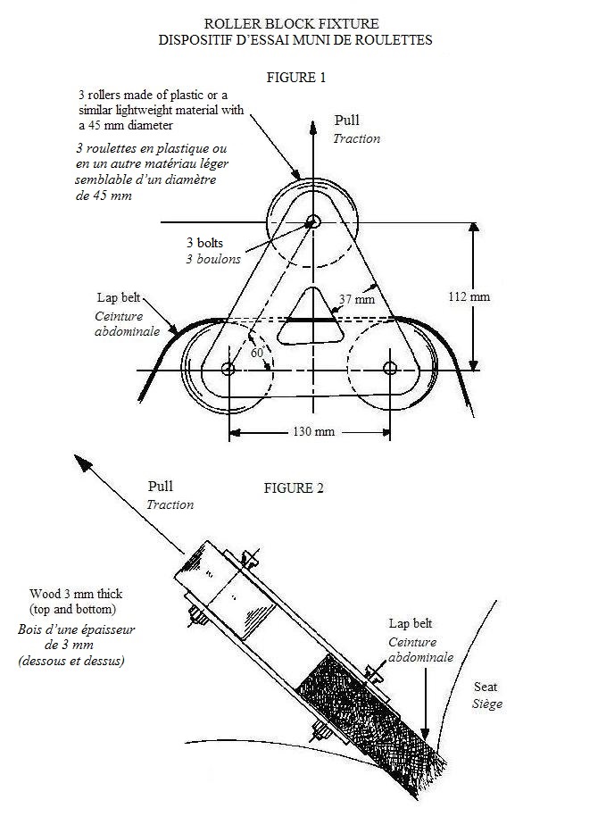
(b) secure the roller block fixture with the lap belt of the stroller as illustrated in Figure 1;
(c) mark the lap belt in any manner to allow observation of any loosening;
(d) apply a force of 200 N in the direction perpendicular to the belt as illustrated in Figure 2, in such a way as to allow the rollers to rotate freely, applying the force within a period of one second and maintaining it for 10 seconds;
(e) note any loosening or breakage of the fastener of the lap belt;
(f) repeat the steps set out in paragraphs (d) and (e) nine times at one-second intervals;
(g) repeat the step set out in paragraph (d) using a force of 450 N applied within two seconds;
(h) note any breakage or detachment of the anchorages;
(i) apply a force of 225 N to the restraint system, using any method, in a direction that places strain on one of the anchorage attachment points, applying the force within a period of two seconds and maintaining it for 10 seconds;
(j) note any breakage or detachment of the anchorage; and
(k) repeat the steps set out in paragraphs (i) and (j) for each of the remaining anchorage attachment points.
SCHEDULE 5(Paragraphs 7(1)(a) and (2)(a) and section 13)Latching System Testing
1 The following method is to be used for testing the latching system of a carriage or stroller that folds:
(a) erect the carriage or stroller in the manufacturer’s recommended use position;
(b) place a 2 kg bag of sand in the centre of each seating unit;
(c) secure the carriage or stroller to a horizontal surface in a manner that does not impede the normal folding action;
(d) apply a force of 200 N
(i) at the location normally associated with the folding action but not directly to the latching device itself, and
(ii) in the direction normally associated with the manufacturer’s recommended method of folding;
(e) note whether the carriage or stroller is still latched in the manufacturer’s recommended use position;
(f) repeat the steps set out in paragraphs (d) and (e) four times within two minutes; and
(g) fold the carriage or stroller 100 times and then repeat the steps set out in paragraphs (a) to (e).
2 The following method is to be used for testing the safety device of a carriage or stroller that folds:
(a) erect the carriage or stroller in the manufacturer’s recommended use position with the latching device released;
(b) apply a force of 200 N at the location and in the direction normally associated with the folding action of the carriage or stroller;
(c) note the amount of folding movement, if any; and
(d) repeat the steps set out in paragraphs (a) to (c) with a dummy that meets the requirements set out in Schedule 9, placed in the centre of each seating unit.
SCHEDULE 6(Sections 8 and 13)Structural Integrity Testing
1 The following method is to be used for testing the structural integrity of a carriage or stroller:
(a) erect the carriage or stroller in the manufacturer’s recommended use position with all wheels on a horizontal surface and each footrest in the lowest manufacturer’s recommended use position;
(b) place a test mass of 40 kg in each seating unit of the carriage and 60 kg in each seating unit of the stroller;
(c) maintain the test mass for two minutes;
(d) note any damage to the carriage or stroller;
(e) place a 70 mm × 150 mm × 25 mm wooden block on the centre of each footrest, if provided;
(f) place a test mass of 20 kg on each block for two minutes; and
(g) note any damage to the carriage or stroller.
SCHEDULE 7(Sections 9 and 13)Wheel Integrity Testing
1 The following method is to be used for testing the wheel attachment of a carriage or stroller:
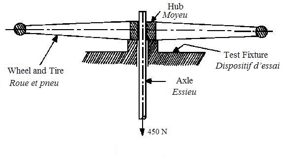
(a) mount a wheel and axle in a test fixture as illustrated in the figure;
(b) apply a force of 450 N to the axle, as illustrated in the figure, at a rate of loading not exceeding 450 N/min;
(c) maintain the force for a period of two minutes;
(d) reduce the load to zero at a rate not exceeding 450 N/min;
(e) note whether the wheel has become detached or suffered loss of function; and
(f) repeat the steps set out in paragraphs (a) to (e) for each of the other wheels of the carriage or stroller.
Figure
SCHEDULE 8(Section 11)Small Parts Cylinder

SCHEDULE 9(Schedules 1, 3 and 5)Dummy for Testing Purposes
1 A dummy that is to be used for testing purposes in accordance with these Regulations must be made from the following materials:
(a) sand having an approximate density of 1 600 kg/m3; and
(b) pre-shrunk 368.54 g marine canvas.
2 A dummy that is to be used for testing purposes in accordance with these Regulations must be made in the following manner:
(a) cut canvas to obtain a piece that is approximately 500 mm × 650 mm;
(b) fold it and stitch side and bottom seams to form a bag that is 475 mm × 300 mm;
(c) turn raw edges to the inside;
(d) fill it with dry sand to obtain a mass of 20 kg; and
(e) stitch the top edge closed to obtain a bag with finished dimensions of 450 mm × 300 mm.
Page Details
- Date modified: