
Table of Contents
Motor Vehicle Safety Regulations
C.R.C., c. 1038
Regulations Respecting Safety for Motor Vehicles and Motor Vehicle Components
Short Title
1 These Regulations may be cited as the Motor Vehicle Safety Regulations.
Interpretation
2 (1) In these Regulations,
- accessory mass
accessory mass means the total mass of the stock optional items with which a vehicle is capable of being equipped minus the total mass of the standard items that those optional items replace; (masse des accessoires)
- Act
Act means the Motor Vehicle Safety Act; (Loi)
- adjacent seat
adjacent seat means a designated seating position so located that a portion of its occupant space is not more than 25.4 cm from an emergency exit for a distance of at least 38.1 cm measured horizontally and parallel to the emergency exit; (siège adjacent)
- adjustment hardware
adjustment hardware means hardware designed for adjusting the size of a seat belt assembly to fit the user, including such hardware as may be integral with a buckle, a retractor or attachment hardware; (pièces de réglage)
- agricultural commodity trailer
agricultural commodity trailer[Repealed, SOR/99-357, s. 1]
- aiming reference plane
aiming reference plane[Repealed, SOR/96-366, s. 1]
- air bag
air bag means an inflatable automatic occupant protection system that may be deployed when a collision occurs; (sac gonflable)
- air brake system
air brake system means a brake system that uses air as a medium for transmitting pressure or force from the driver control to the service brake, including an air-over-hydraulic brake subsystem, but does not include a system that uses compressed air or vacuum only to assist the driver in applying muscular force to hydraulic or mechanical components; (système de freinage à air comprimé)
- all-terrain vehicle
all-terrain vehicle means a wheeled or tracked vehicle, other than a snowmobile or work vehicle, designed primarily for recreational use or for the transportation of property or equipment exclusively on undeveloped road rights of way, marshland, open country or other unprepared surfaces; (véhicule tout terrain)
- ambient temperature
ambient temperature means the surrounding air temperature measured at such a distance from a vehicle under test that the temperature is not significantly affected by heat from the vehicle; (température ambiante)
- American specifications vehicle
American specifications vehicle[Repealed, SOR/95-147, s. 1]
- ANS Z26
ANS Z26[Repealed, SOR/94-717, s. 1]
- ANSI Z26 Safety Code — 1990
ANSI Z26 Safety Code — 1990 means the American National Standard for Safety Glazing Materials for Glazing Motor Vehicles and Motor Vehicle Equipment Operating on Land Highways — Safety Code, Standard ANSI/SAE Z26.1 — 1990, published November 1990 and reprinted February 1992. (code de sécurité ANSI Z26 — 1990)
- ANSI Z26 Safety Standard — 1996
ANSI Z26 Safety Standard — 1996 means the American National Standard for Safety Glazing Materials for Glazing Motor Vehicles and Motor Vehicle Equipment Operating on Land Highways — Safety Standard, Standard ANSI/SAE Z26.1-1996, published on August 11,1997. (norme de sécurité ANSI Z26 — 1996)
- anthropomorphic test device
anthropomorphic test device means, except in section 202 of Schedule IV, a representation of a human being used in the measurement of the conditions that a human being would experience in a vehicle when the vehicle is subjected to approved test methods; (dispositif anthropomorphe d’essai)
- antilock brake system
antilock brake system or ABS means the portion of a service brake system that automatically controls the degree of rotational wheel slip during braking by
(a) sensing the rate of angular rotation of the wheels,
(b) transmitting signals regarding the rate of wheel angular rotation to one or more controlling devices that interpret those signals and generate responsive controlling output signals, and
(c) transmitting those controlling signals to one or more modulators that adjust brake actuating forces in response to those signals; (dispositif de frein anti-blocageouABS)
- antilock system
antilock system[Repealed, SOR/97-200, s. 1]
- antique reproduction vehicle
antique reproduction vehicle means a vehicle that is designed to be a scaled reproduction of an antique vehicle and
(a) may contain contemporary design components,
(b) has a motor that produces 8 kW (10.73 bhp) or less,
(c) is intended for use exclusively in parades, exhibitions and demonstrations, and
(d) bears a label, permanently affixed in a conspicuous position, stating that the vehicle is not to be used for public transportation, but is intended for use in parades, exhibitions and demonstrations; (réplique d’ancien modèle)
- antique vehicle
antique vehicle means a vehicle more than 30 years old that, when restored to a condition comparable to that on the date of its manufacture, retains the original components or incorporates replacement components with original design characteristics; (ancien modèle)
- approved
approved means approved by the Minister; (approuvé)
- armour
armour means, for the purposes of section 106, a protective material installed on a brake hose to increase the resistance of the hose or hose assembly to abrasion or impact damage; (armure)
- assembler
assembler[Repealed, SOR/95-147, s. 1]
- ASTM
ASTM means the American Society for Testing Materials; (ASTM)
- attachment hardware
attachment hardware means hardware designed for securing a seat belt assembly to the vehicle; (pièces de fixation)
- automatic-locking retractor
automatic-locking retractor means a retractor incorporating adjustment hardware that has a positive self-locking mechanism that is capable, when locked, of withstanding restraint forces; (rétracteur autobloquant)
- automatic occupant protection system
automatic occupant protection system means a protective restraining system for an occupant of a vehicle that does not require any deliberate action on the part of the occupant to be activated where that occupant enters, occupies or leaves the vehicle; (dispositif automatique de protection de l’occupant)
- auto transporter
auto transporter means a truck and a trailer designed for use in combination to transport motor vehicles where the truck is designed to carry cargo other than at the fifth wheel and that cargo is to be loaded only by means of the trailer; (porte-autos)
- backup system
backup system means a portion of a service brake system, such as a pump, that automatically supplies energy in the event of a primary brake power source failure; (système de secours)
- battery charging indicator
battery charging indicator means a device showing whether the battery is being charged or discharged; (indicateur de charge)
- battery charging tell-tale
battery charging tell-tale means a signal that, when alight, indicates that the battery is not being charged; (témoin de charge)
- beam contributor
beam contributor[Repealed, SOR/96-366, s. 1]
- blister
blister means, for the purposes of section 116 of Schedule IV, a cavity or sac on the surface of a brake cup; (ampoule)
- body type
body type means the general configuration or shape of a vehicle distinguished by the number of doors or windows, cargo carrying features, the roofline (e.g., sedan, fastback, hatchback) or other characteristics; (type de carrosserie)
- bonded construction sealed beam headlamp
bonded construction sealed beam headlamp[Repealed, SOR/96-366, s. 1]
- booster cushion
booster cushion[Repealed, SOR/98-160, s. 1]
- brake fluid
brake fluid means brake fluid for use in hydraulic brake systems, except hydraulic system mineral oil; (liquide pour freins)
- brake hose
brake hose means a flexible conduit, other than a vacuum tubing connector, manufactured for use in a brake system to transmit or contain the fluid pressure or vacuum used to apply force to a vehicle’s brakes; (boyau de frein)
- brake hose assembly
brake hose assembly means a brake hose, with or without armour, equipped with brake hose end fittings for use in a brake system, but does not include an air or vacuum assembly prepared by the owner or operator of a used vehicle, by his employee or by a repair facility, for installation in that used vehicle; (ensemble de boyau de frein)
- brake hose end fitting
brake hose end fitting means a coupler, other than a clamp, designed to be attached to the end of a brake hose; (raccord d’extrémité de boyau de frein)
- brake power assist unit
brake power assist unit means a device installed in a hydraulic brake system that reduces the amount of muscular force that a driver must apply to actuate the system, and that, if inoperative, does not prevent the driver from braking the vehicle by a continued application of muscular force on the service brake control; (unité d’assistance de frein)
- brake power unit
brake power unit means a device installed in a brake system that provides the energy required to actuate the brakes, either directly or indirectly, through an auxiliary device, with driver action consisting only of modulating the energy application level; (unité de servo-frein)
- braking interval
braking interval means the distance measured from the point of initiation of one brake application to the point of initiation of the next brake application; (intervalle de freinage)
- buckle
buckle means a quick-release connector that secures a person in a seat belt assembly; (attache)
- built-in booster cushion
built-in booster cushion means a device that is designed as an integral part of a vehicle seating system, for the purpose of seating a child in an elevated position on the vehicle seat in order to adapt an adult seat belt assembly of the motor vehicle to the child; (coussin d’appoint intégré)
- built-in child restraint system
built-in child restraint system means a device, except a Type 1 or Type 2 seat belt assembly, that is designed to restrain a child and that is an integral part of a vehicle seating system; (ensemble intégré de retenue d’enfant)
- built-in dual-purpose restraint system
built-in dual-purpose restraint system means a device that combines the function of a built-in child restraint system and a built-in booster cushion; (ensemble intégré de retenue à double usage)
- bus
bus means a vehicle having a designated seating capacity of more than 10, but does not include a trailer or a vehicle imported temporarily for special purposes; (autobus)
- bus trailer
bus trailer means a vehicle having a designated seating capacity of more than 10 and designed primarily to be drawn behind another vehicle; (remorque-autobus)
- C-dolly
C-dolly means a trailer converter dolly that is equipped with a single axle that is self-steering and with a coupling that is so designed that when the trailer converter dolly is coupled to a towing trailer, the trailer converter dolly cannot pivot horizontally with respect to the towing trailer; (chariot de conversion de type C)
- cable reel trailer
cable reel trailer means a vehicle designed to be drawn behind another vehicle for the exclusive purpose of carrying a drum or reel of cable; (chariot dérouleur)
- cargo-carrying capacity
cargo-carrying capacity means the mass that is equal to or less than the result obtained by subtracting from the gross vehicle weight rating the sum of
(a) the unloaded vehicle mass,
(b) the product obtained by multiplying the designated seating capacity by, in the case of a school bus, 55 kg or, in any other case, 70 kg, and
(c) in the case of a vehicle having living or sanitary accommodations, the mass of its fresh water, hot water and propane tanks, but not its waste water tanks, when full; (capacité de chargement)
- chassis-cab
chassis-cab[Repealed, SOR/2002-55, s. 1]
- check digit
check digit means a single number or the letter “X” used to verify the accuracy of the transcription of the vehicle identification number; (unité de contrôle)
- child
child means a person whose mass is between 9 kg (20 pounds) and 22 kg (48 pounds) inclusive; (enfant)
- child restraint system
child restraint system[Repealed, SOR/98-160, s. 1]
- chipping
chipping means, for the purposes of section 116 of Schedule IV, a condition in which small pieces are missing from the outer surface of a brake cup; (ébréché)
- CMVSS
CMVSS is an abbreviation for Canada Motor Vehicle Safety Standard; (NSVAC)
- competition car
competition car[Repealed, SOR/2000-182, s. 1]
- competition motorcycle
competition motorcycle[Repealed, SOR/2000-182, s. 1]
- competition snowmobile
competition snowmobile[Repealed, SOR/2000-182, s. 1]
- competition vehicle
competition vehicle means a vehicle that is designed for use exclusively in closed-course competition and
(a) bears a label affixed by the manufacturer stating, in both official languages, that the vehicle is a competition vehicle and is for use exclusively in closed-course competition, or
(b) is accompanied by a signed declaration clearly indicating that the vehicle is a competition vehicle and is for use exclusively in closed-course competition; (véhicule de compétition)
- completed vehicle
completed vehicle means a vehicle that needs no further manufacturing operations to perform its intended function, other than the addition of readily attachable components, such as mirrors or tire and rim assemblies, or minor finishing operations such as painting; (véhicule complet)
- compliance label
compliance label means the label required to be applied to a completed vehicle under section 6 or 6.6; (étiquette de conformité)
- compressed natural gas
compressed natural gas or CNG means natural gas, composed predominantly of methane, compressed at pressures up to 20 680 kPa (3,000 psi); (gaz naturel compriméorGNC)
- contactable surface
contactable surface[Repealed, SOR/98-160, s. 1]
- control
control means the part of a device that enables the driver to bring about a change in the state or functioning of a vehicle or vehicle component; (commande)
- convertible
convertible means a vehicle that has an A-pillar or windshield peripheral support, the upper portion of which is not joined by a fixed rigid structure to the B-pillar or other rear roof support to the rear of the B-pillar; (décapotable)
- CSA
CSA means the Canadian Standards Association; (CSA)
- curb mass
curb mass means the mass of a vehicle with standard equipment and carrying its maximum capacity of fuel, oil and coolant and includes the mass of any air-conditioning equipment on the vehicle and the amount by which the mass of any optional engine with which the vehicle is equipped exceeds the mass of the standard engine; (masse à vide)
- curb weight
curb weight means the weight of a vehicle with standard equipment and carrying its maximum capacity of fuel, oil and coolant and includes the weight of any air-conditioning equipment on the vehicle and the amount by which the weight of any optional engine with which the vehicle is equipped exceeds the weight of the standard engine; (poids à vide)
- custom restraint system for disabled persons
custom restraint system for disabled persons[Repealed, SOR/98-160, s. 1]
- cutaway chassis
cutaway chassis means an incomplete vehicle that has the back of the cab cut out for the intended installation of a structure that permits access from the driver’s area to the back of the vehicle; (châssis tronqué)
- daytime running lamp
daytime running lamp means, for the purposes of section 108 of Schedule IV, a lamp used to improve the visibility of a vehicle when the vehicle is viewed from the front in daylight; (feu de jour)
- demountable rim
demountable rim means a supporting member for a tire or tire and tube assembly, that does not have a permanently attached centre component; (jante amovible)
- designated seating capacity
designated seating capacity means the number of designated seating positions provided in a vehicle or, in the case of a motor home that has a GVWR greater than 4 536 kg, may, at the option of the manufacturer, mean the number of sleeping positions provided in the motor home; (nombre désigné de places assises)
- designated seating position
designated seating position means any plan view position capable of accommodating a person at least as large as a 5th percentile adult female, as defined in section 100 of Schedule IV, where the overall seat configuration and design and the vehicle design are such that the position is likely to be used as a seating position while the vehicle is in motion, but does not include any plan view position of temporary or folding jump seats or other auxiliary seating accommodation; (place assise désignée)
- disc wheel
disc wheel means a supporting member for a tire or tire and tube assembly, comprising a rim with a dish-shaped component that is permanently attached to the inner circumference of the rim; (roue à disque)
- display
display means an indicator, a tell-tale or an alphanumeric readout, or a collection of indicators, tell-tales and alphanumeric readouts, on the instrument panel of a vehicle; (affichage)
- distributor
distributor[Repealed, SOR/95-147, s. 1]
- driver
driver means the occupant of a vehicle seated immediately behind the steering control system; (conducteur)
- driver-operated accelerator control system
driver-operated accelerator control system means all components of a vehicle, except the fuel metering device, that regulate engine speed in direct response to movement of the driver-operated control and that return the throttle to the idle position upon release of the driver-operated control; (système de commande d’accélération actionné par le conducteur)
- ECE
ECE means the United Nations Economic Commission for Europe, Inland Transport Committee; (CEE)
- effective projected luminous lens area
effective projected luminous lens area[Repealed, SOR/96-366, s. 1]
- emergency brake
emergency brake means a mechanism designed to stop a vehicle after a failure of the service brake system; (frein de secours)
- emergency-locking retractor
emergency-locking retractor means a retractor incorporating adjustment hardware that has a locking mechanism that is activated by vehicle acceleration, webbing movement in relation to the vehicle or other automatic action during an emergency, and is capable, when locked, of withstanding restraint forces; (rétracteur à blocage d’urgence)
- emergency vehicle
emergency vehicle means any fire-fighting vehicle, ambulance, police vehicle or other vehicle that is used for the purpose of an emergency; (véhicule de secours)
- enclosed motorcycle
enclosed motorcycle means a motorcycle that
(a) has steering handlebars that are completely constrained from rotating in relation to the axle of only one wheel in contact with the ground,
(b) is designed to travel on two wheels in contact with the ground,
(c) has a minimum seat height, when the vehicle is unladen, of 650 mm, and
(d) has a structure partially or fully enclosing the driver and passenger that is an integral part of the vehicle chassis; (motocyclette à habitacle fermé)
- engine coolant temperature indicator
engine coolant temperature indicator means a device that presents information concerning the temperature of the coolant; (indicateur de température du liquide de refroidissement)
- engine coolant temperature tell-tale
engine coolant temperature tell-tale means a signal that, when alight, indicates that the temperature of the engine coolant is above the normal engine running temperature prescribed by the manufacturer; (témoin de température du liquide de refroidissement)
- engine type
engine type means a power source distinguished by the fuel utilized, number of cylinders, displacement, net brake horsepower or other characteristics; (type de moteur)
- ERBP
ERBP means, for the purposes of section 116 of Schedule IV, equilibrium reflux boiling point; (ERBP)
- final-stage manufacturer
final-stage manufacturer means a company that performs the manufacturing operations on an incomplete vehicle that turn the incomplete vehicle into a completed vehicle; (fabricant à l’étape finale)
- flash
flash means a cycle of automatic activation and deactivation of a lamp that continues until stopped either automatically or manually; (clignotement)
- forward control configuration
forward control configuration means a configuration in which more than half of the engine length is rearward of the foremost point of the windshield base and the steering wheel hub is in the forward quarter of the vehicle length; (type à cabine avancée)
- free length
free length means, for the purposes of section 106, the linear measurement of brake hose in a straight position exposed between the brake hose end fittings of a brake hose assembly; (longueur libre)
- fuel container
fuel container means one or more fuel containers with integral valving, pressure relief devices, tubing, hoses and mounting brackets; (réservoir de carburant)
- fuel level indicator
fuel level indicator means a device that presents information concerning the amount of fuel in the tank; (indicateur de niveau de carburant)
- fuel level tell-tale
fuel level tell-tale means a signal that, when alight, indicates that the fuel level is close to zero or that the vehicle is running on its fuel reserve; (témoin de niveau de carburant)
- fuel metering device
fuel metering device means the carburetor, fuel injector, fuel distributor or fuel injection pump; (dispositif de dosage du carburant)
- fuel spillage
fuel spillage means the fall, flow or run of fuel from a vehicle but does not include wetness resulting from capillary action; (écoulement de carburant)
- fuel system
fuel system means all components used to store fuel or supply fuel to a vehicle engine; (circuit d’alimentation en carburant)
- full trailer
full trailer, for the purposes of Technical Standards Document No. 121, Air Brake Systems, means a trailer, except a pole trailer, that is equipped with two or more axles that support the entire weight of the trailer and its load; (remorque complète)
- gasoline
gasoline[Repealed, SOR/2002-187, s. 1]
- glazing material manufacturer
glazing material manufacturer means a person engaged in the business of fabricating, laminating or tempering glazing material. (fabricant de vitrages)
- grade
grade means, for the purposes of section 116 of Schedule IV, a classification of brake fluid on the basis of its physical and chemical properties; (catégorie)
- gross axle weight rating
gross axle weight rating or GAWR means the value specified by the vehicle manufacturer as the load-carrying capacity of a single axle system, as measured at the tire-ground interfaces; (poids nominal brut sur l’essieuorPNBE)
- gross vehicle weight rating
gross vehicle weight rating or GVWR means the value specified by the vehicle manufacturer as the loaded weight of a single vehicle; (poids nominal brut du véhiculeorPNBV)
- H-point
H-point means the mechanically hinged hip point of a manikin that simulates the actual pivot centre of the human torso and thigh, described in SAE Standard J826 APR80, Devices for Use in Defining and Measuring Vehicle Seating Accommodation; (point H)
- H-V axis
H-V axis means the characteristic axis of the light pattern of a lamp, passing through the centre of the light source, used as the direction of reference (H = 0°, V = 0°) for photometric measurements and for the design of the installation of a lamp on a vehicle; (axe H-V)
- hardware
hardware means any metal or rigid plastic part designed to secure a person in a vehicle in conjunction with straps or webbing; (pièces)
- headlamp
headlamp means, for the purposes of sections 108 and 108.1 of Schedule IV, a lamp used to illuminate the road and objects on the road ahead of the vehicle, but does not include a fog lamp or a supplementary driving lamp; (projecteur)
- headlamp assembly
headlamp assembly means an assembly that consists of one or more headlamps, aiming devices, headlamp retaining components, electrical connectors and mounting brackets, and which may include a housing and one or more bulbs; (montage de projecteur)
- heavy duty vehicle
heavy duty vehicle[Repealed, SOR/2001-35, s. 1]
- heavy hauler trailer
heavy hauler trailer means a trailer that has
(a) brake lines designed to adapt to separation or extension of the vehicle frame, or
(b) a body that consists of only a platform the primary cargo-carrying surface of which is not more than 101.6 cm (40 inches) above the ground in an unloaded condition, but may include sides that are designed for easy removal and a permanent front end structure; (remorque lourde)
- high-pressure portion of the fuel system
high-pressure portion of the fuel system means, for a vehicle that uses LPG or CNG as a source of energy for its propulsion, all the components of the fuel system from and including the fuel container to, but not including, the first stage regulator; (partie haute pression du circuit d’alimentation en carburant)
- hub
hub means a rotating member that provides for mounting of disc wheels; (moyeu)
- hydraulic brake system
hydraulic brake system means a system that uses hydraulic fluid as a medium for transmitting force from a service brake control to the service brake, and that may incorporate a brake power assist unit or a brake power unit; (système de freinage hydraulique)
- hydraulic system mineral oil
hydraulic system mineral oil means a mineral-oil-based fluid designed for use in motor vehicle brake systems in which none of the components contacting the fluid are SBR, EPDM, neoprene or natural rubber; (huile minérale pour système hydraulique)
- idle position
idle position means the position of the throttle at which it first comes in contact with an engine idle speed control appropriate for existing conditions according to the manufacturers’ recommendations respecting engine speed adjustments for a cold engine, air conditioning, emission control and throttle setting devices; (position de ralenti)
- imported used vehicle
imported used vehicle[Repealed, SOR/92-173, s. 1]
- importer
importer[Repealed, SOR/95-147, s. 1]
- incomplete trailer
incomplete trailer means a vehicle, other than a vehicle imported temporarily for special purposes, that is capable of being drawn and that consists, at a minimum, of a chassis structure and suspension system but needs further manufacturing operations performed on it to become a completed vehicle; (remorque incomplète)
- incomplete vehicle
incomplete vehicle means a vehicle
(a) other than a vehicle imported temporarily for special purposes, that is capable of being driven and that consists, at a minimum, of a chassis structure, power train, steering system, suspension system and braking system in the state in which those systems are to be part of the completed vehicle, but requires further manufacturing operations to become a completed vehicle, or
(b) that is an incomplete trailer; (véhicule incomplet)
- incomplete vehicle manufacturer
incomplete vehicle manufacturer means a company that manufactures an incomplete vehicle by assembling components none of which, taken separately, constitutes an incomplete vehicle; (fabricant de véhicules incomplets)
- indicator
indicator means the part of an instrument that shows the quantity of the physical characteristic that the instrument is designed to sense; (indicateur)
- infant
infant means a person whose mass is less than 9 kg; (bébé)
- infant restraint system
infant restraint system[Repealed, SOR/98-160, s. 1]
- information label
information label means the label required to be applied to an incomplete vehicle under section 6.2 or 6.4; (étiquette informative)
- information readout display
information readout display[Repealed, SOR/93-31, s. 1]
- initial brake temperature
initial brake temperature[Repealed, SOR/99-357, s. 1]
- inspector
inspector[Repealed, SOR/95-147, s. 1]
- integral headlamp aiming device
integral headlamp aiming device[Repealed, SOR/96-366, s. 1]
- intermediate manufacturer
intermediate manufacturer means a company, other than an incomplete vehicle manufacturer or final-stage manufacturer, that performs manufacturing operations on an incomplete vehicle; (fabricant intermédiaire)
- IRHD
IRHD means International Rubber Hardness Degrees as referred to in ASTM D1415-1968, Standard Test Method of International Hardness of Vulcanized Natural and Synthetic Rubbers; (IRHD)
- leaded gasoline
leaded gasoline means gasoline that contains more than
(a) 0.06 grams of lead per Imperial gallon (0.013 grams per litre), or
(b) 0.006 grams of phosphorous per Imperial gallon (0.0013 grams per litre); (essence au plomb)
- light duty vehicle
light duty vehicle[Repealed, SOR/2001-35, s. 1]
- light source
light source[Repealed, SOR/96-366, s. 1]
- lightly loaded vehicle weight
lightly loaded vehicle weight[Repealed, SOR/99-357, s. 1]
- limited-speed motorcycle
limited-speed motorcycle means a motorcycle that
(a) has steering handlebars that are completely constrained from rotating in relation to the axle of only one wheel in contact with the ground,
(b) has a maximum attainable speed of 70 km/h or less, measured in accordance with International Organization for Standardization standard ISO 7117-1981, Road vehicles — measurement method for the maximum speed of motorcycles,
(c) has a minimum seat height, when the vehicle is unladen, of 650 mm, and
(d) does not have a structure partially or fully enclosing the driver and passenger, other than that part of the vehicle forward of the driver’s torso and the seat backrest; (motocyclette à vitesse limitée)
- line
line means the name that a manufacturer applies to a family of vehicles within a make that have a degree of commonality of body, chassis, cab type or other features of construction; (ligne)
- liquefied petroleum gas
liquefied petroleum gas or LPG means a hydrocarbon product that meets National Standard of Canada CAN/CGSB-3.14-M88, Liquefied Petroleum Gas (Propane) (August 1988). (gaz de pétrole liquéfiéouGPL)
- load divider dolly
load divider dolly means a trailer that consists of a trailer chassis and one or more axles, with no solid bed, body or container attached, and that is designed exclusively to support a portion of the load on a trailer or truck excluded from all the requirements of Technical Standards Document No. 121, Air Brake Systems; (chariot de répartition de charge)
- load limiter
load limiter means a seat belt assembly component or seat belt assembly feature that controls tension on a seat belt to modulate the forces that are imparted to an occupant restrained by the seat belt assembly during a collision; (limiteur de charge)
- lower connector system
lower connector system means a system consisting of two connectors that each fit inside a checking device that has the envelope dimensions shown in Figure 10 of Schedule 10 to the Motor Vehicle Restraint Systems and Booster Cushions Safety Regulations, are attached to the lower part of a restraint system or booster cushion in a manner that does not allow for their removal without the use of tools, and enable the restraint system or booster cushion to be securely attached to a lower universal anchorage system of a vehicle; (système d’attaches inférieures)
- lower universal anchorage system
lower universal anchorage system means a device, other than a vehicle seat belt, that is designed to secure the lower part of a restraint system or booster cushion to a vehicle and that transfers loads from the restraint system or booster cushion and its occupant to the vehicle structure or seat; (dispositif universel d’ancrages d’attaches inférieurs)
- low-speed vehicle
low-speed vehicle means a vehicle, other than an all-terrain vehicle, a truck or a vehicle imported temporarily for special purposes, that
(a) is powered by an electric motor,
(b) produces no emissions,
(c) is designed to travel on four wheels and has an attainable speed in 1.6 km of more than 32 km/h but not more than 40 km/h on a paved level surface; (véhicule à basse vitesse)
- make
make means the name that a manufacturer applies to a group of vehicles; (marque)
- manual seat belt assembly
manual seat belt assembly means, with respect to a Type 1 or Type 2 seat belt assembly, an assembly that requires a deliberate action on the part of the occupant of a vehicle to be activated; (ceinture de sécurité manuelle)
- manufacturer
manufacturer[Repealed, SOR/95-147, s. 1]
- master lighting switch
master lighting switch means a switch with one or more operational positions that controls the tail lamps, parking lamp, licence plate lamp, side marker lamps and headlamps and may control identification lamps and clearance lamps; (commutateur général d’éclairage)
- maximum load
maximum load means, for the purpose of section 110 of Schedule IV, the portion of the mass of a vehicle that
(a) is borne by each tire when
(i) the tire is installed on the vehicle, and
(ii) the vehicle is at its maximum loaded vehicle mass and is resting on a horizontal plane, and
(b) is calculated by distributing to each axle its share of the maximum loaded vehicle mass and dividing that share by two; (charge maximale)
- maximum loaded vehicle mass
maximum loaded vehicle mass means, for the purpose of section 110 of Schedule IV, the sum of
(a) the curb mass,
(b) the accessory mass,
(c) the vehicle capacity mass, and
(d) the production options mass; (masse maximale de véhicule chargé)
- minibike
minibike[Repealed, SOR/88-268, s. 1]
- Minister
Minister means the Minister of Transport; (ministre)
- mobile home
mobile home means a vehicle that is more than 102 inches in overall width and that is designed to be drawn behind another vehicle and to be used as a living or working accommodation unit; (maison roulante)
- mobility-impaired occupant
mobility-impaired occupant means a person whose mass is 9 kg or more and who, for orthopaedic reasons or because of the person’s size, build or other physical characteristics, is unable to use a child restraint system or a Type 1 or Type 2 seat belt; (occupant à mobilité réduite)
- model
model means the name that a manufacturer applies to a family of vehicles of the same class, make, line, series and body type; (modèle)
- model year
model year means the year used to designate a discrete vehicle model irrespective of the calendar year in which the vehicle was actually produced, so long as the period of such production is less than two years; (année de modèle)
- moped
moped[Repealed, SOR/88-268, s. 1]
- motorcycle
motorcycle means a vehicle of the subclasses enclosed motorcycle, open motorcycle, limited-speed motorcycle and motor tricycle, that
(a) is designed to travel on not more than three wheels in contact with the ground,
(b) has a minimum wheel rim diameter of 250 mm, and
(c) has a minimum wheelbase of 1 016 mm,
but does not include a power-assisted bicycle, a restricted-use motorcycle, a low-speed vehicle, a passenger car, a truck, a multi-purpose passenger vehicle, a competition vehicle, a vehicle imported temporarily for special purposes or a three-wheeled vehicle; (motocyclette)
- motor driven cycle
motor driven cycle[Repealed, SOR/88-268, s. 1]
- motor home
motor home means a multi-purpose passenger vehicle that is designed to provide temporary residential accommodations, as evidenced by the presence of at least four of the following:
(a) cooking facilities,
(b) a refrigerator or ice box,
(c) a self-contained toilet,
(d) a heating or air-conditioning system that can function independently of the vehicle engine,
(e) a potable water supply system that includes a faucet and sink, and
(f) a separate 110- to 125-V electric power supply or an LP gas supply; (autocaravane)
- motor tricycle
motor tricycle means a motorcycle, other than an antique reproduction vehicle, that
(a) is designed to travel on three wheels in contact with the ground,
(b) has seating on which all occupants must sit astride,
(c) has no more than four designated seating positions,
(d) has a GVWR of 1 000 kg or less; and
(e) does not have a structure partially or fully enclosing the driver and passenger, other than that part of the vehicle forward of the driver’s torso and the seat backrest; (tricycle à moteur)
- Motor Vehicle Safety Test Methods
Motor Vehicle Safety Test Methods[Repealed, SOR/97-141, s. 1]
- Motor Vehicle Safety Test Methods, section 106, “Brake Hoses”
Motor Vehicle Safety Test Methods, section 106, “Brake Hoses” means the document entitled Motor Vehicle Safety Test Methods, section 106 — Brake Hoses (November 1, 1996); (Méthodes d’essai de sécurité des véhicules automobiles, article 106, « Boyaux de frein »)
- Motor Vehicle Safety Test Methods, section 116, “Hydraulic Brake Fluid”
Motor Vehicle Safety Test Methods, section 116, “Hydraulic Brake Fluid”[Repealed, SOR/95-536, s. 7]
- Motor Vehicle Safety Test Methods, section 116, “Hydraulic Brake Fluids”
Motor Vehicle Safety Test Methods, section 116, “Hydraulic Brake Fluids” means the document entitled Motor Vehicle Test Methods, section 116 — Hydraulic Brake Fluids (November 1, 1996); (Méthodes d’essai de sécurité des véhicules automobiles, article 116, « Liquides pour freins hydrauliques »)
- multiple compartment lamp
multiple compartment lamp[Repealed, SOR/96-366, s. 1]
- multiple lamp arrangement
multiple lamp arrangement[Repealed, SOR/96-366, s. 1]
- multi-purpose passenger vehicle
multi-purpose passenger vehicle means a vehicle having a designated seating capacity of 10 or less that is constructed either on a truck chassis or with special features for occasional off-road operation, but does not include an air cushion vehicle, an all-terrain vehicle, a golf cart, a low-speed vehicle, a passenger car, a three-wheeled vehicle, a truck or a vehicle imported temporarily for special purposes; (véhicule de tourisme à usages multiples)
- non-locking retractor
non-locking retractor means a retractor that does not have a locking mechanism, from which the webbing can be extended to substantially its full length by a small external force, that provides no adjustment for assembly length and that need not be capable of sustaining restraint forces at maximum webbing extension; (rétracteur sans blocage)
- normal load
normal load of a tire means, for the purpose of section 110 of Schedule IV, the portion of the mass of a vehicle that
(a) is borne by each tire when
(i) the tire is installed on the vehicle,
(ii) the vehicle is at a mass equal to the sum of the curb mass, the accessory mass and the normal occupants’ mass and the vehicle is resting on a horizontal plane, and
(iii) the normal occupants’ mass is distributed in the vehicle in accordance with Table I to section 110 of Schedule IV, and
(b) is calculated by
(i) distributing to each axle its share of the aggregate of the masses referred to in subparagraph (a)(ii), and
(ii) dividing that share by two; (charge normale)
- normal occupants’ mass
normal occupants’ mass means 70 kg multiplied by the number of occupants set out in column II of the table to section 110 of Schedule IV; (masse normale des occupants)
- occupant
occupant means a person or manikin seated in a vehicle and unless otherwise specified means a person or manikin having the dimensions and weight of a 95th percentile adult male, as defined in section 100 of Schedule IV; (occupant)
- occupant compartment air space
occupant compartment air space means the space within an occupant compartment that normally contains refreshable air; (espace d’air de l’habitacle)
- occupant distribution
occupant distribution means the distribution of occupants in a vehicle in a manner specified in Column III of Table I to section 110 of Schedule IV; (répartition des occupants)
- occupant space
occupant space means the space directly above the seat and footwell, bounded vertically by the ceiling and horizontally by the normally positioned seat back and the nearest obstruction of occupant motion in the direction the seat faces; (espace d’occupant)
- off-road motorcycle
off-road motorcycle[Repealed, SOR/88-268, s. 1]
- oil pressure indicator
oil pressure indicator means a device that presents information concerning the pressure of the oil in the engine lubrication circuit; (indicateur de pression d’huile)
- oil pressure tell-tale
oil pressure tell-tale means a signal that, when alight, indicates that the oil pressure in the engine lubrication circuit is below the normal operating limit prescribed by the manufacturer; (témoin de pression d’huile)
- on-highway vehicle
on-highway vehicle[Repealed, SOR/2004-250, s. 1]
- on-off-highway vehicle
on-off-highway vehicle[Repealed, SOR/2004-250, s. 1]
- open-body type vehicle
open-body type vehicle means a convertible vehicle that has no top over the occupants’ compartment or that has over the occupants’ compartment a top that can easily be installed or removed by the operator of the vehicle; (véhicule de type ouvert)
- open motorcycle
open motorcycle means a motorcycle that
(a) has steering handlebars that are completely constrained from rotating in relation to the axle of only one wheel in contact with the ground,
(b) is designed to travel on two wheels in contact with the ground,
(c) has a minimum seat height, when the vehicle is unladen, of 650 mm, and
(d) does not have a structure partially or fully enclosing the driver and passenger, other than that part of the vehicle forward of the driver’s torso and the seat backrest; (motocyclette sans habitacle fermé)
- optically combined lamps
optically combined lamps means, for the purposes of section 108 of Schedule IV, lamps that have
(a) two or more separate light sources or a single light source that operates in different ways,
(b) one lens totally or partly in common, and
(c) a common lamp body; (feux combinés optiquement)
- optional item
optional item means automatic transmission, power steering, power brakes, power windows, power seats, a radio or heater; (articles facultatifs)
- overall width
overall width means the nominal design dimension of the widest part of the vehicle with doors and windows closed and wheels in the straight ahead position, exclusive of signal lamps, marker lamps, outside rearview mirrors, flexible fender extensions and mud flaps; (largeur hors tout)
- parking brake
parking brake means a mechanism designed to prevent the movement of a stationary vehicle; (frein de stationnement)
- parking mechanism
parking mechanism[Repealed, SOR/99-357, s. 1]
- passenger car
passenger car means a vehicle having a designated seating capacity of 10 or less, but does not include an all-terrain vehicle, a competition vehicle, a low-speed vehicle, a multi-purpose passenger vehicle, an antique reproduction vehicle, a motorcycle, a truck, a trailer, a vehicle imported temporarily for special purposes or a three-wheeled vehicle; (voiture de tourisme)
- passive occupant protection
passive occupant protection[Repealed, SOR/93-5, s. 1]
- passive restraint system
passive restraint system[Repealed, SOR/93-5, s. 1]
- pelvic restraint
pelvic restraint means a seat belt assembly or portion thereof intended to restrain movement of the pelvis; (ceinture sous-abdominale)
- permanently attached hose end fitting
permanently attached hose end fitting means a brake hose end fitting that is
(a) permanently attached to a brake hose by deformation of the fitting about the hose by crimping or swaging, or
(b) attached to a brake hose by use of a sacrificial sleeve or ferrule that requires replacement each time a brake hose assembly is rebuilt; (raccord d’extrémité de boyau fixé en permanence)
- plant of manufacture
plant of manufacture means the plant at which the manufacturer affixes the vehicle identification number; (usine de construction)
- pole trailer
pole trailer means a vehicle designed to be drawn behind another vehicle by means of a reach or pole, or by being boomed or otherwise secured to the towing vehicle, for the purpose of transporting poles, pipes, structural members or other long or irregularly shaped loads capable generally of sustaining themselves as beams between the supporting connections; (remorque pour charges longues)
- power-assisted bicycle
power-assisted bicycle means a vehicle that:
(a) has steering handlebars and is equipped with pedals,
(b) is designed to travel on not more than three wheels in contact with the ground,
(c) is capable of being propelled by muscular power,
(d) has one or more electric motors that have, singly or in combination, the following characteristics:
(i) it has a total continuous power output rating, measured at the shaft of each motor, of 500 W or less,
(ii) if it is engaged by the use of muscular power, power assistance immediately ceases when the muscular power ceases,
(iii) if it is engaged by the use of an accelerator controller, power assistance immediately ceases when the brakes are applied, and
(iv) it is incapable of providing further assistance when the bicycle attains a speed of 32 km/h on level ground,
(e) bears a label that is permanently affixed by the manufacturer and appears in a conspicuous location stating, in both official languages, that the vehicle is a power-assisted bicycle as defined in this subsection, and
(f) has one of the following safety features,
(i) an enabling mechanism to turn the electric motor on and off that is separate from the accelerator controller and fitted in such a manner that it is operable by the driver, or
(ii) a mechanism that prevents the motor from being engaged before the bicycle attains a speed of 3 km/h; (bicyclette assistée)
- power-operated roof panel
power-operated roof panel means a panel, in the roof of a vehicle, that moves on slides or hinges, the opening or closing of which is operated by a power source within the vehicle; (panneau du pavillon à servocommande)
- prescribed class
prescribed class means a class of vehicle listed in Schedule III or the class of incomplete vehicle prescribed under subsection 4(1.1); (catégorie réglementaire)
- prime glazing material manufacturer
prime glazing material manufacturer[Repealed, SOR/2002-187, s. 1]
- production options mass
production options mass means the combined mass of all installed regular optional items with a mass of over 2.3 kg (5 pounds) in excess of the standard items that those optional items replace and that is not included in the curb mass or accessory mass, including heavy duty brakes, ride levellers, roof rack, heavy duty battery and special trim; (masse des articles facultatifs de production courante)
- production restraint system for disabled persons
production restraint system for disabled persons[Repealed, SOR/98-160, s. 1]
- pulpwood trailer
pulpwood trailer[Repealed, SOR/99-357, s. 1]
- push-out window
push-out window means a vehicle window designed to open outward to provide for emergency egress; (fenêtre basculante)
- readily removable window
readily removable window means a window that can be quickly and completely removed from a vehicle without tools and, in the case of a bus having a GVWR of more than 4 535.9 kg (10,000 pounds), shall include a push-out window and a window mounted in an emergency exit that can be manually pushed out of its location in the vehicle without the use of tools, regardless of whether the window remains hinged at one side to the vehicle; (fenêtre amovible)
- recreational trailer
recreational trailer means a trailer designed to provide temporary living accommodation for travel, vacation or recreational use; (remorque de camping)
- replaceable bulb headlamp
replaceable bulb headlamp[Repealed, SOR/96-366, s. 1]
- restraint system
restraint system means a removable device designed to be installed in a vehicle for use in the restraint of an infant, a child or a mobility-impaired occupant but does not include booster cushions or vehicle seat belts; (ensemble de retenue)
- restraint system for disabled persons
restraint system for disabled persons[Repealed, SOR/98-160, s. 1]
- restricted-use motorcycle
restricted-use motorcycle means a vehicle, excluding a power-assisted bicycle, a competition vehicle and a vehicle imported temporarily for special purposes, but including an all-terrain vehicle designed primarily for recreational use, that:
(a) has steering handlebars,
(b) is designed to travel on not more than four wheels in contact with the ground,
(c) does not have as an integral part of the vehicle a structure to enclose the driver and passenger, other than that part of the vehicle forward of the driver’s torso and the seat backrest, and
(d) bears a label, permanently affixed in a conspicuous location, stating, in both official languages, that the vehicle is a restricted-use motorcycle or an all-terrain vehicle and is not intended for use on public highways; (motocyclette à usage restreint)
- retractor
retractor means a device for storing part or all of the webbing in a seat belt assembly; (rétracteur)
- rim base
rim base means that portion of a rim remaining after removal of all split or continuous rim flanges, side rings, and locking rings that can be detached from the rim; (base de jante)
- rim diameter
rim diameter means the nominal diameter of the bead seat; (diamètre de jante)
- rim size designation
rim size designation means the rim diameter and width; (désignation des dimensions de jante)
- rim type designation
rim type designation means the industry or manufacturer’s designation for a rim by style or code; (désignation du type de jante)
- rim width
rim width means the nominal distance between rim flanges; (largeur de jante)
- rupture
rupture means, for the purposes of section 106, any failure that results in the separation of a brake hose from its brake hose end fitting or in leakage; (rupture)
- SAE
SAE means the Society of Automotive Engineers, Inc.; (SAE)
- SAE Compatibility Fluid
SAE Compatibility Fluid means SAE RM-66-04 Compatibility Fluid as described in Appendix B of SAE Standard J1703, Motor Vehicle Brake Fluid, January 1995; (liquide de compatibilité SAE)
- school bus
school bus means a bus designed or equipped primarily to carry students to and from school; (autobus scolaire)
- scuffing
scuffing means, for the purposes of section 116 of Schedule IV, a visible erosion of a portion of the outer surface of a brake cup; (éraflure)
- sealed beam headlamp
sealed beam headlamp means, for the purposes of sections 108 and 108.1 of Schedule IV, a headlamp comprising a reflector, a lens and one or more light sources, forming an integral whole which is indivisibly formed and cannot be dismantled without rendering the unit completely unusable; (projecteur scellé)
- seat anchorage
seat anchorage means any component that transfers a vehicle seat load to the vehicle structure; (ancrage du siège)
- seat back retainer
seat back retainer means the portion of a seat belt assembly designed to restrict forward movement of the seat back; (dispositif de maintien du dossier)
- seat belt anchorage
seat belt anchorage means any component, other than the webbing or straps, involved in transferring seat belt load to the vehicle structure, including the attachment hardware, seat frames, seat pedestals, the vehicle structure and any part of the vehicle the failure of which causes separation of the belt from the vehicle structure; (ancrage de ceinture de sécurité)
- seat belt assembly
seat belt assembly means any strap, webbing or similar device designed to secure a person in a vehicle in order to mitigate the results of any accident and includes
(a) all necessary buckles and other fasteners and all hardware, and
(b) a belt assembly that is part of an automatic occupant protection system; (ceinture de sécurité)
- seat orientation reference line (SORL)
seat orientation reference line (SORL) means the horizontal line through point Z as illustrated in Figure 1 of sections 213, 213.1 and 213.3; (ligne repère d’orientation du siège (LROS))
- seating reference point
seating reference point means the unique Design H-point, as defined in section 2.2.11.1 of SAE Recommended Practice J1100 (June 1993), that
(a) establishes the rearmost normal design driving or riding position of each designated seating position, taking into account all modes of adjustment — horizontal, vertical and tilt — in a vehicle,
(b) has X, Y and Z coordinates, as defined in section 2.2.3 of SAE Recommended Practice J1100 (June 1993), established relative to the designed vehicle structure,
(c) simulates the position of the pivot centre of the human torso and thigh, and
(d) is the reference point employed to position the H-point template with the 95th percentile leg, as described in section 3.1 of SAE Standard J826 (June 1992), or, if that drafting template cannot be positioned, the reference point when the seat is in its rearmost adjustment position; (point de référence de position assise)
- series
series means the name that a manufacturer applies to a subdivision of a line denoting the price, size or weight identification and that is utilized by the manufacturer for marketing purposes; (série)
- service brake
service brake means the primary mechanism designed to stop a vehicle; (frein de service)
- sloughing
sloughing means, for the purposes of section 116 of Schedule IV, such degradation of a brake cup, evidenced by the presence of carbon black loosely held on the brake cup surface, that a visible black streak is produced when the cup, with 500 ± 10 gram deadweight applied to it, is drawn base down over a sheet of white bond paper placed on a firm flat surface; (encrassement)
- snowmobile
snowmobile means a vehicle, excluding a competition vehicle and a vehicle imported temporarily for special purposes, but including a snowmobile conversion vehicle, that has a mass of not more than 450 kg, is designed primarily for travel on snow, has one or more steering skis and is driven by means of an endless belt or belts in contact with the ground; (motoneige)
- snowmobile conversion vehicle
snowmobile conversion vehicle means a vehicle designed to be capable of conversion to a snowmobile by the repositioning or addition of parts; (véhicule convertible en motoneige)
- snowmobile cutter
snowmobile cutter means a sleigh designed to be drawn behind a snowmobile; (traîneau de motoneige)
- snowmobile trailer
snowmobile trailer means a trailer designed primarily for the transportation of snowmobiles or snowmobile cutters; (remorque pour motoneige)
- snub
snub means the braking deceleration of a vehicle from a higher reference speed to a lower reference speed that is greater than zero; (ralentissement)
- special driver accommodation
special driver accommodation includes a driver’s seat that is designed to be removable or that has extended adjustment capability to allow a person to transfer from a wheelchair to the driver’s seat; (place du conducteur particulière)
- speed attainable in 1.6 km (1 mile)
speed attainable in 1.6 km (1 mile) means the speed attainable by accelerating at maximum rate from a standing start for 1.6 km on a level surface; (vitesse à 1,6 km (1 mille))
- speed attainable in 3.2 km (2 miles)
speed attainable in 3.2 km (2 miles) means the speed attainable by accelerating at maximum rate from a standing start for 3.2 km on a level surface; (vitesse à 3,2 km (2 milles))
- spike stop
spike stop means a stop resulting from the application of 889.6 N (200 pounds) of force on the service brake control in 0.08 second; (arrêt d’urgence)
- split service brake system
split service brake system means a brake system consisting of two or more subsystems actuated by a single control, designed so that a single failure in any subsystem (such as a leakage-type failure of a pressure component of a hydraulic subsystem, except for the structural failure of a housing that is common to two or more subsystems, or an electrical failure in an electrical subsystem) does not impair the operation of any other subsystem; (système de frein de service partagé)
- spoke wheel
spoke wheel means a rotating member that provides for mounting and support of demountable rims; (roue à rayons)
- steering column
steering column means the structural housing that surrounds a steering shaft; (colonne de direction)
- steering control system
steering control system means the basic steering mechanism and its associated trim hardware including any portion of a steering column assembly that provides energy absorption upon impact; (système de commande de la direction)
- steering shaft
steering shaft means a component that transmits steering torque from the steering wheel to the steering gear; (arbre de direction)
- stickiness
stickiness means, for the purposes of section 116 of Schedule IV, a condition on the surface of a brake cup such that fibres will be pulled from a wad of U.S.P. absorbent cotton when the wad is drawn across the surface of the cup; (gommage)
- stopping distance
stopping distance means the distance travelled by a vehicle from the point at which force is applied to the brake control to the point at which the vehicle reaches a full stop; (distance d’arrêt)
- strap
strap means a narrow band of non-woven material used in a seat belt assembly in place of webbing; (courroie)
- suspension spring
suspension spring means a leaf, coil, torsion bar, rubber, air bag, and every other type of spring used in vehicular suspensions; (ressort de suspension)
- tell-tale
tell-tale means an optical signal that, when alight, indicates the actuation of a device, correct or defective functioning or condition, or failure to function; (témoin)
- tether belt hook
tether belt hook[Repealed, SOR/98-457, s. 1]
- tether strap
tether strap means a device that is fitted with a tether strap hook and secured to the rigid structure of a restraint system and that transfers the load from that system to the user-ready tether anchorage; (courroie d’attache)
- tether strap hook
tether strap hook means a device that has an interface profile shown in Figure 1 of section 210.1 of Schedule IV and is used to attach a tether strap to a user-ready tether anchorage; (crochet de la courroie d’attache)
- three-wheeled vehicle
three-wheeled vehicle means a vehicle, other than a competition vehicle, a low-speed vehicle, an antique reproduction vehicle, a motorcycle, a restricted-use motorcycle, a trailer or a vehicle imported temporarily for special purposes, that
(a) is designed to travel on three wheels in contact with the ground,
(b) has no more than four designated seating positions, and
(c) has a GVWR of 1 000 kg or less; (véhicule à trois roues)
- throttle
throttle means the component of the fuel metering device that
(a) connects to the driver-operated accelerator control system, and
(b) controls the engine speed; (papillon des gaz)
- trailer
trailer means a vehicle designed to carry or accommodate persons or property and to be drawn behind another vehicle, and includes a bus trailer, a pole trailer and a cable reel trailer, but does not include a mobile home, a trailer converter dolly or any earth-moving equipment, an implement of farm husbandry or a vehicle imported temporarily for special purposes; (remorque)
- trailer converter dolly
trailer converter dolly means a conversion chassis that is equipped with one or more axles, a lower half of a fifth-wheel coupling and one or two drawbars, but does not include a vehicle imported temporarily for special purposes; (chariot de conversion)
- transparent cover
transparent cover[Repealed, SOR/96-366, s. 1]
- truck
truck means a vehicle designed primarily for the transportation of property or special-purpose equipment, but does not include a competition vehicle, a crawler-mounted vehicle, a three-wheeled vehicle, a trailer, a work vehicle, a vehicle imported temporarily for special purposes or a vehicle designed for operation exclusively off-road; (camion)
- truck tractor
truck tractor means a truck designed primarily for drawing other vehicles and not constructed for carrying any load other than a part of the weight of the vehicle and load drawn, and includes a vehicle designed to accept a fifth-wheel coupling but does not include a crane-equipped breakdown vehicle; (camion-tracteur)
- Type 1
Type 1, when used in relation to a seat belt assembly, means a pelvic restraint; (type 1)
- Type 2
Type 2, when used in relation to a seat belt assembly, means a combination pelvic and upper torso restraint; (type 2)
- Type 2A
Type 2A, when used in relation to a seat belt assembly, means an upper torso restraint for use only in conjunction with a pelvic restraint to constitute a Type 2 seat belt assembly; (type 2A)
- type 1 headlamp
type 1 headlamp[Repealed, SOR/91-692, s. 1]
- type 2 headlamp
type 2 headlamp[Repealed, SOR/91-692, s. 1]
- unit magnification mirror
unit magnification mirror means a plane or flat mirror with a reflective surface through which the angular height and width of the image of an object is equal to the angular height and width of the object when viewed directly at the same distance except for flaws that do not exceed normal manufacturing tolerances and includes a prismatic day-night adjustment rearview mirror that provides unit magnification in one of its positions; (miroir plan)
- unleaded gasoline
unleaded gasoline means gasoline that contains not more than
(a) 0.06 grams of lead per Imperial gallon (0.013 grams per litre), or
(b) 0.006 grams of phosphorous per Imperial gallon (0.0013 grams per litre); (essence sans plomb)
- unloaded vehicle mass
unloaded vehicle mass means the mass of a vehicle equipped with the containers for the fluids necessary for the operation of the vehicle filled to their maximum capacity but without cargo or occupants; (masse du véhicule sans charge)
- unloaded vehicle weight
unloaded vehicle weight means the weight of a vehicle equipped with the containers for the fluids necessary for the operation of the vehicle filled to their maximum capacity, but without cargo or occupants; (poids du véhicule sans charge)
- upper torso restraint
upper torso restraint means a portion of a seat belt assembly intended to restrain movement of the chest and shoulder regions; (ceinture-baudrier)
- used vehicle
used vehicle[Repealed, SOR/91-425, s. 1]
- user-ready tether anchorage
user-ready tether anchorage means a device that transfers tether strap loads from a restraint system to the vehicle structure or a seat structure and is designed to accept directly a tether strap hook without requiring any other device to be installed to accept the tether strap hook; (ancrage d’attache prêt à utiliser)
- vacuum tubing connector
vacuum tubing connector means, for the purposes of section 106, a flexible conduit that
(a) connects metal or rigid plastic tubing to metal or rigid plastic tubing for use in a vacuum brake system,
(b) is attached without brake hose end fittings, and
(c) when installed, has an unsupported length less than the total length of those portions that cover the metal or rigid plastic tubing in a brake system; (raccord de canalisation à vide)
- variable brake proportioning system
variable brake proportioning system means a system that has one or more proportioning devices that automatically change the brake pressure ratio between any two or more wheels to compensate for changes in wheel loading resulting from static load changes or dynamic weight transfer, or from deceleration; (compensateur de freinage)
- variable proportioning brake system
variable proportioning brake system[Repealed, SOR/97-200, s. 1]
- vehicle
vehicle[Repealed, SOR/95-536, s. 7]
- vehicle capacity mass
vehicle capacity mass means the cargo-carrying capacity plus the product obtained by multiplying the designated seating capacity by 70 kg; (charge maximale du véhicule)
- vehicle fuel tank capacity
vehicle fuel tank capacity means
(a) the volume of fuel left at the bottom of the tank when the fuel pump of the vehicle can no longer draw fuel from the tank
plus
(b) the volume of fuel that can be pumped into the tank through the filler pipe when the vehicle is on a level surface and the volume of fuel referred to in paragraph (a) is already in the tank,
except that the volume of fuel referred to in paragraph (b) does not include any volume of fuel that can be pumped into the fuel tank filler neck or into the space above the fuel tank filler neck; (capacité du réservoir de carburant du véhicule)
- vehicle identification number
vehicle identification number means a number consisting of arabic numerals, roman letters, or both that the manufacturer assigns to the vehicle for identification purposes; (numéro d’identification du véhicule)
- vehicle imported temporarily for special purposes
vehicle imported temporarily for special purposes means a vehicle imported into Canada for a period not longer than one year solely for the purpose of
(a) undergoing further manufacturing prior to export, or
(b) conducting works or operations that require a specially designed vehicle for entertainment industry productions, civil engineering projects or similar works or operations; (véhicule importé temporairement à des fins spéciales)
- vehicle manufactured for operation by persons with disabilities
vehicle manufactured for operation by persons with disabilities means a vehicle that incorporates
(a) a level change device, such as a wheelchair lift or a ramp, for onloading or offloading an occupant in a wheelchair,
(b) an interior element of design intended to provide the vertical clearance necessary to permit a person in a wheelchair to move between the level change device and the driver’s position or to occupy that position, and
(c) a driver’s seating position that is equipped with an adaptive control or special driver accommodation to enable persons who have limited use of their arms or legs to operate a vehicle; (véhicule fabriqué pour être conduit par une personne handicapée)
- walk-in van
walk-in van means a van type of truck in which a person having a height of 1 700 mm can enter the occupant compartment in an upright position by a front door; (fourgon à accès en position debout)
- weather side
weather side means the surface area of a rim not covered by the inflated tire; (surface exposée aux intempéries)
- webbing
webbing means a narrow band of fabric woven with continuous filling yarns and finished selvages; (sangle)
- wet ERBP
wet ERBP means the equilibrium reflux boiling point of the brake fluid after it has been humidified under controlled conditions; (ERBP humide)
- work vehicle
work vehicle means a vehicle designed primarily for the performance of work in the construction of works of civil engineering and in maintenance, that is not constructed on a truck-chassis or truck-type chassis, but does not include a tractor or any vehicle designed primarily to be drawn behind another vehicle. (véhicule de travail)
(2) In the case of any bench or split-bench seat having more than 1 270 mm of hip room, as measured in accordance with sections 5.1.32, 5.2.31 and 5.4.26 of SAE Recommended Practice J1100 (June 1993), in a passenger car, truck or multi-purpose passenger vehicle having a GVWR of less than 4 536 kg, the seat shall be deemed to contain not less than three designated seating positions, unless the seat design or vehicle design is such that the centre position is not capable of being used as a seating position.
- SOR/78-257, s. 1
- SOR/78-351, s. 1
- SOR/78-525, s. 1
- SOR/79-306, s. 1
- SOR/79-339, s. 1
- SOR/79-340, s. 1
- SOR/79-374, s. 1
- SOR/79-677, s. 1
- SOR/79-719, s. 1
- SOR/79-940, s. 1
- SOR/80-161, s. 1
- SOR/80-282, s. 1
- SOR/80-439, s. 1
- SOR/80-440, s. 1
- SOR/80-636, s. 1
- SOR/80-638, s. 1
- SOR/80-782, s. 1
- SOR/81-88, s. 1
- SOR/81-1033, s. 1
- SOR/82-569, s. 1
- SOR/82-656, s. 1
- SOR/82-753, s. 1
- SOR/82-754, s. 1
- SOR/83-176, s. 1
- SOR/83-859, s. 1
- SOR/84-374, s. 1
- SOR/84-812, s. 1
- SOR/86-161, s. 1
- SOR/86-683, s. 1
- SOR/86-976, s. 1
- SOR/86-977, s. 1
- SOR/87-154, s. 1
- SOR/87-497, s. 1
- SOR/87-578, s. 1
- SOR/87-660, s. 1
- SOR/88-268, s. 1
- SOR/89-384, s. 1
- SOR/90-588, s. 1
- SOR/90-805, s. 1
- SOR/91-425, s. 1
- SOR/91-692, s. 1
- SOR/92-173, s. 1
- SOR/92-250, s. 1
- SOR/92-545, s. 1
- SOR/93-5, s. 1
- SOR/93-31, s. 1
- SOR/93-146, s. 1
- SOR/93-561, s. 1
- SOR/94-291, s. 1
- SOR/94-669, s. 1
- SOR/94-670, s. 2(F)
- SOR/94-692, s. 2(F)
- SOR/94-717, s. 1
- SOR/95-147, s. 1
- SOR/95-164, s. 1
- SOR/95-536, s. 7
- SOR/96-366, s. 1
- SOR/97-141, s. 1
- SOR/97-200, s. 1
- SOR/97-201, s. 1
- SOR/97-421, ss. 1, 17, 22(F)
- SOR/97-447, s. 1
- SOR/98-125, s. 1
- SOR/98-160, s. 1
- SOR/98-457, s. 1
- SOR/98-524, s. 1(F)
- SOR/99-357, s. 1
- SOR/2000-182, s. 1
- SOR/2000-304, s. 1
- SOR/2001-35, s. 1
- SOR/2001-117, s. 1
- SOR/2001-152, s. 1
- SOR/2002-15, s. 25(F)
- SOR/2002-55, s. 1
- SOR/2002-187, s. 1
- SOR/2002-205, s. 1
- SOR/2003-57, s. 3(F)
- SOR/2003-272, s. 1
- SOR/2004-250, s. 1
- SOR/2005-45, s. 1
- SOR/2006-94, s. 4(E)
2.1 Where, in the application to a vehicle of a portion of a section of these Regulations or a portion of a provision of a technical standards document, either the metric or the imperial system of measurement is used, the same system of measurement shall be used in the application to the vehicle of any other portion of the section or provision.
- SOR/79-263, s. 1
- SOR/82-482, s. 1
- SOR/96-366, s. 2
2.2 For the purpose of determining the number of wheels on a vehicle, two wheels are considered to be one wheel if they are mounted on the same axle and the distance between the centres of their areas of contact with the ground is less than 460 mm.
- SOR/2003-272, s. 2
National Safety Marks
3 Any company that intends to apply a national safety mark to a vehicle shall apply to the Minister to obtain an authorization in the form set out in Schedule II.
- SOR/79-491, s. 1
- SOR/82-482, s. 2
- SOR/95-147, s. 2
Prescribed Classes of Vehicles
4 (1) The classes of vehicles set out in Schedule III are prescribed as classes of vehicles in respect of which these Regulations apply.
(1.1) An incomplete vehicle is prescribed as a class of vehicle in respect of which these Regulations apply.
(2) The prescribed classes referred to in subsections (1) and (1.1) do not include a vehicle that was manufactured 15 years or more before the date of its importation into Canada, except for a bus.
- SOR/82-482, s. 3
- SOR/88-268, s. 2
- SOR/95-147, s. 2
- SOR/2002-55, s. 2
Safety and Emission Requirements
5 (1) Each requirement set out in Schedules IV to VI is prescribed as a Canada Motor Vehicle Safety Standard for vehicles of prescribed classes.
(2) Subject to subsection (2.1), every vehicle of a prescribed class that is a completed vehicle shall conform to
(a) each standard referred to by number in column I of Schedule III, opposite which there is set out the letter “X” in the subcolumn designating that class or subclass of vehicle.
(b) [Repealed, SOR/2003-2, s. 46]
(2.1) [Repealed, SOR/2003-2, s. 46]
(3) Every incomplete vehicle shall conform to each standard set out in Schedules IV, V.1 and VI for completed vehicles to the extent that the standard governs the components that are fitted on the incomplete vehicle.
- SOR/95-147, s. 2
- SOR/97-376, s. 2
- SOR/2002-55, s. 3
- SOR/2003-2, s. 46
- SOR/2003-272, s. 3
Interprovincial Shipments
5.1 (1) Notwithstanding section 4 of the Act, a manufacturer may ship from one province to another, or deliver to any person for the purpose of so shipping, a vehicle of a prescribed class manufactured in Canada that does not bear the national safety mark if
(a) the manufacturer files with the Minister a declaration, signed by that person or that person’s duly authorized representative, setting out the information referred to in subsection (2);
(b) the vehicle is being shipped or delivered for the purpose of exhibition, demonstration, evaluation or testing; and
(c) the vehicle is destroyed or returned to the province of origin within one year.
(2) A declaration made pursuant to subsection (1) shall set out the following information:
(a) the name and address of the manufacturer of the vehicle;
(b) the month and year the vehicle was manufactured;
(c) the class, make, model and vehicle identification number of the vehicle;
(d) the use to be made of the vehicle;
(e) the estimated period of time the vehicle will be used on public roads;
(f) whether the vehicle will be destroyed or returned to the province of origin after completion of the purpose for which it was shipped or delivered; and
(g) the date the vehicle will be destroyed or returned to the province of origin.
(3) The declarations made in accordance with subsection (2)
(a) shall be filed prior to shipping or delivering the vehicle; or
(b) in the case of a company whose world production of vehicles is 2,500 or more a year, may be filed with the Minister quarterly.
- SOR/95-494, s. 1
Gross Vehicle Weight Rating
5.2 The gross vehicle weight rating of a vehicle shall be not less than the sum of
(a) the unloaded vehicle mass,
(b) the cargo-carrying capacity,
(c) the product obtained by multiplying the designated seating capacity by 55 kg in the case of a school bus, or by 70 kg in any other case, and
(d) in the case of a vehicle having living or sanitary accommodations, the mass of its fresh water, hot water and propane tanks, but not its waste water tanks, when full.
- SOR/98-125, s. 2
Compliance Label
6 (1) Subject to subsections (1.1) and 6.6(1), a company that manufactures a vehicle of a prescribed class that is a completed vehicle and that meets the requirements of these Regulations shall ensure that the vehicle, unless it is a vehicle imported temporarily for special purposes, bears a compliance label displaying at least
(a) the name of the manufacturer of the completed vehicle;
(b) the month and year the manufacture of the completed vehicle was complete;
(c) a drawing at least 13 mm in diameter depicting the national safety mark, as set out in Schedule I, and showing in its centre, in figures at least 2 mm in height, the authorization number assigned by the Minister to the company pursuant to section 3;
(d) the vehicle identification number;
(e) in the case of a passenger car, multi-purpose passenger vehicle, low-speed vehicle, three-wheeled vehicle, truck, bus, trailer, trailer converter dolly or motorcycle,
(i) the gross vehicle weight rating, expressed in kilograms, clearly identified by the words “Gross Vehicle Weight Rating” and “Poids nominal brut du véhicule” or the abbreviations “GVWR” and “PNBV”, and
(ii) the gross axle weight rating, expressed in kilograms, for each axle of the vehicle listed in order from front to rear and clearly identified by the words “Gross Axle Weight Ratings” and “Poids nominal brut sur l’essieu” or the abbreviations “GAWR” and “PNBE”, unless the information is set out in the placard referred to in section 110 of Schedule IV or the label referred to in section 120 of Schedule IV;
(f) the type of vehicle, in both official languages, or the word “TYPE” along with one of the following abbreviations, namely,
(i) “AMB” to refer to an ambulance,
(i.1) “AT/PA” to refer to an auto transporter,
(ii) “ATV/VTT” to refer to an all-terrain vehicle,
(iii) “B/A” to refer to a bus,
(iv) “BT/RA” to refer to a bus trailer,
(v) “CD/CCC” to refer to a C-dolly,
(vi) “EMC/MCH” to refer to an enclosed motorcycle,
(vii) “HHT/RL” to refer to a heavy hauler trailer,
(viii) “LSM/MVL” to refer to a limited-speed motorcycle,
(ix) “LDD/CRC” to refer to a load divider dolly,
(ix.1) “LSV/VBV” to refer to a low-speed vehicle,
(x) “MH/AC” to refer to a motor home,
(xi) “MC” to refer to an open motorcycle,
(xii) “MPV/VTUM” to refer to a multi-purpose passenger vehicle,
(xiii) “PC/VT” to refer to a passenger car,
(xiv) “RUM/MUR” to refer to a restricted-use motorcycle,
(xv) “SB/AS” to refer to a school bus,
(xvi) “TRA/REM” to refer to a trailer,
(xvii) “TCD/CDC” to refer to a trailer converter dolly,
(xviii) “TRI” to refer to a motor tricycle,
(xix) “TRU/CAM” to refer to a truck,
(xx) “TT/CT” to refer to a truck tractor,
(xxi) “TWV/VTR” to refer to a three-wheeled vehicle, and
(xxii) ”SNO/MNG” to refer to a snowmobile;
(g) in the case of a C-dolly, the mounting height, expressed in both official languages, of the coupling when the C-dolly is not loaded; and
(h) in the case of a trailer that is designed to tow a C-dolly, the mounting height, expressed in both official languages, of the coupling when the trailer is not loaded;
(i) [Repealed, SOR/2002-55, s. 4]
(1.1) If an incomplete vehicle manufacturer or an intermediate manufacturer assumes legal responsibility for the completed vehicle’s conformity to the requirements of these Regulations, the incomplete vehicle manufacturer or the intermediate manufacturer, as the case may be, shall ensure that a compliance label is applied to the completed vehicle in accordance with this section, except that
(a) the name of the incomplete vehicle manufacturer or the intermediate manufacturer, as the case may be, shall appear on the compliance label instead of the name of the manufacturer referred to in paragraph (1)(a); and
(b) the date of manufacture of the completed vehicle may be no earlier than the date on which manufacturing operations on the vehicle are completed by the incomplete vehicle manufacturer and no later than the date on which manufacturing operations on the vehicle are completed by the final-stage manufacturer.
(1.2) If an incomplete vehicle manufacturer assumes legal responsibility for the completed vehicle’s conformity to the requirements of these Regulations, the provisions related to vehicles manufactured in stages set out in sections 6.1 to 6.6 do not apply.
(1.3) If an intermediate manufacturer assumes legal responsibility for the completed vehicle’s conformity to the requirements of these Regulations, the provisions related to vehicles manufactured in stages set out in sections 6.3 to 6.6 do not apply.
(2) The drawing referred to in paragraph (1)(c)
(a) may be displayed on a label applied to the vehicle beside the compliance label; or
(b) in the case of an imported vehicle, may be replaced by the following statement indicating that the vehicle conforms to the applicable standards prescribed under these Regulations at the time the main assembly of the vehicle was completed:
“THIS VEHICLE CONFORMS TO ALL APPLICABLE STANDARDS PRESCRIBED UNDER THE CANADIAN MOTOR VEHICLE SAFETY REGULATIONS IN EFFECT ON THE DATE OF MANUFACTURE / CE VÉHICULE EST CONFORME À TOUTES LES NORMES QUI LUI SONT APPLICABLES EN VERTU DU RÈGLEMENT SUR LA SÉCURITÉ DES VÉHICULES AUTOMOBILES DU CANADA EN VIGUEUR À LA DATE DE SA FABRICATION”.
(3) The compliance label shall be applied
(a) in the case of a bus, multi-purpose passenger vehicle, three-wheeled vehicle, passenger car, truck or low-speed vehicle,
(i) to the hinge pillar, door latch post or the door edge that meets the door latch post next to the driver’s seating position,
(ii) to the left side of the instrument panel or the inward-facing surface of the door next to the driver’s seating position, where it is impracticable to apply the label in accordance with subparagraph (i), or
(iii) to a conspicuous and readily accessible location, where it is impracticable to apply the label in accordance with subparagraph (i) or (ii);
(b) in the case of a trailer, to the forward half of the left side of the trailer so that it is easily readable from outside the trailer without moving any part of the trailer;
(c) in the case of a motorcycle or a restricted-use motorcycle, to a permanent part of the motorcycle as close as is practicable to the intersection of the steering post and the handlebars so that it is easily readable without moving any part of the motorcycle except the steering system; or
(d) in the case of a snowmobile or a snowmobile cutter, to the rear half of the right side of the vehicle so that it is easily readable from outside the vehicle without moving any part of the vehicle.
(4) to (7) [Repealed, SOR/2002-55, s. 4]
(8) In the case of a multi-purpose passenger vehicle or bus manufactured from a cutaway chassis, a motor home or a recreational trailer, the compliance label shall display the following information in both official languages:
(a) the cargo-carrying capacity of the vehicle, expressed in kilograms;
(b) the designated seating capacity, except in the case of a recreational trailer;
(c) in the case of a motor home, the total mass of the occupants, expressed in kilograms, that is obtained by multiplying the designated seating capacity by 70 kg; and
(d) in the case of a motor home or a recreational trailer,
(i) the mass of the fresh water, hot water and waste water tanks, expressed in kilograms, when full, and
(ii) a statement that the displayed cargo-carrying capacity is determined with the fresh water and hot water tanks full and the waste water tanks empty.
(8.1) The information referred to in subsection (8) may be displayed on a separate label applied to the vehicle beside the compliance label or in a conspicuous or readily accessible location.
(9) In the case of a limited-speed motorcycle and a low-speed vehicle, a statement in both official languages that the use of the vehicle may be restricted by provincial authorities to certain roads shall appear on the compliance label or on a separate label permanently applied to the vehicle in a conspicuous location.
(10) [Repealed, SOR/2000-182, s. 2]
(11) In the case of a model of vehicle in respect of which the Governor in Council has made an exemption order pursuant to section 9 of the Act, the compliance label or information label applied to the vehicle, as the case may be, shall also specify, in both official languages,
(a) the number and title of the standard in respect of which the exemption has been granted; and
(b) the short title of the exemption order.
(12) and (13) [Repealed, SOR/2000-182, s. 2]
- SOR/79-940, s. 2
- SOR/81-455, s. 1
- SOR/82-482, s. 4
- SOR/87-660, s. 2
- SOR/88-268, s. 3
- SOR/91-528, s. 1
- SOR/93-146, s. 2
- SOR/95-147, s. 2
- SOR/98-125, s. 3
- SOR/2000-182, s. 2
- SOR/2000-304, s. 2
- SOR/2002-55, ss. 4, 21
- SOR/2003-272, s. 4
- SOR/2004-250, s. 2
- SOR/2005-342, s. 1
- SOR/2006-94, s. 4(E)
Vehicles Manufactured in Stages
Incomplete Vehicle Manufacturer’s Document
6.1 (1) An incomplete vehicle manufacturer shall, at or before the time of delivery of an incomplete vehicle, provide to the intermediate manufacturer, the final-stage manufacturer or other purchaser, as the case may be, an incomplete vehicle document that contains the following information:
(a) the name and mailing address of the incomplete vehicle manufacturer;
(b) the month and year the incomplete vehicle manufacturer performed its last manufacturing operation on the incomplete vehicle;
(c) the vehicle identification number;
(d) the GVWR, expressed in kilograms, intended for the vehicle when it is a completed vehicle;
(e) the GAWR, expressed in kilograms, intended for each axle of the vehicle when it is a completed vehicle, listed in order from front to rear, except that the GAWR for consecutive axles that have identical GAWRs when equipped with tires that have the same designated tire size may be stated once followed by the words “each” and “chacun”;
(f) a list of the types of vehicles referred to in paragraph 6(1)(f) into which the incomplete vehicle is designed to be manufactured; and
(g) the numbers of the prescribed standards that apply, at the date specified in paragraph (b), in respect of each type of vehicle listed, followed in each case by one or more of the following statements, as applicable:
(i) a statement that the completed vehicle will conform to the standard if no alterations are made to the components of the incomplete vehicle that are identified by the incomplete vehicle manufacturer (for example, CMVSS 104 — This vehicle, when completed, will conform to Standard 104, Windshield Wiping and Washing System, if no alterations are made to the windshield or the windshield wiping and washing system),
(ii) a statement that the completed vehicle will conform to the standard if the vehicle is manufactured in accordance with the conditions specified by the incomplete vehicle manufacturer (for example, CMVSS 121 — This vehicle, when completed, will conform to Standard 121, Air Brake Systems, if it does not exceed any of the GAWRs, if the centre of gravity at GVWR is not higher than 2.75 m above the ground and if no alterations are made in any brake system component), and
(iii) a statement that conformity to the standard cannot be determined based upon the components that are fitted on the incomplete vehicle and that the incomplete vehicle manufacturer makes no representation as to conformity with the standard.
(2) The document shall be kept in a weather-resistant container that is attached to the vehicle in a conspicuous and readily accessible location, or it may be sent directly to an intermediate manufacturer, a final-stage manufacturer or other purchaser, as the case may be.
- SOR/2002-55, s. 5
Incomplete Vehicle Manufacturer’s Information Label
6.2 (1) Every incomplete vehicle manufacturer shall apply to every incomplete vehicle it manufactures an information label that displays the following:
(a) a statement, in both official languages, that the vehicle is an incomplete vehicle;
(b) the name of the incomplete vehicle manufacturer;
(c) the month and year the incomplete vehicle manufacturer performed its last manufacturing operation on the incomplete vehicle;
(d) the vehicle identification number;
(e) the GVWR intended for the vehicle when it is a completed vehicle, expressed in kilograms, clearly identified by the words “Gross Vehicle Weight Rating” and “Poids nominal brut du véhicule” or the abbreviations “GVWR” and “PNBV”;
(f) the GAWR, expressed in kilograms, intended for each axle of the vehicle when it is a completed vehicle, listed in order from front to rear and clearly identified by the words “Gross Axle Weight Ratings” and “Poids nominal brut sur l’essieu” or the abbreviations “GAWR” and “PNBE”, except that
(i) the GAWR for consecutive axles that have identical GAWRs when equipped with tires that have the same designated tire size may be stated once followed by the words “each” and “chacun”, and
(ii) the information need not appear on the label if it is set out on the placard referred to in subsection 110(5) of Schedule IV or on the label referred to in subsection 120(14) of Schedule IV; and
(g) in the case of a vehicle manufactured in Canada for sale in Canada, a drawing of at least 20 mm in diameter depicting the national safety mark set out in Schedule I and showing in its centre, in figures of at least 2 mm in height, the authorization number assigned by the Minister to the company under section 3.
(2) Subject to subsection (3), the information label shall be applied
(a) to the hinge pillar, door latch post or the door edge that meets the door latch post next to the driver’s seating position;
(b) to the left side of the instrument panel or the inward-facing surface of the door next to the driver’s seating position, if it is impracticable to apply the label in accordance with paragraph (a); or
(c) to a conspicuous and readily accessible location, if it is impracticable to apply the label in accordance with paragraph (a) or (b) or if the vehicle does not have the components described in paragraph (a) or (b).
(3) In the case of a stripped or cowl chassis, the information label may be applied to a conspicuous and readily accessible location on the steering column.
(4) The drawing referred to in paragraph (1)(g) may be displayed on a label applied to the vehicle beside the incomplete vehicle manufacturer’s information label.
- SOR/2002-55, s. 5
- SOR/2005-342, s. 2
Intermediate Manufacturer’s Document
6.3 (1) Every intermediate manufacturer of an incomplete vehicle shall, at or before the time of delivery of the incomplete vehicle to the subsequent manufacturer, provide to the subsequent manufacturer, in the manner specified in subsection 6.1(2), the incomplete vehicle document that was provided by the previous manufacturer.
(2) An intermediate manufacturer shall, before complying with subsection (1), make an addendum to the incomplete vehicle document that contains the following information:
(a) its name and mailing address;
(b) a clear and precise description of all the changes it has made to the incomplete vehicle; and
(c) if any of the changes affect the validity of a statement made by the incomplete vehicle manufacturer in accordance with paragraph 6.1(1)(g), an indication of the amendments that must be made to those statements to reflect the changes made by the intermediate manufacturer.
- SOR/2002-55, s. 5
Intermediate Manufacturer’s Information Label
6.4 (1) Subject to subsection (3), an intermediate manufacturer shall apply to every incomplete vehicle, beside the information label of the previous manufacturer, an information label that displays the following information:
(a) a statement, in both official languages, that the vehicle is an incomplete vehicle;
(b) the name of the intermediate manufacturer;
(c) a statement, in both official languages, that the company is an intermediate manufacturer;
(d) the month and year in which the intermediate manufacturer performed its last manufacturing operation on the incomplete vehicle; and
(e) in the case of a vehicle manufactured in Canada for sale in Canada, a drawing of at least 20 mm in diameter depicting the national safety mark set out in Schedule I and showing in its centre, in figures of at least 2 mm in height, the authorization number assigned by the Minister to the company under section 3.
(2) The drawing referred to in paragraph (1)(e) may be displayed on a label applied to the vehicle beside the intermediate manufacturer’s information label.
(3) If the information label applied to an incomplete vehicle by the previous manufacturer is not in a location described in paragraph 6.2(2)(a) or (b),
(a) the information label shall be applied in a location specified in paragraph 6.2(2)(a) or (b), or in a conspicuous and readily accessible location if it is impracticable to conform to paragraph 6.2(2)(a) or (b); and
(b) subject to subsection (4), the information label shall display the GVWR and GAWRs set out on the label applied by the previous manufacturer.
(4) If an intermediate manufacturer increases the GVWR or the GAWRs above those referred to in paragraphs 6.1(1)(d) and (e), the intermediate manufacturer shall ensure that the new ratings are displayed on that intermediate manufacturer’s information label and
(a) are increased in accordance with the written recommendations of the incomplete vehicle manufacturer or, if applicable, of another previous manufacturer; or
(b) are within the load-carrying capacity of the vehicle’s components when the vehicle is loaded for its intended use as a completed vehicle.
- SOR/2002-55, s. 5
Final-stage Manufacturer’s Document
6.5 (1) A final-stage manufacturer shall make an addendum to the incomplete vehicle document that contains the following information:
(a) its name and mailing address; and
(b) a clear and precise description of all the changes that it has made to the incomplete vehicle.
(2) The final-stage manufacturer shall retain and make available to the Minister, on request, the incomplete vehicle documentation referred to in subsection (1) and sections 6.1 and 6.3, for a period of no less than five years after the date manufacturing operations on the vehicle are completed by the final-stage manufacturer.
- SOR/2002-55, s. 5
Final-stage Manufacturer’s Compliance Label
6.6 (1) Every final-stage manufacturer shall choose a date of manufacture for a completed vehicle that may be no earlier than the date specified by the incomplete vehicle manufacturer on its information label but no later than the date manufacturing operations on the vehicle are completed by the final-stage manufacturer and shall
(a) complete the incomplete vehicle in such a manner that the completed vehicle conforms to the standards prescribed for a completed vehicle of that class as of the date chosen by the final-stage manufacturer; and
(b) apply to the completed vehicle a compliance label in accordance with section 6, except that
(i) the date of manufacture referred to in paragraph 6(1)(b) is the date of manufacture chosen by the final-stage manufacturer, and
(ii) subject to subsection (2), the GVWR and GAWRs shall be those set out on the label applied by the previous manufacturer.
(2) If a final-stage manufacturer increases the GVWR or the GAWRs above those referred to in paragraphs 6.1(1)(d) and (e) and subsection 6.4(4) or new ratings have been displayed on an intermediate manufacturer’s information label, the final-stage manufacturer shall ensure that the new ratings are displayed on the compliance label for the completed vehicle and
(a) are increased in accordance with the written recommendations of the incomplete vehicle manufacturer or, if applicable, of another previous manufacturer; or
(b) are within the load-carrying capacity of the vehicle’s components when the vehicle is loaded for its intended use as a completed vehicle.
- SOR/2002-55, s. 5
7 All the labels applied to a vehicle under sections 6, 6.2, 6.4 and 6.6 shall
(a) be permanently attached to the vehicle;
(b) be resistant to or protected against any weather condition to which the label may be exposed;
(c) have lettering that is
(i) clear and indelible,
(ii) indented, embossed or in a colour that contrasts with the background colour of the label, and
(iii) in block capitals and numerals not less than 2 mm in height; and
(d) have metric units identified by the appropriate name or symbol.
- SOR/82-482, s. 5
- SOR/95-147, s. 2
- SOR/2002-55, s. 6
8 [Repealed, SOR/2002-55, s. 7]
Altered Vehicle
9 (1) If a company alters a vehicle, other than an incomplete vehicle or a truck tractor not fitted with a fifth wheel coupling, that was in conformity with these Regulations in such a manner that its stated GVWR and GAWR are no longer accurate, or if the company alters the vehicle otherwise than by the addition, substitution or removal of readily attachable components such as mirrors or tire and rim assemblies or by minor finishing operations, the company shall
(a) ensure that the compliance label and information label, if applicable, remain on the vehicle;
(a.1) respect the gross axle weight ratings and gross vehicle weight rating of the vehicle recommended by the original manufacturer or, where the company increases the ratings, ensure that they are
(i) increased in accordance with the original manufacturer’s written recommendations, or
(ii) within the load-carrying capacity of the vehicle’s components when the altered vehicle is loaded for its intended use;
(b) ensure that the vehicle conforms to the standards referred to in subsection 5(2), in respect of the work carried out by the company to alter the vehicle; and
(c) subject to subsection (2), apply to the vehicle an additional label displaying
(i) the words “THIS VEHICLE WAS ALTERED BY / CE VÉHICULE A ÉTÉ MODIFIÉ PAR” followed by the name of the company that altered the vehicle,
(ii) the month and year during which the alteration of the vehicle was completed,
(iii) the drawing referred to in paragraph 6(1)(c),
(iv) in accordance with paragraph 6(1)(e), the new gross vehicle weight rating and gross axle weight ratings of the vehicle as altered, where they differ from those shown on the original compliance label,
(v) in accordance with paragraph 6(1)(f), the type of vehicle, where it differs from the type shown on the original compliance label, and
(vi) in the case of a multi-purpose passenger vehicle or bus manufactured from a cutaway chassis, a motor home or a recreational trailer, the information referred to in subsection 6(8).
(2) The drawing referred to in paragraph (1)(c) may be displayed on a label applied to the vehicle beside the compliance label.
(3) In the case of a motor home or a recreational trailer, the information referred to in subparagraph (1)(c)(vi) may be displayed on a separate label applied to the vehicle beside the compliance label or in a conspicuous or readily accessible location.
- SOR/90-805, s. 2
- SOR/91-425, s. 3
- SOR/92-173, ss. 2, 5
- SOR/95-147, s. 2
- SOR/98-125, s. 5
- SOR/2002-55, s. 8
- SOR/2006-94, s. 4(E)
Records
10 (1) A company shall maintain in writing or in readily readable electronic or optical form the records referred to in paragraph 5(1)(g) of the Act that show that the vehicles it manufactures or imports conform to all prescribed standards applicable to it and retain those records for at least five years after the date of manufacture or importation.
(2) Where the records referred to in subsection (1) are maintained on behalf of a company, the company shall keep the name and address of the person who maintains those records.
(3) On request in writing from an inspector, a company shall send to that inspector a copy, in either official language, of the records referred to in subsection (1) within
(a) 30 working days after the mailing of the request; or
(b) where the records must be translated, 45 working days after the mailing of the request.
- SOR/79-940, s. 3
- SOR/87-450, s. 1
- SOR/88-536, s. 1
- SOR/95-147, s. 2
- SOR/98-524, s. 2
Importation Document
11 (1) Subject to subsections (2) and (4) to (6), any person importing into Canada a vehicle of a prescribed class shall, at the nearest customs office that is open for business, make a declaration, signed by that person or that person’s duly authorized representative, setting out
(a) the name and address of the company or individual importing the vehicle;
(b) the name of the manufacturer of the vehicle;
(c) the date the vehicle is presented for importation;
(d) the class, make, model and vehicle identification number of the vehicle;
(e) a statement that the vehicle bears an information label or compliance label, as the case may be, or, where the importer is an individual, a statement from the manufacturer or the duly authorized representative of that manufacturer that the vehicle described in the document conformed to the applicable standards prescribed under these Regulations at the time the main assembly of the vehicle was completed;
(f) a statement that on the date of its importation the vehicle conformed to the applicable standards prescribed under these Regulations at the time the main assembly of the vehicle was completed;
(f.1) [Repealed, SOR/2003-2, s. 47]
(g) where the importer is an individual, the month and year the main assembly of the vehicle was completed.
(2) The declaration that a person or the person’s duly authorized representative must make prior to importation, pursuant to paragraph 7(1)(a) of the Act, shall be signed and contain the information set out in Schedule VII.
(3) The declarations made in accordance with subsection (2)
(a) shall be filed with the Minister prior to importation of the vehicle; or
(b) in the case of a company whose world production of vehicles is 2,500 or more a year, may be filed with the Minister quarterly.
(4) For the purposes of paragraph 5(1)(b) of the Act, any company that imports 2,500 vehicles or more a year into Canada may provide the information referred to in subsection (1) in another form and manner that is satisfactory to the Minister.
(5) Any company importing a vehicle into Canada pursuant to subsection 5(3) of the Act shall, at the nearest customs office that is open for business, make a declaration, signed by that person or that person’s duly authorized representative, setting out
(a) the name of the company importing the vehicle;
(b) the name of the company that completed the main assembly of the vehicle;
(c) the name of the company that will be completing the vehicle;
(d) the class, make, model and vehicle identification number of the vehicle;
(e) the date the vehicle is presented for importation;
(f) a statement from the company that completed the main assembly of the vehicle that the vehicle, when completed in accordance with the provided instructions, will conform to the applicable standards prescribed under these Regulations at the time the main assembly of the vehicle was completed; and
(g) a statement that the vehicle will be completed in accordance with the provided instructions.
(6) Any person importing a vehicle imported temporarily into Canada for special purposes shall file with the Minister, prior to importation, a declaration signed by the person or the person’s duly authorized representative, containing the information set out in Schedule VII.
- SOR/79-940, s. 4
- SOR/88-536, s. 1
- SOR/94-670, s. 2(F)
- SOR/95-147, s. 2
- SOR/97-376, s. 3
- SOR/2000-182, s. 3
- SOR/2002-55, s. 9
- SOR/2003-2, s. 47
Importation of a Vehicle Purchased in the United States
12 (1) The company contracted to the Department of Transport to establish and operate the national program of vehicle inspection, certification and registration, to be known as the registrar of imported vehicles, is the person designated for the purposes of subsection 7(2) of the Act.
(2) Subsection 7(2) of the Act does not apply to a person who is a company referred to in paragraph (a) or (b) of the definition company in section 2 of the Act.
(3) For the purposes of subsection 7(2) of the Act, a person may import into Canada a vehicle referred to in that subsection where the following conditions are met:
(a) in the case of a vehicle other than a restricted-use motorcycle, a snowmobile or a snowmobile cutter, the vehicle was manufactured by a company to conform to the applicable United States federal laws on the date of manufacture, as shown on the American compliance labels on the vehicle or on a written statement from each company that manufactured the vehicle;
(a.1) in the case of a snowmobile, the vehicle was manufactured by a company to conform, on the date of manufacture, to the applicable safety standards of the Snowmobile Safety and Certification Committee, Inc., as shown on the certification label on the snowmobile or on a written statement from the company that manufactured the snowmobile;
(b) any defect in the vehicle’s construction, design or functioning, or in the construction, design or functioning of its components, that was the subject of a notice of defect or nonconformity under United States federal laws was corrected;
(c) in the case of an incomplete vehicle, truck, enclosed motorcycle, multi-purpose passenger vehicle, three-wheeled vehicle, passenger car or bus, the vehicle was manufactured by the company that completed the main assembly of the vehicle to conform to section 210 of Schedule IV;
(d) in the case of a school bus, the vehicle was manufactured by the company that completed the main assembly of the vehicle to conform to section 222 of Schedule IV;
(d.1) in the case of a restricted-use motorcycle, the vehicle is designed to travel on two or four wheels;
(e) where the person is importing the vehicle for sale or for any commercial, industrial, occupational, institutional or other like use, the vehicle is imported at a customs office designated in Schedule VIII; and
(f) the person registers the vehicle with the registrar of imported vehicles, and makes a declaration, in the manner set out in subsection (6).
(4) Notwithstanding paragraph (3)(c) a person may import a vehicle that does not comply with section 210 of Schedule IV if, before being certified by the registrar of imported vehicles, the vehicle can be made to conform to that section by changing a seat or the seat tracks for a seat or seat tracks that are used in vehicles of the same make and model that are manufactured for the Canadian market.
(5) The declaration referred to in paragraph (3)(f) shall be signed by the person importing the vehicle or that person’s duly authorized representative and set out
(a) the class, make, model and vehicle identification number of the vehicle;
(b) the date the vehicle is presented for importation;
(c) the name and address of the company or individual importing the vehicle;
(d) in the case of a vehicle other than a restricted-use motorcycle, a snowmobile or a snowmobile cutter, where the vehicle bears the compliance labels referred to in paragraph (3)(a), a statement that the vehicle bears those labels and, where required by United States federal laws, the vehicle emission control label applied by the company that manufactured the vehicle;
(d.1) in the case of a snowmobile, where the snowmobile bears the certification label referred to in paragraph (3)(a.1), a statement that the vehicle bears that label;
(e) where a vehicle referred to in paragraph (d) does not bear the labels referred to in that paragraph, a statement from each company that manufactured the vehicle or its duly authorized representative that, on the date of manufacture, the vehicle conformed to the applicable United States federal laws;
(e.1) where a snowmobile does not bear the certification label referred to in paragraph (d.1), a statement from the company that manufactured the vehicle or its duly authorized representative that, on the date of manufacture, the vehicle conformed to the applicable safety standards of the Snowmobile Safety and Certification Committee, Inc.;
(f) where an American compliance label is applied to the vehicle, the name of the company that manufactured the vehicle, as shown on the label;
(g) the month and year during which the main assembly of the vehicle was completed, as shown on the American compliance label applied to the vehicle or on the statement by the company that completed the main assembly of the vehicle or by its duly authorized representative; and
(h) a statement that the vehicle will be made to conform to all applicable standards prescribed under these Regulations for that class of vehicle and will be taken, within 45 days after its importation, to an inspection station authorized by the registrar of imported vehicles to carry out an inspection function to determine that a vehicle has been made to conform to the Canada motor vehicle safety standards.
(6) A declaration and registration shall be made using the form provided by the Minister:
(a) in the case of a person referred to in paragraph (3)(e), at a designated customs office; and
(b) in any other case, at the nearest customs office that is open for business.
(7) An authorized inspection station shall determine that a vehicle referred to in subsection 7(2) of the Act has been made to conform to the Canada motor vehicle safety standards.
(8) A vehicle that has been determined to conform to the standards prescribed under these Regulations and in respect of which a certificate of conformity has been issued by the registrar of imported vehicles, shall bear a label in both official languages that displays at least the following information:
(a) the name and address of
(i) the company or individual that imported the vehicle, and
(ii) the company or individual that altered the vehicle;
(b) the month and year during which the alteration of the vehicle was completed;
(c) a statement that all the necessary alterations have been made to make the vehicle conform to the applicable standards prescribed under these Regulations at the time the main assembly of the vehicle was completed;
(d) the vehicle identification number; and
(e) in the case of a passenger car, truck, multi-purpose passenger vehicle, low-speed vehicle, bus, trailer, trailer converter dolly, motorcycle or three-wheeled vehicle,
(i) the gross vehicle weight rating of the vehicle expressed in kilograms, and
(ii) the gross axle weight rating for each axle of the vehicle, expressed in kilograms and listed in order from front to rear.
(9) The label referred to in subsection (8) shall
(a) be permanently applied
(i) to the same surface as that to which a compliance label referred to in paragraph (3)(a) is applied, or
(ii) where none of the compliance labels referred to in paragraph (3)(a) is applied to the vehicle, in the appropriate location referred to in subsection 6(3);
(b) be resistant to or protected against any weather condition to which the label may be exposed; and
(c) have lettering that is
(i) clear and indelible,
(ii) indented, embossed or in a colour that contrasts with the background colour of the label, and
(iii) in block capitals and numerals not less than 2 mm in height.
(10) Where any compliance label referred to in paragraph (3)(a) is not applied to the vehicle, a statement that indicates that the vehicle was manufactured to conform to the applicable United States federal laws on the date of manufacture shall be displayed on the label referred to in subsection (8) or on a label applied beside that compliance label.
- SOR/80-441, s. 1
- SOR/95-147, s. 2
- SOR/96-90, s. 1
- SOR/2000-304, s. 3
- SOR/2002-55, s. 10
- SOR/2003-272, s. 5
- SOR/2006-94, s. 4(E)
Applications for Exemption
13 (1) Any company applying for an exemption pursuant to section 9 of the Act shall submit in writing to the Minister
(a) its name and address;
(b) the province or country under the laws of which it is established;
(c) the number, title and text or substance of the standards from which exemption is sought and the duration of that exemption;
(d) the reason for requesting an exemption;
(e) if applicable, the reasons for withholding from public disclosure any specific part of the information and data found in the application; and
(f) the reasons why the granting of the exemption would be in the public interest and consistent with the objectives of the Act.
(2) Where the basis of an application for an exemption is substantial financial hardship, the applicant shall include in the submission to the Minister
(a) technical and financial information demonstrating in detail why conformity to the standards referred to in paragraph (1)(c) would create substantial financial hardship, including
(i) a list of each of the items that would have to be altered in order to achieve conformity,
(ii) the itemized estimated cost of making the alterations referred to in subparagraph (i)
(A) at the end of one year from the date the application is submitted, if the application is for an exemption for one year or more but less than two years,
(B) at the end of two years from the date the application is submitted, if the application is for an exemption for two years or more but less than three years, or
(C) at the end of three years from the date the application is submitted, if the application is for an exemption for three years,
(iii) the estimated price increase per vehicle to counter the total costs incurred pursuant to subparagraph (ii) and a statement of the anticipated effect of each such price increase,
(iv) corporate balance sheets and income statements for the three fiscal years immediately preceding the filing of the application,
(v) a projected balance sheet and income statement for the fiscal year following a denial of the application, and
(vi) a discussion of any other hardship to be considered; and
(b) a description of the applicant’s efforts to conform to the standards from which exemption is sought, including
(i) a discussion of other means of conformity that were considered and the reasons for rejecting each of them,
(ii) a description of the steps to be taken while the exemption is in effect and the estimated date by which conformity will be achieved through design changes or the termination of the production of non-conforming vehicles,
(iii) the world production of vehicles manufactured by the company or by the manufacturer of the model that is the subject of the application in the 12 month period beginning two years before the beginning of the period in respect of which the exemption is applied for, and
(iv) the total number of vehicles manufactured for, or imported into, the Canadian market in the 12 month period beginning two years before the beginning of the period in respect of which the exemption is applied for.
(3) Where the basis of an application for exemption is the development of new safety or emission control features that are equivalent to or superior to those that conform to the prescribed standards, the applicant shall include in the submission to the Minister
(a) a description of the new features;
(b) a copy of the research, development and testing documentation establishing the innovative nature of the new features;
(c) an analysis of how the level of performance of the new features is equivalent to or superior to the level of performance established by the prescribed standards, including
(i) a detailed description of how a vehicle equipped with the new features would, if exempted, differ from one that conforms to the prescribed standards, and
(ii) the results of tests conducted on the new features that demonstrate a level of performance that is equivalent to or superior to that required by the prescribed standards;
(d) evidence that an exemption would facilitate the development or the field evaluation of the vehicle; and
(e) a statement as to whether the manufacturer intends, at the end of the exemption period,
(i) to conform to the prescribed standards,
(ii) to apply for a further exemption, or
(iii) to request that the prescribed standards be amended to incorporate the new features.
(4) Where the basis of an application for exemption is the development of new kinds of vehicles, vehicle systems or components, the applicant shall include in the submission to the Minister
(a) a copy of the research, development and testing documentation establishing that an exemption would not substantially diminish the safe performance of the vehicle, including
(i) a detailed description of how the vehicle equipped with the new kinds of vehicle systems or components would, if exempted, differ from one that conforms to the prescribed standards,
(ii) the reasons why not conforming to the prescribed standards does not substantially diminish the safe performance of the vehicle, and
(iii) a discussion of other means of conformity that were considered and the reasons for rejecting each of them;
(b) the reasons why an exemption would facilitate the development or the field evaluation of the vehicle; and
(c) a statement as to whether the company intends, at the end of the exemption period, the vehicle to conform to the prescribed standards.
(5) Where the Governor in Council has made an exemption order pursuant to section 9 of the Act for a model of vehicle, a label shall be securely applied by the company to the windshield or side window of every vehicle of that model, specifying
(a) the features of the vehicle and the standards, by number and title, in respect of which the exemption has been granted; and
(b) the short title of the exemption order.
- SOR/86-995, s. 1
- SOR/89-481, s. 1
- SOR/90-805, s. 3
- SOR/95-147, s. 2
14 (1) Where a company wishes, on the expiration of the period of an exemption referred to in subsection 13(3), to obtain a new exemption, the company shall submit, in writing, to the Minister
(a) the information required pursuant to that subsection; and
(b) a statement of the total number of vehicles sold in Canada under the expiring exemption.
(2) Where a company wishes, on the expiration of the period of an exemption referred to in subsection 13(4), to obtain a new exemption, the company shall submit, in writing, to the Minister
(a) the information required pursuant to that subsection; and
(b) a statement of the total number of vehicles sold in Canada under the expiring exemption.
- SOR/95-147, s. 2
Defect Information
15 (1) The notice of defect referred to in subsections 10(1) and (3) of the Act shall be given in writing and shall indicate
(a) the name of the company giving the notice;
(b) the identifying classification of each vehicle in respect of which the notice is given, including its make, model, model year, vehicle identification number and the period during which it was manufactured;
(c) the estimated percentage of the potentially affected vehicles that contain the defect;
(d) a description of the defect;
(e) an evaluation of the safety risk arising from the defect; and
(f) a statement of the measures to be taken to correct the defect.
(2) A company shall, within 60 days after it has given a notice of defect, submit to the Minister a report referred to in subsection 10(6) of the Act containing, in addition to the information required by subsection (1), the following information:
(a) the total number of vehicles affected by the notice of defect and the number of such vehicles in each identifying classification;
(b) a chronology of all principal events that led to the determination of the existence of the defect; and
(c) copies of all notices, bulletins and other circulars issued by the company in respect of the defect, including a detailed description of the nature and physical location of the defect with diagrams and other illustrations as necessary.
(3) For the purposes of subsection 10(6) of the Act, the quarterly reports to be submitted following the report referred to in subsection (2) shall contain the following information:
(a) the number, title or other identification assigned by the company to the notice of defect;
(b) the number of vehicles affected by the notice of defect;
(c) the date that notices of defect were given to the current owners of the affected vehicles; and
(d) the total number or percentage of vehicles repaired, including vehicles requiring inspection only.
- SOR/95-147, s. 2
- SOR/98-524, s. 3
Test Methods
15.1 (1) Documents that contain motor vehicle safety test methods shall be published by the Department of Transport under the main title Test Method, followed by an identification number, a descriptive title and the publication date.
(2) A test method may be obtained by writing to the Director General, Road Safety and Motor Vehicle Regulation Directorate, Transport Canada, 330 Sparks Street, Ottawa, Ontario K1A 0N5.
- SOR/97-141, s. 2
- SOR/97-421, s. 16
Technical Standards Documents
16 (1) For the purposes of section 12 of the Act, every technical standards document, including all of the amendments to it, shall be published by the Department of Transport and have the main title Technical Standards Document, followed by an identification number, a descriptive title and the publication date.
(2) A technical standards document may be obtained by writing to the Director General, Road Safety and Motor Vehicle Regulation Directorate, Transport Canada, 330 Sparks Street, Ottawa, Ontario K1A 0N5.
- SOR/96-366, s. 3
- SOR/97-421, s. 16
17 The Department of Transport shall publish a notice in the Canada Gazette Part I each time the Department amends a technical standards document.
- SOR/96-366, s. 3
18. and 19 [Repealed, SOR/95-147, s. 2]
20 [Repealed, SOR/93-274, s. 2]
21 and 22 [Repealed, SOR/95-147, s. 2]
SCHEDULE I / ANNEXE I(Section 6 and paragraphs 6.2(1)(g) and 6.4(1)(e)) / (article 6 et alinéas 6.2(1)g) et 6.4(1)e))

- SOR/95-147, s. 3
- SOR/2002-55, s. 11
SCHEDULE II(Section 3)
Canada
Department of Transport
Motor Vehicle Safety Act (subsection 3(2))
Motor Vehicle Safety Regulations (section 3)
Ministerial Authorization
Pursuant to the Motor Vehicle Safety Act, I, Minister of Transport, hereby authorize [ name and address ] to use and apply at its premises located at [ location ] the national safety mark and this authorization number [ # ] on any vehicle of a prescribed class, provided that the vehicle and its components conform to all the Canada motor vehicle safety standards applicable thereto.
This authorization expires on: 
Issued in Ottawa on , 19
for the Minister of Transport
- SOR/95-147, s. 4
SCHEDULE III(Subsections 2(1), 4(1) and 5(2))
CANADA MOTOR VEHICLE SAFETY STANDARDS
| Column I | Column II | Column III | |||||||||||||||
|---|---|---|---|---|---|---|---|---|---|---|---|---|---|---|---|---|---|
| Classes of Vehicles | |||||||||||||||||
| Item (CMVSS) | Description | Bus | Motorcycle | Restricted-use Motorcycle | Multi-purpose Passenger Vehicle | Passenger Car | Snow-mobile | Snow-mobile Cutter | Trailer | Trailer Converter Dolly | Truck | Low-speed Vehicle | Three-wheeled Vehicle | ||||
| Enclosed Motor- cycle | Open Motor-cycle | Limited-speed Motorcycle | Motor Tricycle | Vehicle Imported Temporarily for Special Purposes | |||||||||||||
| 101 | Location and Identification of Controls and Displays | X | X | X | X | X | |||||||||||
| 102 | Transmission Control Functions | X | X | X | X | X | |||||||||||
| 103 | Windshield Defrosting and Defogging | X | X | X | X | X | |||||||||||
| 104 | Windshield Wiping and Washing System | X | X | X | X | X | |||||||||||
| 105 | Hydraulic and Electric Brake Systems | X | X | X | |||||||||||||
| 106 | Brake Hoses | X | X | X | X | X | X | X | X | X | X | X | |||||
| 108 | Lighting System and Retroreflective Devices | X | X | X | X | X | X | X | X | X | X | X | |||||
| 108.1 | Alternative Requirements for Headlamps | X | X | X | X | X | X | X | X | X | |||||||
| 110 | Tire Selection and Rims | X | X | X | |||||||||||||
| 111 | Mirrors | X | X | X | X | X | X | X | X | X | |||||||
| 113 | Hood Latch System | X | X | X | X | X | X | ||||||||||
| 114 | Locking and Immobilization Systems | X | X | X | X | ||||||||||||
| 115 | Vehicle Identification Number | X | X | X | X | X | X | X | X | X | X | X | X | X | X | X | |
| 116 | Hydraulic Brake Fluids | X | X | X | X | X | X | X | X | X | X | X | |||||
| 118 | Power-operated Windows, Power-operated Partitions and Power-operated Roof Panels | X | X | X | X | X | |||||||||||
| 120 | Tire Selection and Rims for Vehicles Other Than Passenger Cars | X | X | X | X | X | X | X | X | X | X | ||||||
| 121 | Air Brake Systems | X | X | X | X | ||||||||||||
| 122 | Motorcycle Brake Systems | X | X | X | X | ||||||||||||
| 123 | Controls and Displays — Motorcycles | X | X | X | X | ||||||||||||
| 124 | Accelerator Control Systems | X | X | X | X | X | |||||||||||
| 131 | School Bus Pedestrian Safety Devices | X | |||||||||||||||
| 135 | Light Vehicle Brake Systems | X | X | X | X | X | |||||||||||
| 201 | Occupant Protection | X | X | X | X | ||||||||||||
| 202 | Head Restraints | X | X | X | X | X | |||||||||||
| 203 | Driver Impact Protection | X | X | X | X | X | |||||||||||
| 204 | Steering Column Rearward Displacement | X | X | X | X | X | |||||||||||
| 205 | Glazing Materials | X | X | X | X | X | X | X | X | X | X | ||||||
| 206 | Door Locks and Door Retention Components | X | X | X | X | X | |||||||||||
| 207 | Anchorage of Seats | X | X | X | X | X | |||||||||||
| 208 | Occupant Restraint Systems in Frontal Impact | X | X | X | X | X | X | ||||||||||
| 209 | Seat Belt Assemblies | X | X | X | X | X | X | X | |||||||||
| 210 | Seat Belt Assembly Anchorages | X | X | X | X | X | X | ||||||||||
| 210.1 | User-ready Tether Anchorages for Restraint Systems | X | X | X | X | X | |||||||||||
| 210.2 | Lower Universal Anchorage Systems for Restraint Systems and Booster Cushions | X | X | X | X | X | |||||||||||
| 212 | Windshield Mounting | X | X | X | X | ||||||||||||
| 213.4 | Built-in Child Restraint Systems and Built-in Booster Cushions | X | X | X | X | ||||||||||||
| 214 | Side Door Strength | X | X | X | X | X | |||||||||||
| 215 | Bumpers | X | |||||||||||||||
| 216 | Roof Intrusion Protection | X | X | X | X | ||||||||||||
| 217 | Bus Window Retention, Release and Emergency Exits | X | |||||||||||||||
| 219 | Windshield Zone Intrusion | X | X | X | X | ||||||||||||
| 220 | Rollover Protection | X | |||||||||||||||
| 221 | School Bus Body Joint Strength | X | |||||||||||||||
| 222 | School Bus Passenger Seating and Crash Protection | X | |||||||||||||||
| 223 | Rear Impact Guards | X | |||||||||||||||
| 301 | Fuel System Integrity | X | X | X | X | ||||||||||||
| 301.1 | LPG Fuel System Integrity | X | X | X | X | X | |||||||||||
| 301.2 | CNG Fuel System Integrity | X | X | X | X | X | |||||||||||
| 301.3 | Fuel System Integrity for Three-wheeled Vehicles and Motorcycles | X | X | X | X | X | |||||||||||
| 302 | Flammability | X | X | X | X | X | |||||||||||
| 305 | Electrolyte Spillage and Electrical Shock Protection | X | X | X | X | X | |||||||||||
| 500 | Low-speed Vehicles | X | |||||||||||||||
| 505 | Vehicle Stability | X | X | ||||||||||||||
| 901 | Axles | X | |||||||||||||||
| 903 | C-dolly Specifications | X | |||||||||||||||
| 904 | C-dolly Hitch Requirements | X | |||||||||||||||
| 905 | Trailer Cargo Anchoring Devices | X | |||||||||||||||
| 906 | Snowmobile Trailers | X | |||||||||||||||
| 1106 | Noise Emissions | X | X | X | X | X | X | X | X | X | |||||||
| 1201 | Snowmobile Standards | X | |||||||||||||||
| 1202 | Snowmobile Cutters | X | |||||||||||||||
| 1207 to 1209 | [Repealed, SOR/2003-359, s. 3] | ||||||||||||||||
- SOR/78-80, s. 1
- SOR/78-910, s. 1(F)
- SOR/79-305, s. 1
- SOR/79-306, s. 2
- SOR/79-339, s. 2
- SOR/79-340, s. 2
- SOR/79-374, s. 2
- SOR/79-677, s. 2
- SOR/79-940, s. 5
- SOR/80-160, s. 1
- SOR/80-161, s. 2
- SOR/80-282, s. 2
- SOR/80-439, s. 2
- SOR/80-639, s. 1(F)
- SOR/81-88, s. 2
- SOR/81-665, s. 1
- SOR/82-656, s. 2
- SOR/82-753, s. 2
- SOR/82-754, s. 2
- SOR/83-138, s. 1
- SOR/84-812, s. 2
- SOR/86-682, s. 1
- SOR/86-683, s. 2
- SOR/86-975, s. 1
- SOR/87-658, s. 1
- SOR/87-660, s. 3
- SOR/88-268, s. 4
- SOR/89-384, ss. 2(F), 3 to 5
- SOR/90-805, s. 4
- SOR/91-425, s. 3
- SOR/92-173, s. 5. SOR/92-250, s. 2(F)
- SOR/92-545, s. 2(F)
- SOR/93-31, s. 2
- SOR/93-146, s. 3
- SOR/93-561, s. 2
- SOR/94-291, s. 2
- SOR/94-669, s. 2
- SOR/95-60, s. 1
- SOR/95-147, ss. 5, 15(F)
- SOR/95-164, s. 2
- SOR/96-89, s. 1
- SOR/96-366, s. 4
- SOR/96-437, s. 1
- SOR/97-14, s. 1
- SOR/97-141, s. 3
- SOR/97-200, s. 2
- SOR/97-201, s. 2
- SOR/97-376, s. 4
- SOR/97-421, s. 2
- SOR/97-463, s. 1
- SOR/97-532, ss. 1, 2
- SOR/98-160, s. 2
- SOR/98-457, s. 2
- SOR/98-595, s. 1
- SOR/99-357, s. 2
- SOR/2000-182, s. 4
- SOR/2000-304, s. 4
- SOR/2001-35, ss. 2, 3
- SOR/2001-353, s. 1
- SOR/2001-486, s. 1
- SOR/2002-55, s. 12
- SOR/2002-205, s. 2
- SOR/2003-272, s. 6
- SOR/2003-359, ss. 1 to 3
- SOR/2004-195, s. 1
- SOR/2005-45, s. 2
- SOR/2006-94, s. 1
SCHEDULE IV(Sections 2, 5 and 6 and subsection 12(3))
PART I
Definitions
100 In this Schedule,
- ANSI
ANSI means the American National Standards Institute; (ANSI)
- ASTM
ASTM means the American Society for Testing and Materials; (ASTM)
- boat trailer
boat trailer means a trailer that is designed to transport a boat and has cradle-type mountings that permit the launching of the boat from the rear of the trailer; (remorque pour embarcation)
- fixed collision barrier
fixed collision barrier means a device that
(a) consists of
(i) a structure with a flat, vertical, unyielding impact surface that is of a size sufficient to ensure that no portion of a vehicle striking the surface projects or passes beyond the surface, and
(ii) a horizontal approach surface that does not impede vehicle motion during impact and that is of a size sufficient to ensure that a vehicle will be able to attain a stable attitude during its approach to the impact surface, and
(b) does not absorb any significant portion of the kinetic energy of a vehicle striking the impact surface; (barrière fixe pour essais de collision)
- front outboard designated seating position
front outboard designated seating position means the driver’s designated seating position and the forwardmost right outboard designated seating position, but does not include a school bus passenger designated seating position; (place assise désignée extérieure avant)
- head impact area
head impact area means the area described in section 201 of this Schedule; (zone d’impact de la tête)
- head restraint
head restraint means a device that limits rearward angular displacement of the occupant’s head relative to his torso line; (appuie-tête)
- H-point
H-point[Repealed, SOR/90-588, s. 2]
- open-body type vehicle
open-body type vehicle[Repealed, SOR/94-291, s. 3]
- outboard designated seating position
outboard designated seating position means a designated seating position where a longitudinal vertical plane tangent to the outboard side of the seat cushion is less than 305 mm from the innermost point on the inside surface of the vehicle, which point is located vertically between the seating reference point and the shoulder reference point and longitudinally between the front and rear edges of the seat cushion; (place assise désignée extérieure)
- rear outboard designated seating position
rear outboard designated seating position means any outboard designated seating position that is to the rear of a front outboard designated seating position, but does not include a designated seating position adjacent to a walkway located between the seat and the side of the vehicle interior that is designed to allow access to more rearward seating positions; (place assise désignée extérieure arrière)
- seating reference point
seating reference point[Repealed, SOR/80-161, s. 3]
- semi-trailer
semi-trailer means a trailer constructed in such a manner that a substantial part of its weight rests upon or is carried by another vehicle by means of a fifth-wheel or similar coupling, but does not include a pole trailer, or any trailer designed to be drawn behind a passenger car or multi-purpose passenger vehicle; (semi-remorque)
- torso line
torso line means the line connecting the H-point and the shoulder reference point as defined in SAE Recommended Practice J787b Motor Vehicle Seat Belt Anchorage, (September 1966); (ligne de torse)
- 5th percentile adult female
5th percentile adult female means a person having as physical characteristics a weight of 46.3 kg (102 lb.), height of 1498.6 mm (59 in.), erect sitting height of 784.9 mm (30.9 in.), normal sitting height of 751.8 mm (29.6 in.), hip sitting breadth of 325.1 mm (12.8 in.), hip sitting circumference of 924.6 mm (36.4 in.), waist sitting circumference of 599.4 mm (23.6 in.), chest depth of 190.5 mm (7.5 in.), bust circumference of 774.7 mm (30.5 in.), chest upper circumference of 756.9 mm (29.8 in.), chest lower circumference of 675.6 mm (26.6 in.), knee height of 454.7 mm (17.9 in.), popliteal height of 355.6 mm (14 in.), elbow rest height of 180.3 mm (7.1 in.), thigh clearance height of 104.1 mm (4.1 in.), buttock-to-knee length of 518.2 mm (20.4 in.), buttock-to-poples length of 431.8 mm (17 in.), elbow-to-elbow breadth of 312.4 mm (12.3 in.) and seat breadth of 312.4 mm (12.3 in.); (5e percentile adulte du sexe féminin)
- 50th percentile adult male
50th percentile adult male means a person having as physical characteristics a weight of 74.4 kg plus or minus 1.4 kg, an erect sitting height of 906.8 mm plus or minus 2.5 mm, a hip sitting breadth of 373.4 mm plus or minus 17.8 mm, a hip sitting circumference of 1 066.8 mm, a waist sitting circumference of 812.8 mm plus or minus 15.2 mm, a chest depth of 236.2 mm plus or minus 5.1 mm and a chest circumference of 950 mm plus or minus 15.2 mm; (50e percentile adulte du sexe masculin)
- 50th percentile 6-year old child
50th percentile 6-year old child means a person having as physical characteristics a weight of 21.5 kg, an erect sitting height of 645.2 mm, a hip sitting breadth of 213.4 mm, a hip sitting circumference of 607.1 mm and a waist sitting circumference of 528.3 mm; (50e percentile enfant de six ans)
- 95th percentile adult male
95th percentile adult male means a person having as physical characteristics a weight of 97.5 kg (215 lb.), height of 1849.1 mm (72.8 in.), erect sitting height of 965.2 mm (38 in.), normal sitting height of 929.6 mm (36.6 in.), hip sitting breadth of 419.1 mm (16.5 in.), hip sitting circumference of 1198.9 mm (47.2 in.), waist sitting circumference of 1079.5 mm (42.5 in.), chest depth of 266.7 mm (10.5 in.), chest circumference of 1130.3 mm (44.5 in.), knee height of 594.4 mm (23.4 in.), popliteal height of 490.2 mm (19.3 in.), elbow rest height of 294.6 mm (11.6 in.), thigh clearance height of 175.3 mm (6.9 in.), buttock-to-knee length of 640.1 mm (25.2 in.), buttock-to-poples length of 548.6 mm (21.6 in.), elbow-to-elbow breadth of 505.5 mm (19.9 in.) and seat breadth of 403.9 mm (15.9 in.). (95e percentile adulte du sexe masculin)
- SOR/80-161, s. 3; SOR/86-453, s. 1; SOR/87-154, s. 2; SOR/90-588, s. 2; SOR/93-5, s. 2; SOR/94-291, s. 3; SOR/94-692, s. 2; SOR/97-447, s. 3; SOR/2006-94, s. 4(E).
PART II
Location and Identification of Controls and Displays
- 101
(1) The following controls and components, where fitted on a vehicle, shall be fitted in such a manner that they are operable by the driver while the driver is seated in the driver’s designated seating position with the driver’s seat belt fastened around the driver in accordance with the manufacturer’s instructions:
(a) the accelerator;
(b) the automatic vehicle speed system;
(c) the choke, if manually operated;
(d) the clutch pedal;
(e) the driver’s sun visor;
(f) the engine start control;
(g) the engine stop control;
(h) the hand throttle;
(i) the hazard warning switch;
(j) the headlamp upper or lower beam switch;
(k) the horn;
(l) the ignition switch;
(m) the illumination intensity control;
(n) the master lighting switch;
(o) the parking brake pedal or lever;
(p) the rear window defog and defrost control;
(q) the service brake pedal or lever;
(r) the steering wheel;
(s) the transmission control, except for the transfer case;
(t) the turn signal control;
(u) the windshield defog and defrost system control;
(v) the windshield washing system control;
(w) the windshield wiping system control;
(x) the clearance lamps switch; and
(y) the identification lamps switch.
(2) Where fitted on a vehicle, the displays for the following functions and malfunctions shall be fitted in such a manner that they are identifiable by the driver while the driver is seated in the driver’s designated seating position with the driver’s seat belt fastened around the driver in accordance with the manufacturer’s instructions:
(a) the headlamp upper beam;
(b) the turn signals;
(c) the hazard warning signal;
(d) a seat belt;
(e) the fuel level;
(f) the engine oil pressure;
(g) the engine coolant temperature;
(h) the battery charging condition;
(i) a brake system malfunction;
(j) an air brake low pressure;
(k) an antilock brake system malfunction;
(l) a variable brake proportioning system malfunction;
(m) the parking brake applied;
(n) a low brake fluid condition;
(o) a gross loss of brake pressure condition;
(p) a brake lining wear-out condition;
(q) the transmission control position;
(r) the speedometer; and
(s) the odometer.
(3) An identification that is recognizable by the driver in daylight, that is located on or adjacent to the relevant manual control and that appears to be upright when the control is in the off position shall be provided for
(a) each function of or, where a quantitative range is used, the extreme positions of
(i) the heating and air-conditioning system controls, and
(ii) the automatic vehicle speed control;
(b) the engine start control, if separate from the key-locking system;
(c) the engine stop control, if separate from the key-locking system;
(d) the hand throttle;
(e) the identification lamp and clearance lamp switches, if separate from the master lighting switch; and
(f) the choke, if manually operated.
(4) Where colour coding is used to identify the extreme positions of heating and air-conditioning system controls, the hot extreme shall be identified by the colour red and the cold extreme shall be identified by the colour blue.
(5) An identification, similar to the corresponding identification symbol in Table I to this section, that is recognizable by the driver in daylight, that is located on or adjacent to the relevant hand-operated control and that appears to be upright when the control is in the off position shall be provided for
(a) the clearance lamps, identification lamps and side marker lamps switch, if separate from the master lighting switch;
(b) the hazard warning system;
(c) the headlamp upper and lower beams, except where operated by a control located on the left side of the steering column adjacent to the steering wheel;
(d) the horn, except where activated by a lanyard;
(e) the master lighting switch;
(f) the rear window defog and defrost system;
(g) the turn signal, except where its control is located on the left side of the steering column, adjacent to the steering wheel, in a plane essentially parallel to the steering wheel face plane;
(h) the fan for the heating and ventilation systems;
(i) the windshield defog and defrost system;
(j) the windshield washing system, if manually operated;
(k) the windshield wiping and washing system, if combined; and
(l) the windshield wiping system.
(6) Notwithstanding subsections (3) and (5), the requirement that the identification appear to be upright does not apply
(a) to a horn control that is located on a steering wheel or to a control that adjusts by means of a rotary motion and does not have an off position; or
(b) to an automatic vehicle speed control located on the steering wheel, or on the steering wheel hub or spokes, when the vehicle, aligned to the manufacturer’s specifications, has the steering wheel positioned for the vehicle to travel in a direction other than straight forward.
(7) The identification in respect of each of the controls for the systems referred to in paragraphs (3)(a), (c) and (e) and (5)(a) to (c) and (f) to (l), other than an identification symbol in respect of a foot control, of a hand control that is mounted on the steering column, on the floor, on the floor console or in the windshield header area, or of a control for an air-conditioning and heating system that does not direct air directly onto the windshield, shall
(a) be illuminated whenever the headlamps are activated; and
(b) when illuminated, emit light at one of at least two levels of intensity, one of which is so low as to be barely discernible to a driver whose eyes have adapted to dark ambient road conditions.
(8) When the headlamps are being flashed or operated as daytime running lamps at a reduced light intensity, it is not necessary to illuminate the controls for the systems referred to in subsection (7).
(9) Subject to subsections (10) to (12), the following displays, where fitted on a vehicle with a GVWR of 4 536 kg (10,000 pounds) or less, shall be accompanied by an identification similar to the identification for that display shown in Table II to this section, in a position that appears to be upright, on or adjacent to the display it identifies:
(a) the headlamp upper beam tell-tale;
(b) the turn signal tell-tale;
(c) the hazard warning tell-tale;
(d) the seat belt tell-tale;
(e) the fuel level indicator or tell-tale;
(f) the engine oil pressure indicator or tell-tale;
(g) the engine coolant temperature indicator or tell-tale;
(h) the battery charging condition indicator or tell-tale;
(i) the brake system malfunction tell-tale;
(j) the antilock brake system malfunction tell-tale;
(k) the speedometer; and
(l) the odometer.
(9.1) Where fitted on a passenger car or three-wheeled vehicle, the following displays, a description of which is given in section 135 of this Schedule and in TSD 135, mentioned in that section, shall be in the colour specified in Table II to this section:
(a) the variable brake proportioning system malfunction;
(b) the parking brake applied;
(c) the low brake fluid condition;
(d) the gross loss of brake pressure condition; and
(e) the brake lining wear-out condition.
(10) The indicators referred to in paragraphs (9)(e) to (h), (k) and (l) and the indicator for the automatic transmission control position shall
(a) be illuminated whenever the headlamps are activated; and
(b) when illuminated, emit light at one of at least two levels of intensity, one of which is so low as to be barely discernible to a driver whose eyes have adapted to dark ambient road conditions.
(11) When the headlamps are being flashed or operated as daytime running lamps, it is not necessary for the indicators referred to in section 10 to be illuminated.
(12) Where tell-tales are fitted with the corresponding indicators referred to in any of paragraphs (9)(e) to (h), the identification required by subsection (9) may be omitted from the tell-tale.
(13) A tell-tale, while activated,
(a) shall, where a colour is specified for that tell-tale in Table II to this section, be of that colour;
(b) shall be of a colour that contrasts with its background;
(c) in the case of a tell-tale that identifies the headlamp upper beam, the turn signal, the hazard warning signal, the seat belt or a brake system malfunction, shall not be adjustable to a level that makes it invisible under any lighting condition; and
(d) shall be identifiable by the driver under all lighting conditions.
(14) Except as provided in subsection (20), no tell-tale shall emit light except
(a) while identifying a malfunction or vehicle condition that it is designed to identify; or
(b) during a bulb check conducted when the engine is turned on.
(15) Notwithstanding subsections (13) and (14), if the headlamp upper beam tell-tale is illuminated when the upper beam headlamps are operated as daytime running lamps at reduced voltage, the headlamp upper beam tell-tale shall emit light of an intensity that is discernibly lower than the intensity of the light emitted when the upper beam headlamps are operated at regular voltage, except that the headlamp upper beam tell-tale may flash at full intensity in the event of a malfunction of the daytime running lamps.
(16) Illumination that is provided in the driver’s compartment of a vehicle and that is not subject to subsection (7), (10) or (13) shall
(a) have a means of being turned off;
(b) be manually or automatically adjustable to provide at least two levels of brightness; or
(c) be of an intensity such that it is barely discernible to a driver whose eyes have adapted to dark ambient roadway conditions.
(17) Speedometers shall be calibrated in kilometres per hour.
(18) Odometers and trip record counters shall be calibrated in kilometres.
(18.1) Notwithstanding subsection (18), the odometer and trip record counter may be calibrated in miles if a label is applied in the vicinity of the odometer stating that the vehicle odometer reads in miles.
(19) In addition to the identification required by subsections (5) and (9), a manufacturer may use the symbols that are included in International Organization for Standardization (ISO) International Standard ISO 2575, entitled Road Vehicles - Symbols for controls, indicators and tell-tales, 4th edition, 1982.
(20) A tell-tale or indicator listed in Table II to this section shall be activated
(a) at the beginning of the vehicle’s operating condition to which it relates; or
(b) in the case of a seat belt tell-tale, as required by section 208 of this schedule.
TABLE ISymbols for Identifying Controls
GRAPHIC IS NOT DISPLAYED, SEE SOR/93-31, S. 3; SOR/94-374, S. 5; SOR/97-421, S. 20(F)
TABLE IIIdentification of Displays
| Display | Tell-tale Colour | Identification | Couleur du témoin | Affichage | |||
|---|---|---|---|---|---|---|---|
| Headlamp upper beam | BLUE or GREEN | 5 |  | 1 | BLEU ou VERT | 5 | Faisceaux-route des projecteurs |
| Turn signals | GREEN |  | 1 2 | VERT | Clignotants | ||
| Hazard warning signal | RED | 5 |  | 1 3 | ROUGE | 5 | Feux d’avertissement |
| Seat belt | RED | 5 |  | 4 | ROUGE | 5 | Ceinture de sécurité |
| Fuel level |  | 4 | Niveau de carburant | ||||
| Engine oil pressure |  | 7 | Pression d’huile du moteur | ||||
| Engine coolant temperature |  | 7 | Température du liquide de refroidissement | ||||
| Battery charging condition |  | Charge de la batterie | |||||
| Brake system malfunction | RED | 5 |  | 6 | ROUGE | 5 | Mauvais fonctionnement du système de freinage |
| Air brake low pressure | RED | 5 | Type optional/ marque optionnelle | ROUGE | 5 | Basse pression des freins à air comprimé | |
| Antilock brake system malfunction | YELLOW |  | JAUNE | Mauvais fonctionnement du dispositif de frein anti-blocage | |||
| Variable brake proportioning system malfunction 6 | YELLOW | Manufacturer’s option/ choix du fabricant | JAUNE | Mauvais fonctionnement du compensateur de freinage 6 | |||
| Parking brake applied 6 | RED | 5 | Manufacturer’s option/ choix du fabricant | ROUGE | 5 | Frein de stationnement appliqué 6 | |
| Low brake fluid condition | RED | 5 | Manufacturer’s option/ choix du fabricant | ROUGE | 5 | Bas niveau de liquide de frein | |
| Gross loss of brake pressure condition | RED | 5 | Manufacturer’s option/ choix du fabricant | ROUGE | 5 | Perte totale de pression du système de freinage | |
| Brake lining wear-out condition | RED or YELLOW | 5 | Manufacturer’s option/ choix du fabricant | ROUGE ou JAUNE | 5 | Usure des garnitures de frein | |
| Automatic transmission control position | Manufacturer’s option/ choix du fabricant | Position de la commande de la boîte de vitesses automatique | |||||
| Speedometer | km/h | Compteur de vitesse | |||||
| Odometer | 8 | Odomètre | |||||
|
|
|
|
|
|
|
|
|
|
|
|
|
|
|
|
- SOR/78-257, s. 2; SOR/86-976, s. 2; SOR/93-31, s. 3; SOR/94-374, s. 5; SOR/95-147, s. 7; SOR/95-164, s. 3; SOR/97-200, s. 3; SOR/97-421, ss. 18(E), 19(F), 20(F); SOR/2003-272, s. 7.
Transmission Control Functions (Standard 102)[SOR/97-421, s. 3]
- 102
(1) Any automatic transmission fitted on a vehicle shall have
(a) its control positions in such a sequence that
(i) movement between any forward and reverse drive position may be made only through a neutral position,
(ii) in the case of a steering-column-mounted control, movement from the neutral position to any forward drive position may be made in a clockwise direction only, and
(iii) the park position, if included in the sequence, is located at the end of the sequence adjacent to the reverse drive position; and
(b) one forward drive position that, in vehicles having more than one forward transmission gear ratio, provides a greater degree of engine braking than the highest speed transmission ratio at speeds below 40 km/h.
(2) On any vehicle equipped with an automatic transmission, a motor used for the vehicle’s propulsion must not be started by setting the ignition switch to the position used to start the motor if the transmission control is in a forward or reverse drive position.
(2.1) If a passenger car, multi-purpose passenger vehicle, truck or three-wheeled vehicle has a GVWR of 4 536 kg or less and a transmission control sequence that includes a park position, the transmission control must not be capable of shifting from the park position to the forward or reverse drive position — while a motor used for the vehicle’s propulsion is in use — unless the service brake pedal is depressed or the service brakes are otherwise engaged.
(3) Subject to subsection (5), where the transmission control sequence includes a park position, the identification of the transmission control positions and the position selected shall be displayed in at least a single location in view of the driver when
(a) the ignition switch is turned to a position where the transmission can be shifted; or
(b) the transmission control is not in the park position.
(4) Subject to subsection (5), where the transmission control sequence does not include a park position, the identification of the transmission control positions and the position selected shall be displayed in at least a single location in view of the driver when the ignition switch is turned to a position where the engine is capable of operation.
(5) The identification of transmission control positions need not be displayed when the ignition switch is turned to the position used to start the vehicle.
(6) The identification of the transmission control positions and sequence, on vehicles equipped with a manual transmission, shall be permanently displayed in view of the driver.
(7) If a passenger car, multi-purpose passenger vehicle, truck or three-wheeled vehicle has a GVWR of 4 536 kg or less and is equipped with a manual transmission, a motor used for the vehicle’s propulsion must not be started by setting the ignition switch to the position used to start the motor unless the clutch pedal is depressed or the drive train is otherwise disengaged.
(8) In this section, drive train means the components that transfer motive power from the motor to the drive wheels.
- SOR/95-164, s. 4; SOR/97-421, ss. 4, 22(F); SOR/2003-189, s. 1; SOR/2003-272, s. 34; SOR/2006-94, s. 4(E).
Windshield Defrosting and Defogging
- 103
(1) In this section,
- critical area
critical area means area C as referred to in section 104 of this Schedule; (zone critique)
- defog
defog means to remove moisture from the inside surface of the glass; (désembuer)
- defrost
defrost means to melt frost or ice on the inside or outside surface of the glass; (dégivrer)
- entire windshield
entire windshield means area A as referred to in section 104 of this Schedule; (pare-brise tout entier)
- road load
road load means the power output required to move the vehicle at curb weight plus 400 pounds on level, clean, dry, smooth portland cement concrete pavement or other surface with an equivalent coefficient of surface friction at a specified speed through still air at 68 degrees Fahrenheit and standard barometric pressure of 29.92 inches of mercury, and includes driveline friction, rolling friction and air resistance. (charge de route)
(2) Subject to subsection (2.1), every vehicle shall be equipped with a windshield defrosting and defogging system.
(2.1) A three-wheeled vehicle that is equipped with a windshield shall be equipped with a windshield defrosting and defogging system.
(3) In the case of a passenger car or a three-wheeled vehicle, the windshield defrosting and defogging system shall
(a) meet the requirements of section 3 of SAE Recommended Practice J902 Passenger Car Windshield Defrosting Systems, (August 1964), when tested in accordance with paragraph (b) except that the areas referred to in that section as “critical area” and “entire windshield” shall be as referred to in subsection (1) of this section; and
(b) be tested in accordance with such of the portions of paragraphs 4.1 to 4.4.7 of SAE Recommended Practice J902, (August 1964), or SAE Recommended Practice J902a, (March 1967), as are applicable to that system.
(4) Despite the testing requirements set out in subsection (3) for the windshield defrosting and defogging system of a passenger car or three-wheeled vehicle,
(a) in the case of a passenger car or three-wheeled vehicle equipped with a heating system other than a heat exchanger type that uses the engine’s coolant as a means to supply the heat to the heat exchanger, the procedure specified by the vehicle’s manufacturer for cold weather starting shall be followed during the entire test period, except that the use of a power or heat source external to the vehicle is not permitted;
(b) in the case of all other passenger cars and three-wheeled vehicles,
(i) during the entire test period, the engine speed shall not exceed 1,500 revolutions per minute in neutral gear or the engine speed and load shall not exceed the speed and load at 40 km/h (25 miles per hour) in the manufacturer’s recommended gear with road load, or
(ii) during the first 5 minutes of the test period, the warm-up procedure recommended by the vehicle’s manufacturer for cold weather starting shall be followed and during the last 35 minutes of the test period, the procedure referred to in subparagraph (i) shall be followed;
(c) a room air change of 90 times per hour is not required;
(d) the windshield wipers may be used during the test if they are operated without manual assistance;
(e) one or two windows may be open a total of one inch;
(f) the defroster blower may be turned on at any time;
(g) the wind velocity is at any level from 0 to 3.2 km/h (0 to 2 mph); and
(h) the test chamber temperature and the wind velocity shall be measured after the engine has been started, at the forwardmost point of the vehicle or a point 91.4 cm (36 inches) from the base of the windshield, whichever is farther forward, at a level halfway between the top and the bottom of the windshield on the vehicle centreline.
- SOR/97-264, s. 1; SOR/2003-272, s. 8.
Windshield Wiping and Washing System
- 104
(1) In this section,
- areas A, B and C
areas A, B and C means the areas referred to in Column I of Tables I, II, III and IV to this section when established as shown in Figures 1 and 2 of SAE Recommended Practice J903a Passenger Car Windshield Wiper Systems, (May 1966), using the angles specified in Columns III to VI of the above Tables; (zones A, B et C)
- daylight opening
daylight opening means the maximum unobstructed opening through the glazing surface as defined in paragraph 2.3.12 of Section E, Ground Vehicle Practice, SAE Aerospace-Automotive Drawing Standards, (September 1963); (ouverture de jour)
- glazing surface reference line
glazing surface reference line means the intersection of the glazing surface and a horizontal plane 25 inches above the seating reference point, as shown in Figure 1 of SAE Recommended Practice J903a, (May 1966); (ligne de référence de la surface vitrée)
- overall width
overall width means the maximum overall body width dimension W116 as defined in Section E, Ground Vehicle Practice, SAE Aerospace-Automotive Drawing Standards, (September 1963); (largeur hors tout)
- plan view reference line
plan view reference line means,
(a) in respect of vehicles with a bench type front seat, a line parallel to the longitudinal centreline of the vehicle and outboard of the centre of the steering wheel by a distance equal to 0.15 times the difference between one-half the shoulder room dimension and the steering wheel centre offset, as shown in Figure 2 of SAE Recommended Practice J903a, (May 1966); and
(b) in respect of vehicles with individual front seats,
(i) a line parallel to the longitudinal centreline of the vehicle which passes through the centre of the driver’s designated seating position, or
(ii) a line parallel to the longitudinal centreline of the vehicle located so that the geometric centre of the 95 per cent eye range contour is positioned on the longitudinal centreline of the driver’s designated seating position; (ligne de référence longitudinale)
- shoulder room dimension
shoulder room dimension means the front shoulder room dimension W3 as defined in Section E, Ground Vehicle Practice, SAE Aerospace-Automotive Drawing Standards, (September 1963); (espace d’épaules)
- 95 per cent eye range contour
95 per cent eye range contour means the 95th percentile tangential cut-off specified in SAE Recommended Practice J941a Passenger Car Driver’s Eye Range, (August 1967). (95 pour cent du contour de portée visuelle)
(2) For the purposes of this section, the expressions “manikin H-point”, “manikin H-point with seat in rearmost position”, and “H-point” used in an SAE Standard or SAE Recommended Practice mean “seating reference point”.
(3) Subject to subsection (3.1), every vehicle shall have a power-driven windshield wiping system that has at least two frequencies or speeds and that has, irrespective of engine speed and engine load,
(a) one frequency or speed of at least 45 cycles per minute;
(b) a difference of at least 15 cycles per minute between the highest frequency or speed and one of the lower frequencies or speeds; and
(c) the lower frequency or speed referred to in paragraph (b) equal to at least 20 cycles per minute.
(3.1) A three-wheeled vehicle that is equipped with a windshield shall have a windshield wiping system that conforms to the requirements of subsection (3).
(4) Compliance with subsection (3) shall be demonstrated by testing under the conditions specified in sections 4.1.1 and 4.1.2 of SAE Recommended Practice J903a, (May 1966).
(5) In the case of a passenger car or a three-wheeled vehicle, the windshield wiping system, when tested wet in accordance with SAE Recommended Practice J903a (May 1966), shall wipe the percentage of areas A, B and C of the windshield that
(a) is specified in Column II of whichever of Tables I, II, III or IV to this section is applicable; and
(b) is within the area bounded by a perimeter line on the glazing surface 1 inch from the edge of the daylight opening.
(6) Subject to subsection (7), every vehicle shall have a windshield washing system that meets the requirements of SAE Recommended Practice J942, Passenger Car Windshield Washer Systems (November 1965), except that the words “the effective wipe pattern defined in SAE J903, paragraph 3.1.2” in paragraph 3.1 of SAE Recommended Practice J942 shall be replaced
(a) in the case of a passenger car or a three-wheeled vehicle, by the words “the areas established in accordance with the definition of areas A, B and C in subsection (1) of Canada Motor Vehicle Safety Standard No. 104”; and
(b) in the case of a multi-purpose passenger vehicle, truck or bus, by the words “the pattern designed by the manufacturer for the windshield wiping system on the exterior surface of the windshield glazing”.
(7) A three-wheeled vehicle that is equipped with a windshield shall have a windshield washing system that meets the requirements of subsection (6).
TABLE I
Passenger Cars and Three-Wheeled Vehicles of Less Than 1 520 mm Overall Width
Column I Column II Column III Column IV Column V Column VI Minimum Percentage Angle in degrees to be Area wiped Left Right Up Down A 80 16 49 7 5 B 94 13 46 4 3 C 99 7 15 3 1 TABLE II
Passenger Cars and Three-Wheeled Vehicles of 1 520 mm or More But Less Than 1 630 mm Overall Width
Column I Column II Column III Column IV Column V Column VI Minimum Percentage Angle in degrees to be Area wiped Left Right Up Down A 80 17 51 8 5 B 94 13 49 4 3 C 99 7 15 3 1 TABLE III
Passenger Cars and Three-Wheeled Vehicles of 1 630 mm or More But Less Than 1 730 mm Overall Width
Column I Column II Column III Column IV Column V Column VI Minimum Percentage Angle in degrees to be Area wiped Left Right Up Down A 80 17 53 9 5 B 94 14 51 5 3 C 99 8 15 4 1 TABLE IV
Passenger Cars and Three-Wheeled Vehicles of 1 730 mm or More Overall Width
Column I Column II Column III Column IV Column V Column VI Minimum Percentage Angle in degrees to be Area wiped Left Right Up Down A 80 18 56 10 5 B 94 14 53 5 3 C 99 10 15 5 1
- SOR/94-670, s. 2(F); SOR/97-264, s. 2; SOR/2002-55, s. 21; SOR/2003-272, s. 9; SOR/2006-94, s. 4(E).
Hydraulic and Electric Brake Systems (Standard 105)
General
- 105
(1) Subject to section 135, every motor vehicle shall conform to Technical Standards Document No. 105, Hydraulic and Electric Brake Systems, as amended from time to time (hereafter referred to as TSD 105).
(2) and (3) [Repealed, SOR/2001-35, s. 4]
Technical Standards Document No. 105
(4) Notwithstanding sections S5.3 and S5.3.5(b) of TSD 105, if a common indicator is used, the indicator shall display the symbol referred to in subsection 101(9) of this Schedule for brake system malfunction.
(5) Notwithstanding section S5.3 of TSD 105, the words required to be displayed under section S5.3.5 of TSD 105
(a) in the cases referred to in paragraphs S5.3.5(c)(1)(A), (B) and (D), may be replaced or accompanied by a symbol that conforms to the colour requirements of subsection 101(9.1) of this Schedule; and
(b) shall be displayed in both official languages, if not accompanied by a symbol.
(6) Notwithstanding sections S5.3 and S5.3.5(c)(1)(C) of TSD 105, if a separate indicator is used to indicate a malfunction in an antilock brake system, the indicator shall display the corresponding symbol shown in Table II to section 101 of this Schedule.
(7) The statement set out in section S5.4.3 of TSD 105 may be replaced by another statement to the same effect.
Expiry Date
(8) This section expires on January 1, 2010.
- SOR/79-374, s. 3; SOR/80-637, s. 1; SOR/86-683, s. 3; SOR/86-976, s. 3; SOR/91-144, s. 1; SOR/96-85, s. 2; SOR/97-200, ss. 4, 6; SOR/97-421, s. 5; SOR/98-524, s. 4(F); SOR/99-357, s. 3; SOR/2001-35, s. 4; SOR/2005-42, s. 13.
Brake Hoses[SOR/93-561, s. 3]
- 106
(1) In this section
(a) a dimensional description such as
(i) 6.35 mm (1/4 in.) hose, refers to the nominal inside diameter of hose, and
(ii) 6.35 mm (1/4 in.) tubing, refers to the nominal outside diameter of tubing; and
(b) Table V cross references refer to the performance requirements of this section and the appropriate test procedures of the Motor Vehicle Safety Test Methods, section 106, “Brake Hoses”.
(2) The manufacturer of a brake hose, brake hose end fitting or brake hose assembly shall file in writing with the Road Safety and Motor Vehicle Regulation Directorate, Department of Transport, 330 Sparks Street, Ottawa, Ontario, Canada, KlA 0N5, a sample of the designation referred to in subsections (5), (7), (13), (15), (16), (22), (24) and (25).
(3) Every hydraulic brake hose assembly shall have brake hose end fittings that are permanently attached to the hose by deformation of the fitting about the hose by crimping or swaging.
(4) Except for a hydraulic brake hose that is manufactured for use only in an assembly whose end fittings prevent its installation in a twisted orientation in either side of the vehicle, every hydraulic brake hose shall have at least two clearly identifiable stripes not less than 1.6 mm (0.062 in.) in width, placed on opposite sides of the brake hose parallel to its longitudinal axis, of which stripes one may be interrupted by the information required by subsection (5) and the other may be interrupted by additional information at the manufacturer’s option.
(5) Subject to subsection (6), every hydraulic brake hose shall be labelled, or cut from bulk hose that is labelled, at intervals of not more than 152.4 mm (6 in.), measured from the end of one legend to the beginning of the next, in block capital letters and numerals at least 3.2 mm (0.125 in.) in height, with the following information:
(a) a designation that identifies the manufacturer of the hose;
(b) the month, day and year, or the month and year, of manufacture, expressed in numerals in that sequence;
(c) the nominal inside diameter of the hose; and
(d) either the letters “HR” to indicate that the hose is regular expansion hydraulic hose or “HL” to indicate that the hose is low expansion hydraulic hose.
(6) Where a hydraulic brake hose has become part of a brake hose assembly or has been installed in a vehicle, the information set out in paragraphs (5)(a) to (d) may be omitted.
(7) Every hydraulic brake hose assembly, unless assembled and installed by a manufacturer in a vehicle manufactured by him, shall, at the manufacturer’s option,
(a) have at least one brake hose end fitting that is etched, embossed or stamped with a designation at least 1.6 mm (0.062 in.) in height that identifies the manufacturer of the hose assembly; or
(b) be labelled by means of a band around the brake hose assembly that
(i) is etched, embossed or stamped with a designation at least 3.2 mm (0.125 in.) in height that identifies the manufacturer of the hose assembly, and
(ii) may be attached in such a manner that it will move freely along the length of the assembly as long as it is retained by the end fittings.
(8) No hydraulic brake hose assembly or part thereof need meet any further test requirement after having been subjected to and having met the constriction requirements of paragraph (11)(a) and any one of the requirements specified in paragraphs (9)(a) and (b), subsection (10) and paragraphs (11)(b) to (h).
(9) Every hydraulic brake hose that is subjected to Motor Vehicle Safety Test Methods, section 106, “Brake Hoses”, shall
(a) when conditioned at -40°C (-40°F) for 70 hours not show cracks visible without magnification when bent around a cylinder specified in the test method; and
(b) when exposed to ozone for 70 hours at 40°C (104°F) not show cracks visible under 7-power magnification.
(10) Every hydraulic brake hose end fitting that is subjected to Motor Vehicle Safety Test Methods, section 106, “Brake Hoses”, shall, after 24 hours of exposure to salt spray, not show base metal corrosion on the end fitting surface except where deformation by crimping or the application of labelling information has caused displacement of the protective coating.
(11) Subject to subsection (8), every hydraulic brake hose assembly with which a vehicle is equipped that is subjected to Motor Vehicle Safety Test Methods, section 106, “Brake Hoses”, shall
(a) have an inside diameter of not less than 64 per cent of the nominal inside diameter of the brake hose, except for that part of an end fitting that does not contain brake hose;
(b) not have a maximum expansion at 6 895 kPa (1,000 psi) and 10 342 kPa (1,500 psi) exceeding the values specified in Table I to this section and shall
(i) withstand hydrostatic pressure of 27 579 kPa (4,000 psi) for two minutes without rupture, and
(ii) not rupture under hydrostatic pressure of less than 34 474 kPa (5,000 psi);
(c) not rupture when run continuously on a flexing machine for 35 hours;
(d) withstand a pull of 1 446 N (325 pounds) without separation of the hose from its end fittings;
(e) after immersion in water for 70 hours, withstand hydrostatic pressure of 27 579 kPa (4,000 psi) for two minutes and not rupture at less than 34 474 kPa (5,000 psi);
(f) after immersion in water for 70 hours, withstand a pull of 1 446 N (325 pounds) without separation of the hose from its end fittings;
(g) after immersion in water for 70 hours, not rupture when run continuously on a flexing machine for 35 hours; and
(h) except for brake hose assemblies designed for use with mineral-based or petroleum-based brake fluid, after having been subjected to a temperature of 93.3°C (200°F) for 70 hours while filled with SAE Compatibility Fluid,
(i) meet the constriction requirement of paragraph (a),
(ii) withstand hydrostatic pressure of 27 579 kPa (4,000 psi) for two minutes, and
(iii) not rupture under hydrostatic pressure of less than 34 474 kPa (5,000 psi).
(12) Every air brake hose assembly shall be equipped with permanently attached brake hose end fittings or reusable brake hose end fittings.
(12.1) Every air brake hose constructed of natural or synthetic rubber intended for use with reusable brake hose end fittings shall conform to the dimensional requirements specified in Table II to this section.
(13) Subject to subsection (14), every air brake hose shall be labelled, or cut from bulk hose that is labelled, at intervals of not more than 152.4 mm (6 in.), measured from the end of one legend to the beginning of the next, in block capital letters and numerals at least 3.2 mm (0.125 in.) in height, with the following information:
(a) a designation that identifies the manufacturer of the hose;
(b) the month, day and year, or the month and year, of manufacture, expressed in numerals in that sequence;
(c) the nominal inside diameter of the hose or the nominal outside diameter of the plastic tubing followed by the letters OD; and
(d) the letter “A” to indicate the intended use of the hose in air brake systems, and in the case of a hose constructed of natural or synthetic rubber intended for use in a reusable assembly, the designation “AI” or “AII” to indicate Type I or Type II dimensional characteristics of the hose, as specified in Table II to this section.
(14) Where an air brake hose has become part of a brake hose assembly or has been installed in a motor vehicle, the information set out in paragraphs (13)(a) to (d) may be omitted.
(15) Except for a permanently attached hose end fitting that is attached by deformation of the fitting about a hose by crimping or swaging, at least one component of each air brake hose fitting shall be etched, embossed, or stamped in block capital letters and numerals at least 1.6 mm (0.062 in.) in height with the following information:
(a) a designation that identifies the manufacturer of that component of the fitting;
(b) the nominal inside diameter of the hose or the outside diameter of the plastic tubing to which the fitting is properly attached; and
(c) the letter “A” to indicate the intended use of the end fitting in air brake systems and, in the case of an end fitting intended for use in a reusable assembly, the designation “AI” or “AII” to indicate use with Type I or Type II hose, respectively.
(16) Every air brake hose assembly made with end fittings that are permanently attached to a brake hose by crimping or swaging, unless assembled and installed by a manufacturer in a vehicle manufactured by him, shall, at the manufacturer’s option,
(a) have at least one brake hose end fitting that is etched, embossed or stamped with a designation at least 1.6 mm (0.062 in.) in height that identifies the manufacturer of the hose assembly; or
(b) be labelled by means of a band around the brake hose assembly that
(i) is etched, embossed or stamped with a designation at least 3.2 mm (0.125 in.) in height that identifies the manufacturer of the hose assembly, and
(ii) may be attached in such a manner that it will move freely along the length of the assembly as long as it is retained by the end fittings.
(17) No air brake hose assembly or part thereof need meet any further requirements after having been subjected to and having met the constriction requirement of paragraph (20)(a) and any one of the requirements set out in paragraphs 18(a) to (g), subsection (19) and paragraphs 20(b) to (e).
(18) Every air brake hose when subjected to Motor Vehicle Safety Test Methods, section 106, “Brake Hoses”, shall
(a) not show external or internal cracks, charring or disintegration visible without magnification when straightened after being bent for 70 hours at 100°C (212°F) over a cylinder having the radius set out in Table III to this section for the size of hose tested;
(b) not show cracks in the outer cover that are visible without magnification after conditioning at -40°C (-40°F) for 70 hours when bent around a cylinder having the radius specified in Table III to this section for the size of hose tested;
(c) after immersion in ASTM No. 3 oil for 70 hours at 100°C (212°F), not increase the volume of a specimen prepared from the inner tube and cover more than 100 per cent;
(d) not show cracks in the outer cover that are visible under 7-power magnification after exposure to ozone for 70 hours at 40°C (104°F);
(e) except in the case of a coiled nylon tube, not contract in length more than seven per cent nor elongate more than five per cent when subjected to air pressure of 1 379 kPa (200 psi);
(f) except in the case of hose reinforced by wire, withstand a tensile force of 1 401 N/m (eight pounds per inch) of length before separation of adjacent layers; and
(g) not show cracks in the outer cover that are visible under 7-power magnification after immersion in a 50 per cent zinc chloride aqueous solution for 200 hours.
(19) Every air brake hose end fitting that is subjected to Motor Vehicle Safety Test Methods, section 106, “Brake Hoses”, shall, after 24 hours of exposure to salt spray, not show base metal corrosion on the end fitting surface except where deformation by crimping or the application of labelling information causes a displacement of the protective coating.
(20) Subject to subsections (17) and (21), every air brake hose assembly with which a vehicle is equipped that is subjected to Motor Vehicle Safety Test Methods, section 106, “Brake Hoses”, shall
(a) not constrict the inside diameter of any section of an air brake hose assembly to less than 66 per cent of the nominal inside diameter of the brake hose, except for that part of an end fitting which does not contain brake hose;
(b) contain air pressure of 1 379 kPa (200 psi) for five minutes without loss of more than 34.5 kPa (5 psi);
(c) not rupture when exposed to hydrostatic pressure of 5 516 kPa (800 psi);
(d) when designed for use between frame and axle or between a towed and a towing vehicle, withstand, without separation of the hose from its end fittings, a pull of
(i) 1 112 N (250 pounds) if it is 6.35 mm (1/4 in.) or less in nominal internal diameter, or
(ii) 1 446 N (325 pounds) if it is larger than 6.35 mm (1/4 in.) in nominal internal diameter;
(e) when designed for use otherwise than as described in paragraph (d), withstand, without separation of the hose from its end fittings, a pull of
(i) 222 N (50 pounds) if it is 6.35 mm (1/4 in.) or less in nominal internal diameter,
(ii) 667 N (150 pounds) if it is 9.53 or 12.7 mm (3/8 or 1/2 in.) in nominal internal diameter, or
(iii) 1 446 N (325 pounds) if it is larger than 12.7 mm (1/2 in.) in nominal internal diameter;
(f) after immersion in distilled water for 70 hours when designed for use between frame and axle or between a towed and a towing vehicle, withstand, without separation of the hose from its end fittings, a pull of
(i) 1 112 N (250 pounds) if it is 6.35 mm (1/4 in.) or less in nominal internal diameter, or
(ii) 1 446 N (325 pounds) if it is larger than 6.35 mm (1/4 in.) in nominal internal diameter; and
(g) after immersion in distilled water for 70 hours when designed for use otherwise than as described in paragraph (f), withstand, without separation of the hose from its end fittings, a pull of
(i) 222 N (50 pounds) if it is 6.35 mm (1/4 in.) or less in nominal internal diameter,
(ii) 667 N (150 pounds) if it is 9.53 or 12.7 mm (3/8 or 1/2 in.) in nominal internal diameter, or
(iii) 1 446 N (325 pounds) if it is larger than 12.7 mm (1/2 in.) in nominal internal diameter.
(21) Coiled nylon brake tubing may be used for connections between a towed and a towing vehicle if
(a) the tubing meets the requirements for Type B nylon tubing as set out in SAE Standard J844, “Nonmetallic Air Brake System Tubing”, June 1990;
(b) the tubing has a straight segment (pigtail) at each end that is at least 50.8 mm (2 in.) in length and is encased in a spring guard or similar device that prevents the tubing from kinking at the fitting at which it is attached to the vehicle; and
(c) the spring guard or a similar device has at least 50.8 mm (2 in.) of closed coils or any similar device at its interface with the fittings and extends at least 38 mm (1.5 in.) into the coiled segment of the tubing from its straight segment.
(22) Subject to subsection (23), every vacuum brake hose shall be labelled, or cut from bulk hose that is labelled, at intervals of not more than 152.4 mm (6 in.), measured from the end of one legend to the beginning of the next, in block capital letters and numerals at least 3.2 mm (0.125 in.) in height, with the following information:
(a) a designation that identifies the manufacturer of the hose;
(b) the month, day and year, or the month and year of manufacture, expressed in numerals in that sequence;
(c) the nominal inside diameter of the hose or the nominal outside diameter of the plastic tubing followed by the letters OD; and
(d) the letters “VL” or “VH” to indicate that the component is a light-duty vacuum brake hose or a heavy-duty vacuum brake hose, respectively.
(23) Where a vacuum brake hose has become part of a brake hose assembly or has been installed in a vehicle, the information set out in paragraphs (22)(a) to (d) may be omitted.
(24) Except for an end fitting that is attached by heat shrinking or dimensional interference fit with plastic vacuum hose or that is attached by deformation of the fitting about a hose by crimping or swaging, at least one component of each vacuum brake hose fitting shall be etched, embossed or stamped in block capital letters and numerals at least 1.6 mm (0.062 in.) in height with the following information:
(a) a designation that identifies the manufacturer of that component of the fitting;
(b) the nominal inside diameter of the hose or the outside diameter of the plastic tubing to which the fitting is properly attached; and
(c) the letters “VL” or “VH” to indicate that the end fitting is intended for use in a light-duty vacuum brake system or a heavy-duty vacuum brake system, respectively.
(25) Every vacuum brake hose assembly made with end fittings that are attached by crimping or swaging and every plastic tube assembly made with end fittings that are attached by heat shrinking or dimensional interference fit, unless assembled and installed by a manufacturer in a vehicle manufactured by him, shall, at the manufacturer’s option,
(a) have at least one end fitting that is etched, embossed or stamped with a designation at least 1.6 mm (0.062 in.) in height that identifies the manufacturer of the assembly; or
(b) be labelled by means of a band around the brake hose assembly that
(i) is etched, embossed or stamped with a designation at least 3.2 mm (0.125 in.) in height that identifies the manufacturer of the hose assembly, and
(ii) may be attached in such a manner that it will move freely along the length of the assembly as long as it is retained by the end fittings.
(26) No vacuum hose assembly or part thereof need meet any further requirements after having been subjected to and having met the constriction requirement of subsection (31) and any one of the requirements set out in paragraphs (27)(a) to (i) and subsection (30).
(27) Subject to subsections (28) to (30), a vacuum brake hose when subjected to Motor Vehicle Safety Test Methods, section 106, “Brake Hoses”, shall
(a) not show external or internal cracks, charring or disintegration that are visible without magnification when straightened after being bent for 70 hours at 100°C (212°F) over a cylinder having the radius set out in Table IV to this section for the size of hose tested;
(b) not show cracks in the outer cover that are visible without magnification after conditioning at -40°C (-40°F) for 70 hours when bent around a cylinder having the radius set out in Table IV to this section for the size of hose tested;
(c) not show cracks in the outer cover that are visible under 7-power magnification after exposure to ozone for 70 hours at 40°C (104°F);
(d) not rupture under hydrostatic pressure of 2 413 kPa (350 psi);
(e) not collapse the outside diameter more than 1.6 mm (0.062 in.) when subjected to an internal vacuum of 88 kPa (26 in. of Hg) for five minutes;
(f) not collapse the outside diameter at the middle point of the test length more than the values given in Table IV to this section for the size of hose tested when bent until the ends touch;
(g) following exposure to ASTM Reference Fuel A,
(i) not reduce the inside diameter of any section of hose to less than
(A) 75 per cent of the nominal inside diameter of the hose if for heavy duty use, or
(B) 70 per cent of the nominal inside diameter of the hose if for light duty use, and
(ii) not show leakage or separation of the inner tube from the fabric reinforcement of the hose in a vacuum test of 88 kPa (26 in. of Hg) for 10 minutes;
(h) except in the case of wire-reinforced hose, withstand a force of 1 401 N/m (eight pounds per inch) of length before separation of adjacent layers; and
(i) return to 90 per cent of the original outside diameter of the hose within 60 seconds after five applications of force except that a wire-reinforced hose need only return to 85 per cent of its original outside diameter.
(28) In the case of heavy-duty vacuum brake hose, the first of the five applications of force referred to in paragraph (27)(i) shall not exceed a peak value of 311 N (70 pounds) and the fifth of those applications of force shall reach a peak value of at least 178 N (40 pounds).
(29) In the case of light-duty vacuum brake hose, the first of the five applications of force referred to in paragraph (27)(i) shall not exceed a peak value of 222 N (50 pounds) and the fifth of those applications of force shall reach a peak value of at least 89 N (20 pounds).
(30) A vacuum brake hose end fitting when subjected to Motor Vehicle Test Methods, section 106, “Brake Hoses”, shall, after 24 hours of exposure to salt spray, not show base metal corrosion of the end fitting surface except where crimping or the application of labelling information causes displacement of the protective coating.
(31) Every vacuum brake hose assembly with which a vehicle is equipped that is subjected to Motor Vehicle Safety Test Methods, section 106, “Brake Hoses”, shall not constrict the inside diameter of any section of a vacuum brake hose assembly to less than 75 per cent of the nominal inside diameter of the hose if for heavy-duty use, or 70 per cent of the nominal inside diameter of the hose if for light-duty use, except for that part of an end fitting that does not contain hose.
(32) [Repealed, SOR/93-561, s. 4]
TABLE I
Maximum Expansion of Free Length Brake Hose, Ml/M (Ml/Ft.)
Test Procedure 6 895 kPa (1,000 psi) 10 342 kPa (1,500 psi) Hydraulic Regular Low Regular Low Brake Hose Expansion Expansion Expansion Expansion Inside Diameter Hose Hose Hose Hose 3.18 mm (1/8 in) or less 2.17 (0.66) 1.08 (0.33) 2.59 (0.79) 1.38 (0.42) 4.76 mm (3/16 in) 2.82 (0.86) 1.80 (0.55) 3.35 (1.02) 2.36 (0.72) 6.35 mm (1/4 in) or more 3.41 (1.04) 2.69 (0.82) 4.27 (1.30) 3.84 (1.17) TABLE II
Air Brake Hose Dimensions for Reusable Assemblies
Inside Diameter Type I Outside Type II Outside Size, Tolerance, Diameter, mm (Inches) Diameter, mm (Inches) mm (Inches) mm (Inches) Minimum Maximum Minimum Maximum 4.76(3/16) +0.66 (0.026) 11.99 12.95 12.70 13.69 -0.00 (0.000) (0.472) (0.510) (0.500) (0.539) 6.35(1/4) +0.79 (0.031) 13.59 14.55 14.27 15.29 -0.00 (0.000) (0.535) (0.573) (0.562) (0.602) 7.94(5/16) +0.79 (0.031) 15.19 16.15 16.66 17.65 -0.00 (0.000) (0.598) (0.636) (0.656) (0.695) 9.53(3/8) ±0.58 (0.023) 18.26 19.84 18.26 19.84 (0.719) (0.781) (0.719) (0.781) 10.32(13/32) +0.79 (0.031) 18.14 19.30 18.85 20.04 -0.00 (0.000) (0.714) (0.760) (0.742) (0.789) 12.7(1/2) +0.99 (0.039) 20.52 21.69 22.81 24.00 -0.00 (0.000) (0.808) (0.854) (0.898) (0.945) 15.88(5/8) +1.07 (0.042) 23.70 24.87 26.77 27.97 -0.00 (0.000) (0.933) (0.979) (1.054) (1.101) 12.7(1/2) ±0.79 (0.031) 21.44 23.01 21.44 23.01 special (0.844) (0.906) (0.844) (0.906) TABLE III
Air Brake Hose Diameters and Test Cylinder Radius
Hose, Nominal diameter 3.18 4.76 6.35 7.94 9.53 10.32 11.11 12.7 15.88 in mm (inches) (1/8) (3/16) (1/4) (5/16) (3/8) (13/32) (7/16) (1/2) (5/8) Radius of test cylinder 38.10 50.8 63.5 76.2 88.9 88.9 101.6 101.6 114.30 in mm (inches) (1½) (2) (2½) (3) (3½) (3½) (4) (4) (4½) TABLE IV
Vacuum Brake Hose Test Requirements
High temperature resistance Low temperature resistance Hose-Inside diameter, mm (inches) Hose length, mm (inches) Radius of cylinder, mm (inches) Hose length, mm (inches) Radius diameter, mm (inches) Bend (dimension D) mm (inches) Maximum collapse of outside mm (inches) Deformation collapsed inside diameter mm (inches) 5.56 ( 7/32) 203.2 (8) 38.10 (1 1/2) 444.5 (17 1/2) 76.2 (3 ) 177.8 ( 7) 4.37 (11/64) 1.19 (3/64) 6.35 ( 1/4 ) 228.6 (9) 38.10 (1 1/2) 444.5 (17 1/2) 76.2 (3 ) 203.2 ( 8) 2.38 ( 3/32) 1.59 (1/16) 7.14 ( 9/32) 228.6 (9) 44.45 (1 3/4) 482.6 (19 ) 88.9 (3 1/2) 228.6 ( 9) 4.76 ( 3/16) 1.59 (1/16) 8.73 (11/32) 228.6 (9) 44.45 (1 3/4) 482.6 (19 ) 88.9 (3 1/2) 279.4 (11) 5.16 (13/64) 1.98 (5/64) 9.53 ( 3/8 ) 254.0 (10) 44.45 (1 3/4) 482.6 (19 ) 88.9 (3 1/2) 304.8 (12) 3.97 ( 5/32) 2.38 (3/32) 11.11 ( 7/16) 279.4 (11) 50.80 (2 ) 520.7 (20 1/2) 101.6 (4 ) 355.6 (14) 6.75 (17/64) 1.98 (5/64) 11.91 (15/32) 279.4 (11) 50.80 (2 ) 520.7 (20 1/2) 101.6 (4 ) 355.6 (14) 6.75 (17/64) 1.98 (5/64) 12.7 ( 1/2 ) 279.4 (11) 50.80 (2 ) 520.7 (20 1/2) 101.6 (4 ) 406.4 (16) 5.56 ( 7/32) 3.18 (1/8 ) 15.88 ( 5/8 ) 304.8 (12) 57.15 (2 1/4) 558.8 (22 ) 114.3 (4 1/2) 558.8 (22) 5.56 ( 7/32) 3.97 (5/32) 19.05 ( 3/4 ) 355.6 (14) 63.50 (2 1/2) 609.6 (24 ) 127.0 (5 ) 711.2 (28) 5.56 ( 7/32) 4.76 (3/16) 25.4 ( 1.0 ) 406.4 (16) 82.55 (3 1/4) 723.9 (28 1/2) 165.1 (6 1/2) 914.4 (36) 7.14 ( 9/32) 6.35 (1/4 ) TABLE V
Brake Hose Tests and Procedures
TEST Test Method
Procedure
Requirements
CMVSS 106
1 HYDRAULIC BRAKE HOSE (1) Constriction (11) (a) (2) Expansion and Burst Strength 3.1, 3.2 (11) (b) (3) Whip Resistance 3.3 (11) (c) (4) Tensile Strength 3.4 (11) (d) (5) Water Absorption and Burst Strength 3.5 (11) (e) (6) Water Absorption and Tensile Strength 3.5 (11) (f) (7) Water Absorption and Whip Resistance 3.5 (11) (g) (8) Low Temperature Resistance and Flexibility 3.6 (9) (a) (9) Brake Fluid Compatibility, Constriction and Burst Strength 3.7 (11) (h) (10) Ozone Resistance 3.8 (9) (b) (11) End Fitting Corrosion Resistance 3.9 (10) 2 AIR BRAKE HOSE (1) Constriction (20) (a) (2) High Temperature Resistance 4.1 (18) (a) (3) Low Temperature Resistance 4.2 (18) (b) (4) Oil Resistance 4.3 (18) (c) (5) Ozone Resistance 4.4 (18) (d) (6) Length Change 4.5 (18) (e) (7) Adhesion 4.6 (18) (f) (8) Air Pressure 4.7 (20) (b) (9) Burst Strength 4.8 (20) (c) (10) Tensile Strength 4.9 (20) (d), (e) (11) Water Absorption and Tensile Strength 4.10 (20) (f), (g) (12) Zinc Chloride Resistance 4.11 (18) (g) (13) End Fitting Corrosion Resistance 4.12 (19) (14) Coiled Nylon Tubing (21) 3 VACUUM BRAKE HOSE (1) Constriction (31) (2) High Temperature Resistance 5.1 (27) (a) (3) Low Temperature Resistance 5.2 (27) (b) (4) Ozone Resistance 5.3 (27) (c) (5) Burst Strength 5.4 (27) (d) (6) Vacuum 5.5 (27) (e) (7) Bend 5.6 (27) (f) (8) Swell 5.7 (27) (g) (9) Adhesion 5.8 (27) (h) (10) Deformation 5.9 (27) (i), (28), (29) (11) End Fitting Corrosion Resistance 5.10 (30)
- SOR/79-677, s. 3; SOR/79-907, s. 1; SOR/93-561, s. 4; SOR/97-421, s. 16.
107 [Repealed, SOR/96-437, s. 2]
Lighting System and Retroreflective Devices (Standard 108)
General
- 108
(1) Except as otherwise provided by this section, every passenger car, multi-purpose passenger vehicle, motorcycle, truck, trailer and bus shall be equipped with the lamps, retroreflective devices and associated equipment required by Technical Standards Document No. 108, Lamps, Reflective Devices and Associated Equipment, as amended from time to time (hereinafter referred to as TSD 108).
(1.1) Except as otherwise provided by this section, every three-wheeled vehicle shall be equipped with the lamps, retroreflective devices and associated equipment required by TSD 108 for passenger cars.
(2) Every restricted-use motorcycle shall be equipped with the reflex reflectors required for motorcycles by section S5.1.1 of TSD 108.
(3) Except as otherwise provided by this section, lamps, retroreflective devices and associated equipment required by this section shall be designed, installed and visible in accordance with the requirements of TSD 108, except Figures 11 to 14, 16, 18, 21 and 22.
(4) Lamps, retroreflective devices and associated equipment on a vehicle may conform to the applicable SAE standards and recommended practices contained in the 1994 SAE Handbook instead of the versions of the applicable SAE standards and recommended practices referred to in this section or TSD 108.
(5) All the information regarding every type of bulb and every type of sealed beam lamp used in lighting equipment required by this section shall be
(a) specified for the type of bulb or sealed beam lamp in
(i) a standard or recommended practice issued by the Society of Automotive Engineers (SAE),
(ii) a regulation issued by the Economic Commission for Europe (ECE), or
(iii) a standard issued by the International Electro-technical Commission (IEC); or
(b) provided, by the vehicle manufacturer at the Director General’s request, to the Director General, Road Safety and Motor Vehicle Regulation Directorate, Transport Canada, 330 Sparks Street, Ottawa, Ontario K1A 0N5.
(6) Wherever the word “filament” appears in this section, TSD 108 or an SAE standard or recommended practice, it may be read as “arc” where the requirement applies to a lamp in which light is produced by a gaseous discharge tube, or as “light-emitting diode junction” where the requirement applies to a lamp in which light is produced by a light-emitting diode.
(7) For the purposes of this section, the expression “motor driven cycle” used in TSD 108 means “limited-speed motorcycle”.
Technical Standards Document No. 108
Required Motor Vehicle Lighting Equipment — Section S5.1 of TSD 108
(8) Despite section S5.1.1 of TSD 108, lamps and retroreflective devices that are contained within the same physical assembly as a headlamp and meet the requirements of section S7.4(h) of TSD 108 in respect of resistance to corrosion, dust and humidity are not required to be subjected to the corrosion, dust and moisture tests required by any of the SAE Standards or Recommended Practices listed in Tables I and III of TSD 108.
(9) [Reserved]
(10) Where reflective material referred to in section S5.1.1.4 of TSD 108 is applied to a non-vertical surface, the entrance angle used to demonstrate that the material conforms to the performance standards prescribed by that paragraph shall be the sum of the entrance angle specified in Table 1 or Table 1A of SAE Standard J594f, Reflex Reflectors (January 1977) and the angle by which the material deviates from the vertical, measured on the horizontal centreline of the sheeting.
(11) Sections S5.1.1.12 and S5.1.1.21 of TSD 108 do not apply.
(12) Despite sections S5.1.1 and S7.9 of TSD 108, every headlamp assembly on a motorcycle shall conform to sections S7.8.2, S7.8.2.2, S7.8.3, S7.8.4 and S7.8.5.1(c) of TSD 108.
(13) Every school bus shall be equipped with a flasher that conforms to SAE Recommended Practice J1054, Warning Lamp Alternating Flashers (October 1989), and that activates the signal lamps referred to in section S5.1.4 of TSD 108.
Location of Required Equipment — Section S5.3 of TSD 108
(14) For the purposes of section S5.3.1 and Table II of TSD 108, the location of rear identification lamps on a van trailer with side-opening rear doors conforms to that section, if the lamps are located as high as practicable
(a) above or on the rear doors, where the vertical face of the header rail, measured on the vertical longitudinal median plane of the vehicle, extends at least 25 mm above the rear doors; or
(b) above or below or on the rear doors, where the vertical face of the header rail, measured on the vertical longitudinal median plane of the vehicle, extends less than 25 mm above the rear doors.
(14.1) Despite section S5.3.1 and Table IV of TSD 108, the tail lamps, stop lamps and parking lamps on a motor tricycle shall be installed in accordance with the requirements of section S5.3.1 and Table IV of TSD 108 for tail lamps, stop lamps and parking lamps installed on a passenger car.
(15) For the purposes of section S5.3.1.1 of TSD 108, the test points from which the photometric output of a centre high-mounted stop lamp shall be measured are the applicable test points specified in Figure 10 of TSD 108.
Special Wiring Requirements — Section S5.5 of TSD 108
(16) Sections S5.5.1 and S5.5.2 of TSD 108 do not apply to a motorcycle that is fitted with a single beam headlamp.
(17) Subject to subsection (18), the headlamp, tail lamp and licence plate lamp of a motorcycle shall be continuously illuminated when the engine is operating.
(18) The headlamp, tail lamp and licence plate lamp of a motorcycle may remain off after the engine is started until the motorcycle is set in motion by its own power for the first time.
(19) In addition to the requirements of section S5.5.7 of TSD 108, the lamps referred to in section S5.5.7(a) of TSD 108 shall be activated when
(a) the front fog lamps on the vehicle are activated in a steady-burning state other than as daytime running lamps; or
(b) the rear fog lamps on the vehicle are activated in a steady-burning state.
(20) The requirements of section S5.5.11 of TSD 108 are replaced by the daytime running lamp requirements of subsections (44) to (65).
Conspicuity Systems — Section S5.7 of TSD 108
(21) Despite section S5.7 of TSD 108, the colour of retroreflective sheeting applied to a vehicle pursuant to sections S5.7.1.4.1(a) and S5.7.1.4.2 of TSD 108 may be white, yellow, white and yellow or white and red, in accordance with section S5.7.1.2 of TSD 108 or section 3.1.3, 3.1.2 or 3.1.1 of SAE Standard J578, Color Specification (May 1988).
(22) Where the retroreflective sheeting referred to in section S5.7.1.2 of TSD 108 is applied to a non-vertical surface, the entrance angle used to demonstrate compliance with the photometric requirements prescribed by that paragraph shall be the sum of the value shown in column 1 of Figure 29 of TSD 108 and the angle by which the material deviates from the vertical, measured at the horizontal centreline of the sheeting.
(23) The retroreflective sheeting applied to the rear of a trailer pursuant to section S5.7.1.4.1(c) of TSD 108 shall be located not more than 760 mm above the road surface and extend to within 450 mm of the extreme outer edges of the trailer.
(24) Where a vehicle is equipped with yellow retroreflective sheeting, the sheeting shall meet the photometric requirements set out in the following table:
TABLE
Column 1 Column 2 Column 3 Minimum Coefficient of Retroreflection (cd/lx/m2) Item Grade Entrance Angle (in degrees) Observation Angle of 0.2° Observation Angle of 0.5° 1 DOT-C2 -4 188 49 2 DOT-C2 30 188 49 3 DOT-C2 45 45 11 4 DOT-C3 -4 124 32 5 DOT-C3 30 124 32 6 DOT-C3 45 30 8 7 DOT-C4 -4 94 25 8 DOT-C4 30 94 25 9 DOT-C4 45 23 6 Headlighting Requirements — Section S7 of TSD 108
(25) For the purposes of these Regulations, the DOT symbol marked on the lens of a headlamp or of a beam contributor pursuant to section S7.2(a) of TSD 108 indicates that the headlamp or beam contributor conforms to TSD 108.
(26) Despite section S5.1.1 of TSD 108, sections S7.3.7(a) and S7.3.8(a) of TSD 108 do not apply to the headlamps on a bus, truck, multi-purpose passenger vehicle, passenger car or three-wheeled vehicle.
(27) Despite section S7.3.7(e)(8) of TSD 108, the figures to which a deflectometer referred to in section 4.5 of SAE Standard J580, Sealed Beam Headlamp Assembly (December 1986) shall be designed to conform are those specified in a standard or recommended practice issued by the Society of Automotive Engineers (SAE) or provided by the vehicle manufacturer to the Director General, at the Director General’s request.
(28) Despite section S7.3.8(c)(2) of TSD 108, the figures to which the special adapter and the deflectometer shall be designed to conform are those specified in a standard or recommended practice issued by the Society of Automotive Engineers (SAE) or provided by the vehicle manufacturer to the Director General, at the Director General’s request.
(29) The aiming mechanism of every headlamp assembly and front fog lamp assembly shall conform to section 5.13.5 of SAE Recommended Practice J1383, Performance Requirements for Motor Vehicle Headlamps (June 1990).
(30) Headlamp assemblies and front fog lamp assemblies incorporating retaining rings shall conform to section 5.23.2 of SAE Recommended Practice J1383, Performance Requirements for Motor Vehicle Headlamps (June 1990).
(31) In addition to the requirements of section S7.3 of TSD 108, sealed beam headlamps with plastic lenses or reflectors shall conform to sections S7.4(g) and (h) of TSD 108.
(32) Despite section S7.4(a)(3) of TSD 108, a motorcycle headlamp system is not required to be equipped with the Vehicle Headlamp Aiming Device (VHAD) specified in section S7.8.5.2 of TSD 108.
(33) Despite section S7.5(g) of TSD 108, where the only replaceable light source in a headlamp is Type HB1, the lens of the headlamp shall bear a permanent marking that states the HB Type.
(34) to (39) [Reserved]
(40) Every front fog lamp assembly or auxiliary front lamp assembly that may be switched on simultaneously with the low beam headlamps on a bus, truck, multi-purpose passenger vehicle, passenger car or three-wheeled vehicle shall
(a) in the case of a lamp assembly that has a mechanism that allows adjustment of the vertical and horizontal aim, conform to sections S7.8.2, S7.8.2.2, S7.8.3, S7.8.4 and S7.8.5.1(c) of TSD 108; and
(b) in the case of a lamp assembly that has a mechanism that only allows adjustment of the vertical aim, conform to sections S7.8.2, except that no horizontal aim mechanism need be provided, S7.8.2.2, S7.8.3 and S7.8.5.1(c) of TSD 108.
(41) For the purpose of demonstrating the compliance of a headlamp assembly with the torque deflection test described in section S7.8.5.1(a) of TSD 108, the downward torque of 2.25 N•m (20 lb.-in.) shall be measured at the aiming reference plane, as defined in section S4 of TSD 108.
(42) The information contained in a label referred to in section S7.8.5.2(b) of TSD 108 shall be in both official languages.
(43) The operator’s manual referred to in section S7.8.5.2(b) of TSD 108 shall be published by the manufacturer or importer of the vehicle in both official languages.
(43.1) Despite section S7.9.6.2 and Table IV of TSD 108, if a headlamp system installed on a motor tricycle consists of two headlamps that are horizontally disposed about the vertical centreline, it may be installed in accordance with the requirements of section S.5.3.1 and Table IV of TSD 108 for headlamp systems installed on passenger cars.
Daytime Running Lamps
General
(44) Every bus, multi-purpose passenger vehicle, passenger car, three-wheeled vehicle and truck shall be equipped with two daytime running lamps or, where the daytime running lamps are optically combined with the upper beams of the headlamps, with two or four daytime running lamps.
(45) A daytime running lamp shall be white, yellow or white to yellow, in accordance with sections 3.1.3, 3.1.2 and 3.1.3.1, respectively, of SAE Standard J578, Color Specification (May 1988).
(46) A daytime running lamp that is not optically combined with a headlamp shall conform to SAE Recommended Practice J575, Tests for Motor Vehicle Lighting Devices and Components (December 1988).
(47) Subject to subsection (47.1), a daytime running lamp that is not optically combined with another lamp or is optically combined with a lamp, other than a front fog lamp, that is not required by this section shall be designed to conform to SAE Recommended Practice J2087, Daytime Running Lamps for Use on Motor Vehicles (August 1991), including the photometric values set out in Table 2 of this Recommended Practice, except that
(a) the maximum luminous intensity at any test point shall be 3 000 cd;
(b) the lamp is not required to conform to section 6.2 of that Recommended Practice; and
(c) the effective projected luminous lens area of the lamp may be less than 40 cm2.
(47.1) A daytime running lamp that is not optically combined with another lamp may conform to SAE Standard J583, Front Fog Lamps (June 1993), or to sections 3, 4.2, 4.3, 5 and 6 of ECE Regulation No. 19, Uniform Provisions Concerning the Approval of Motor Vehicle Front Fog Lamps, Revision 3 (March 2, 1993).
(47.2) A daytime running lamp that is optically combined with a front turn signal lamp or a parking lamp shall conform to subsection (47).
(48) A daytime running lamp that is optically combined with a headlamp shall
(a) where combined with the lower beam of a headlamp that is designed to conform to the photometric requirements of this section, operate at normal operating voltage or
(i) in the case of a DC system, not less than 75 per cent and not more than 92 per cent of the normal operating voltage, and
(ii) in the case of an AC system or a modulated voltage system, the equivalent root mean square of not less than 75 per cent and not more than 92 per cent of the normal operating voltage;
(b) where combined with the lower beam of a headlamp that is designed to conform to the photometric requirements of section 108.1, operate at normal operating voltage or
(i) in the case of a DC system, not less than 86 per cent and not more than 92 per cent of the normal operating voltage, and
(ii) in the case of an AC system or a modulated voltage system, the equivalent root mean square of not less than 86 per cent and not more than 92 per cent of the normal operating voltage; and
(c) where combined with the upper beam of a headlamp, be designed to provide a luminous intensity of not less than 2 000 cd and not more than 7 000 cd at test point H-V.
(49) For the purpose of determining if a daytime running lamp conforms to subsection (48), the daytime running lamp shall be tested in accordance with section S11 of TSD 108.
(50) A daytime running lamp that is optically combined with a headlamp or headlamps in which two filaments operate together to provide the daytime running lamp function shall meet the photometric requirements of paragraph (48)(c) when
(a) the daytime running lamp is provided by
(i) an upper beam that is provided by two filaments in the headlamp,
(ii) an upper beam and a lower beam of the headlamp, or
(iii) an upper beam of the headlamp, and a lower beam or upper beam of another headlamp; and
(b) the luminous intensities at the test point H-V of each headlamp, tested in accordance with section S10 of TSD 108, are added together.
(51) Where a daytime running lamp is optically combined with a headlamp that is activated in its concealed position, the daytime running lamp shall conform to subsection (47), (48) or (50).
(52) A daytime running lamp may be optically combined with a front fog lamp that conforms to SAE Standard J583, Front Fog Lamps (June 1993) or to sections 3, 4.2, 4.3, 5 and 6 of ECE Regulation No. 19, Uniform Provisions Concerning the Approval of Motor Vehicle Front Fog Lamps, Revision 3 (2 March 1993).
(53) Despite subsections (45) to (52), a vehicle may be equipped with a daytime running light system that conforms to Canadian Standards Association Standard CAN/CSA-D603-88, Daytime Running Light Systems (April 1988), other than a Type 4 and Type 5 system (reduced voltage upper beam headlamps), as indicated in Table 1 of the Standard, if
(a) the daytime running light system components are installed in accordance with the instructions referred to in section 8.2 of the Standard; and
(b) where the vehicle is equipped with gaseous-discharge lower beam headlamps, only a Type 1 system (normal voltage lower beam headlamp) or a Type 6 or Type 7 system (separate lamps other than headlamps), as indicated in Table 1 of the Standard, is used.
Switching
(54) Subject to subsections (55) and (56), daytime running lamps shall be on continuously when the engine is operating and the master lighting switch is not in the headlamps on position.
(55) Daytime running lamps may switch off
(a) while the automatic transmission control is in the park or neutral position;
(b) while the parking brake is applied; or
(c) after the engine is started but prior to the vehicle being set in motion for the first time.
(56) A daytime running lamp that is optically combined with a turn signal lamp shall switch off while the turn signal lamp is switched on as a turn signal or hazard warning signal.
(57) Daytime running lamps shall switch off
(a) whenever the master lighting switch is moved to the headlamps on position; and
(b) where the lamps are on a vehicle equipped with concealable headlamps and the master light switch is moved to the headlamps on position, once the headlamps attain the fully open position.
(58) Where the lower beams of the headlamps operating at normal operating voltage are used as daytime running lamps,
(a) it shall not be possible to activate the upper beams of the headlamps except for signalling purposes;
(b) where there is a tell-tale that is automatically activated, and visible to the driver, in dark ambient light conditions to indicate that the tail lamps, licence plate lamps, side marker lamps and parking lamps are switched off, those lamps shall not come on automatically; and
(c) where there is no tell-tale that is automatically activated, the lamps referred to in paragraph (b)
(i) shall come on automatically and remain on in all ambient light conditions, or
(ii) shall come on automatically in dark ambient light conditions.
(59) Despite section S5.5.1 of TSD 108, the lower beams and upper beams of the headlamps may be activated simultaneously when the headlamps are in use as daytime running lamps.
(60) Despite section S5.5.10(d) of TSD 108, daytime running lamps may be wired to flash for signalling purposes.
Visibility
(61) Daytime running lamps that are not optically combined with another lamp required by this section shall be located at the same height, as far apart as practicable and not less than 380 mm and not more than 2 110 mm above the road surface, measured from the H-V axis of the lamp with the vehicle at curb mass.
(62) A daytime running lamp shall be visible from any point contained within the solid angle bounded by vertical planes 20 degrees to the left and right of, and horizontal planes 10 degrees above and below, the H-V axis of the lamp.
(63) Where the distance, measured on a vertical transverse plane, from the H-V axis of a front turn signal lamp to the exposed edge of the lens of a daytime running lamp that is not optically combined with the turn signal lamp is less than 100 mm,
(a) the turn signal lamp shall conform to the photometric requirements of Table 3 of SAE Standard J588, Turn Signal Lamps for Use on Motor Vehicles Less Than 2032 mm in Overall Width (November 1984), using a luminous intensity multiplier of 2.5;
(b) the luminous intensity of the daytime running lamp shall not be more than 2 600 cd at any point in the beam; or
(c) the daytime running lamp shall switch off while the turn signal lamp is flashing.
(64) The inner surface of a transparent component, through which light emitted by a daytime running lamp that conforms to subsection (51) passes, shall be accessible for cleaning without the use of any tool designed specifically for vehicles.
(65) A daytime running lamp shall meet the requirements of sections S5.1.3 and S5.3.1.1 of TSD 108.
Date of Expiration
(66) This section expires on January 1, 2010.
- SOR/79-306, s. 3; SOR/80-636, s. 2; SOR/84-812, s. 3; SOR/86-979, s. 1; SOR/87-497, s. 2; SOR/87-660, s. 4; SOR/88-268, s. 5; SOR/91-692, s. 2; SOR/94-374, s. 5; SOR/94-692, s. 2(F); SOR/95-147, s. 8; SOR/95-164, s. 5; SOR/96-366, s. 5; SOR/97-421, ss. 16, 18(E), 22(F); SOR/99-112, s. 1; SOR/99-426, s. 1; SOR/2000-182, s. 5; SOR/2001-60, s. 1; SOR/2001-116, s. 1; SOR/2001-353, s. 2; SOR/2003-272, s. 10; SOR/2005-42, ss. 1, 2; SOR/2006-94, s. 4(E).
Alternative Requirements for Headlamps[SOR/96-366, s. 6]
- 108.1
(1) As an alternative to the headlamps required by section 108 of this Schedule, passenger cars, multi-purpose passenger vehicles, buses and trucks may be equipped with headlamps that emit white light and that
(a) comply with
(i) ECE Regulation No. 8, Uniform Provisions Concerning the Approval of Motor Vehicle Headlamps Emitting an Asymmetrical Passing Beam or a Driving Beam or Both and Equipped with Halogen Filament Lamps (H1, H2, H3, HB3, HB4, H7, H8, H9, HIR1, HIR2 and/or H11), as amended from time to time,
(ii) ECE Regulation No. 20, Uniform Provisions Concerning the Approval of Motor Vehicle Headlamps Emitting an Asymmetrical Passing Beam or a Driving Beam or Both and Equipped with Halogen Filament Lamps (H4 Lamps), as amended from time to time,
(iii) ECE Regulation No. 31, Uniform Provisions Concerning the Approval of Halogen Sealed-beam Unit (HSB Unit) Motor Vehicle Headlamps Emitting an Asymmetrical Passing Beam or a Driving Beam or Both, as amended from time to time,
(iv) ECE Regulation No. 98, Uniform Provisions Concerning the Approval of Motor Vehicle Headlamps Equipped with Gas-discharge Light Sources, as amended from time to time, or
(v) ECE Regulation No. 112, Uniform Provisions Concerning the Approval of Motor Vehicle Headlamps Emitting an Asymmetrical Passing Beam or a Driving Beam or Both and Equipped with Filament Lamps, as amended from time to time;
(b) despite the requirements of the ECE Regulations referred to in this section, are set to be used on vehicles designed to travel on the right-hand side of the road;
(c) provide two upper beams and two lower beams;
(d) conform to
(i) paragraphs S5.1.2, S5.5.9, S7.4(g) and (h), S7.8.2, S7.8.2.1(a) and (b), S7.8.2.2, S7.8.3, S7.8.4 and S7.8.5.1(c) of TSD 108, and
(ii) subsections 108(29) and, if applicable, (30);
(e) comply with sections 5.1.2, 5.1.4 and, if applicable, 5.1.6 of SAE Standard J580, Sealed Beam Headlamp Assembly (December 1986);
(f) are fitted with bulbs that conform to
(i) a document referred to in paragraph 108(5)(a) or the information provided pursuant to paragraph 108(5)(b), and
(ii) paragraphs S7.7 of TSD 108, except that the “DOT” symbol referred to in paragraphs S7.7(a) and (e)(7) is not required; and
(g) when activated in a steady-burning state, do not have any styling ornament or other feature, such as a translucent cover or grill, in front of the lens.
(2) As an alternative to the headlamps required by section 108, motorcycles may be equipped with headlamps that emit white light and that
(a) provide one upper beam and one lower beam, or two upper beams and two lower beams;
(b) comply with
(i) subparagraphs (1)(a)(i) to (iii) and (v) and paragraphs (1)(b) and (d) to (f),
(ii) ECE Regulation No. 57, Uniform Provisions Concerning the Approval of Headlamps for Motor Cycles and Vehicles Treated as Such, as amended from time to time,
(iii) ECE Regulation No. 72, Uniform Provisions Concerning the Approval of Motor Cycle Headlamps Emitting an Asymmetrical Passing Beam and a Driving Beam and Equipped with Halogen Lamps (HS1 Lamps), as amended from time to time, or
(iv) ECE Regulation No. 113, Uniform Provisions Concerning the Approval of Motor Vehicle Headlamps Emitting a Symmetrical Passing Beam or a Driving Beam or Both and Equipped with Filament Lamps, as amended from time to time; and
(c) conform to subsections 108(12), (29) and, if applicable, (30).
(3) As an alternative to the requirements of the ECE Regulations referred to in this section, headlamps fitted on a vehicle may emit white light as specified in SAE Standard J578, Color Specification (May 1988).
(4) For the purposes of this section, the following requirements of the ECE Regulations referred to in subsections (1) and (2) do not apply:
(a) any requirements respecting the approval process;
(b) any requirements respecting the marking of approved headlamps; and
(c) any requirements respecting
(i) the conformity of headlamp production to the type approved,
(ii) the penalties for non-conformity of production, and
(iii) the modification of a headlamp type and extension of approval.
(5) The total intensity of the upper beams of the headlamps of a vehicle equipped pursuant to this section shall not exceed 225,000 cd at any point in the beam pattern when measured at 12 V.
(6) Except for headlamps with plastic lenses, wipers may be fitted to the headlamps of a vehicle equipped pursuant to this section, if the headlamps conform to all of the applicable photometric requirements when the wipers are stopped in any position in front of the lenses.
(7) [Repealed, SOR/91-692, s. 3]
- SOR/79-305, s. 2; SOR/79-940, s. 7; SOR/84-812, s. 4; SOR/91-692, s. 3; SOR/94-670, s. 2(F); SOR/96-366, s. 7; SOR/99-112, s. 2; SOR/99-426, s. 2; SOR/2001-60, s. 2; SOR/2002-55, s. 21; SOR/2003-272, s. 11; SOR/2003-294, s. 1; SOR/2006-94, s. 4(E).
109 [Repealed, SOR/79-339, s. 3]
Tire Selection and Rims
- 110
(1) Subject to subsection (1.1), the tires installed on every passenger car shall meet the requirements of Schedule IV to the Motor Vehicle Tire Safety Regulations, 1995.
(1.1) This section applies to every passenger car tire that is installed on a three-wheeled vehicle or motor tricycle.
(2) Every motor vehicle shall be equipped with rims that, under section 7 of the Motor Vehicle Tire Safety Regulations, 1995, are specified as being rims that may be used with the tires of that vehicle.
(3) The maximum load for a tire of a motor vehicle shall not be greater than the maximum load rating marked on the sidewall of the tire.
(4) The normal load for a tire of a vehicle, as determined using the table to this section, shall not be greater than the test load to which the tire is submitted when it is tested for high speed performance in accordance with section 8 of Schedule IV to the Motor Vehicle Tire Safety Regulations, 1995.
(5) A placard shall be permanently affixed to the glove compartment door or to an equally accessible place in every motor vehicle and shall state
(a) the vehicle capacity mass expressed in kilograms, pounds or both;
(b) the designated seating capacity, expressed so as to show the total number of seating positions and their location in the vehicle;
(c) the cold tire inflation pressure, expressed in kilopascals or pounds per square inch, recommended by the manufacturer of the vehicle for
(i) maximum loaded vehicle mass, and
(ii) subject to subsection (6), any other vehicle load that is lower than the maximum load; and
(d) the tire size designation recommended by the manufacturer of the vehicle.
(6) No inflation pressure other than the maximum permissible inflation pressure prescribed by the tire manufacturer for the tires of the motor vehicle shall be stated on the placard referred to in subsection (5) unless
(a) the inflation pressure so stated is less than the maximum permissible inflation pressure;
(b) the vehicle load for the inflation pressure so stated is specified on the placard; and
(c) the tire load rating provided for the purposes of subsection 7(1) of the Motor Vehicle Tire Safety Regulations, 1995, or listed in a publication referred to in paragraph 7(2)(a) of those Regulations, for a tire of the same size designation and type as the tires of the vehicle, for the inflation pressure so stated, is greater than the vehicle load referred to in paragraph (b).
(7) Where there is a rapid loss of inflation pressure in a tire on a motor vehicle that is travelling in a straight line at a speed of 100 km/h (60 mph), the rim of the deflating tire shall retain the tire until the vehicle can be stopped with a controlled braking application.
TABLE
Occupant Distribution for Vehicle Normal Load for Various Designated Seating Capacities
Column I Column II Column III Designated Seating Capacity Number of Occupants Occupant Distribution 1 1 1 in front seat 2 to 4 2 2 in front seat 5 to 10 3 2 in front seat 1 in second seat
- SOR/79-339, s. 3; SOR/79-940, s. 7; SOR/87-448, s. 1; SOR/2003-272, s. 12.
Mirrors
General
- 111
(1) Any mirror referred to in this section that is installed on a vehicle shall
(a) have a stable support;
(b) be adjustable in the horizontal and vertical directions;
(c) be a unit magnification mirror, except in the cases referred to in subsection (6), paragraph (13)(b) and subsection (16);
(d) be free of sharp points or edges that could cause an injury to an occupant of the vehicle or to a pedestrian;
(e) except in the case of a System B mirror installed on a school bus that has a forward control configuration, be installed so that the driver’s field of view through the mirror is not obscured by the portion of the windshield that is not wiped by the windshield wipers or by any opaque portion of the vehicle structure; and
(f) in the case of an outside rearview mirror, have no greater protrusion beyond the perimeter of the vehicle than is necessary to meet the field-of-view requirements for the mirror prescribed in this section.
(2) A rearview mirror referred to in subsection (7) or (11) or paragraph (26)(a) shall be capable of adjustment from within the occupant compartment of the vehicle.
(3) The average reflectance of a mirror referred to in this section shall be determined in accordance with SAE Standard J964, Test Procedure for Determining Reflectivity of Rear View Mirrors (June 1992).
(4) A mirror referred to in this section that is a single reflectance mirror shall have a reflectance level of at least 35 per cent.
(5) A mirror referred to in this section that is a multiple reflectance mirror shall have a daytime reflectance level of at least 35 per cent and a night-time reflectance level of at least 4 per cent. In the event of electrical failure, the mirror shall be adjustable, either manually or automatically, to a reflectance level of at least 35 per cent.
(6) An outside rearview mirror referred to in paragraph (7)(b) or subsection (26) or (27) that is installed on the side of the vehicle opposite the driver’s side may be convex if
(a) its reflective surface area is equal to or greater than the reflective surface area that a unit magnification mirror must have in accordance with that paragraph or subsection;
(b) its average radius of curvature is not less than 890 mm (35 inches) and not greater than 1 800 mm (71.5 inches); and
(c) the radius of curvature at any point does not deviate by more than 12.5 per cent from the average of any five radius-of-curvature measurements made on its reflective surface at least 6 mm (0.25 inch) from the edge of the image display.
Passenger Cars and Three-wheeled Vehicles
- [SOR/2003-272, s. 13]
(7) An inside rearview mirror shall be installed on every passenger car and three-wheeled vehicle and shall, under the conditions prescribed in subsection (8),
(a) provide the driver with a field of view to the rear that
(i) is not less than 20° measured horizontally rearward from the projected eye point, and
(ii) extends to the horizon and includes a point on the road surface not more than 60 m (200 feet) directly behind the vehicle; or
(b) where the inside rearview mirror does not provide the field of view to the rear described in paragraph (a), be accompanied, on the side opposite the driver’s side, by an outside rearview mirror that has not less than 90 per cent of the reflective surface area of an outside rearview mirror installed pursuant to subsection (11).
(8) For the purposes of subsection (7), the vehicle shall be on a level road surface and loaded with the lighter of the following loads, calculated on the basis of the driver and each occupant weighing 68 kg (150 pounds):
(a) a driver and four other occupants, and
(b) an occupant in each designated seating position.
(9) A field of view to the rear described in paragraph (7)(a) may be partially obscured by seated occupants or head restraints.
(10) An inside rearview mirror referred to in subsection (7), if situated in the head impact area, shall, when the reflective surface of the mirror is subjected to a force of 400 N (90 pounds) in any direction that is not more than 45° from the forward longitudinal direction, deflect, collapse or break away without leaving sharp edges.
(11) An outside rearview mirror shall be installed on the driver’s side of every passenger car and three-wheeled vehicle in such a manner as to provide the driver with a field of view to the rear on a level road surface that
(a) may be partially obscured by the rear body or fender contours;
(b) extends to the horizon; and
(c) includes a line measuring 2.5 m (8 feet) perpendicular to and outboard from the vertical longitudinal plane tangent to the driver’s side of the vehicle at its widest part, at a point 10.6 m (35 feet) behind the eyes of the driver seated with the driver’s seat in the rearmost position.
(12) For the purposes of subsections (7), (9) and (11), the field of view to the rear of the driver shall be evaluated by using
(a) the location of the driver’s eye reference points for the 95th percentile tangential cut-off specified in SAE Recommended Practice J941a, Passenger Car Driver’s Eye Range (August 1967); or
(b) the driver’s eye reference points at a nominal location appropriate for any 95th percentile adult male driver.
Motorcycles
(13) Every motorcycle shall have, mounted on each side so that the horizontal centre of each reflective surface of the mirror is at least 280 mm (11 inches) outward from the longitudinal centreline of the motorcycle,
(a) a rearview mirror with not less than 80 cm2 (12.5 square inches) of reflective surface area; or
(b) a convex rearview mirror with not less than 64.5 cm2 (10 square inches) of reflective surface area and an average radius of curvature that is not less than 510 mm (20 inches) and not greater than 1 800 mm (71.5 inches).
School Buses
General
(14) For the purposes of subsections (16) to (25), a driver’s eye position shall be represented by the left and right eye points as defined in SAE Recommended Practice J1050, Describing and Measuring the Driver’s Field of View (August 1994), and shall be at any place within the area defined by a 95th percentile eyellipse in accordance with SAE Recommended Practice J941, Motor Vehicle Drivers’ Eye Locations (June 1997), with the following adaptations:
(a) a 50/50 male-to-female ratio must be used for the male/female mix;
(b) “heel point” referred to in that Recommended Practice and in other documents referenced in that Recommended Practice means the “accelerator heel point (AHP)” as defined in SAE Recommended Practice J1100, Motor Vehicle Dimensions (June 1993), and the position of the heel point is that determined by the manufacturer; and
(c) “seating reference point (SgRP)” referred to in that Recommended Practice and in other documents referenced in that Recommended Practice has the same meaning as in SAE Recommended Practice J1100, Motor Vehicle Dimensions (June 1993).
(15) For the purposes of subsections (16) to (25),
(a) cylinders A, D and E shall be 0.305 m (1 foot) high and 0.305 m (1 foot) in diameter;
(b) cylinders B and C shall be 0.915 m (3 feet) high and 0.305 m (1 foot) in diameter; and
(c) cylinders A, B, C, D and E shall be of a colour that provides a high contrast with the road surface on which the bus is parked.
Requirements
(16) Every school bus shall have the following two outside mirror systems:
(a) System A, which consists, on each side of the school bus, of one unit magnification mirror that conforms to subsection (18) and one convex mirror that conforms to subsection (19); and
(b) System B, which consists, on each side of the school bus, of one convex mirror that conforms to subsections (20) to (24).
(17) A System A mirror and System B mirror shall conform to the provisions referred to in subsection (16) at any driver’s eye position, when they are adjusted in accordance with the manufacturer’s instructions.
(18) Each System A unit magnification mirror shall have a reflective surface area of not less than 325 cm2 (50 square inches) that provides, at the driver’s eye position, a field of view that includes a continuous view rearward, of the side of the school bus and the road surface, which view shall begin no farther than 60 m (200 feet) rearward of the mirror’s surface and extend to the horizon when measured on a level road, as illustrated in Figure 1.
(19) Each System A convex mirror shall
(a) provide, at the driver’s eye position, a field of view that includes continuous and complete views as illustrated in Figure 1,
(i) rearward,
(ii) of the ground, which view overlaps the field of view provided by the unit magnification mirror described in subsection (18),
(iii) of the side of the bus,
(iv) in the mirror installed on the side opposite the driver’s side, of cylinders B and D, placed in accordance with subsection (25), and
(v) in the mirror installed on the driver’s side, of cylinders C and E, placed in accordance with subsection (25);
(b) have an average radius of curvature of not less than 482 mm (19 inches); and
(c) have a radius of curvature that does not deviate at any point by more than 12.5 per cent from the average of any five radius-of-curvature measurements taken at least 6 mm (0.25 inch) from the edge of the reflective surface.
(20) Each System B mirror shall be installed so that
(a) the distance from the driver’s eye position to the centre of the mirror is at least 95.25 cm (37.5 inches); and
(b) the slope of the mirror surface has no discontinuities.
(21) Each System B mirror shall provide a field of view that includes continuous and complete views at the driver’s eye position, as illustrated in Figure 1, of
(a) the ground from the front bumper forward to a point where direct observation of the ground is possible;
(b) the ground and the side of the bus rearward of the front bumper, extending to and overlapping the field of view provided by the System A convex mirror;
(c) in the case of a mirror installed on the side opposite the driver’s side, of cylinders A and B, placed in accordance with subsection (25), and
(d) in the case of a mirror installed on the driver’s side, of cylinders A and C, placed in accordance with subsection (25).
(22) The images of cylinders A, B and C, placed in accordance with subsection (25), that are reflected in each System B mirror shall meet the following requirements:
(a) the shortest angular width of the image shall be no less than 3 minutes of arc, measured using the following equation:
X/D ≥ 0,000873
where
- X
- is the width of the image of the cylinder on the reflective surface,
- D
- is the distance between the centre point of the driver’s eye position and the centre of the reflective surface, and
- 0.000873
- is the tangent of 3 minutes of arc; and
(b) the shortest angular length of the image shall be no less than 9 minutes of arc, measured using the following equation:
Y/D ≥ 0,002618
where
- Y
- is the length of the image of the cylinder on the reflective surface,
- D
- is the distance between the centre point of the driver’s eye position and the centre of the reflective surface, and
- 0.002618
- is the tangent of 9 minutes of arc.
(23) For the purposes of subsection (22), a comparison chart, such as the one shown in Figure 2, may be used to measure the angular width and angular length of an image of a cylinder, where
(a) the comparison chart is placed in a vertical plane that contains the image to be evaluated;
(b) the plane of the comparison chart is perpendicular to the line of sight;
(c) the image of the cylinder and the comparison chart are visible through the still or video camera’s viewfinder;
(d) a photograph is taken at the driver’s eye position; and
(e) the image of the cylinder is larger than the references shown on the comparison chart.
(24) Images reflected in each System B mirror shall be located no less than 3 minutes of arc from the edge of the reflective surface, when measured at the driver’s eye position.
Testing
(25) A System A mirror and a System B mirror shall be tested as follows:
(a) cylinders A, B, C, D and E shall be placed at the following locations, as illustrated in Figure 1, with measurements taken from the centre of the cylinder, as viewed from above:
(i) cylinder A shall be placed in front of the bus so that its centre passes through the bus’s longitudinal centreline and its top is directly visible through the portion of the windshield wiped by the windshield wipers at the driver’s eye position,
(ii) cylinder B shall be placed on the side opposite the driver’s side at a point where the cylinder is entirely visible through the convex mirrors of both System A and System B on that side so that its centre falls in a vertical plane that is 2 m (6.6 feet) to the right of, and perpendicular to, a vertical plane tangent to the bus’s most outboard surface,
(iii) cylinder C shall be placed on the driver’s side at a point where the cylinder is entirely visible through the convex mirrors of both System A and System B on that side so that its centre falls in a vertical plane that is 2 m (6.6 feet) to the left of, and perpendicular to, a vertical plane tangent to the bus’s most outboard surface,
(iv) cylinder D shall be placed on the side opposite the driver’s side so that its centre falls in the vertical plane that passes through the centreline of the bus’s rear-wheel axle and that is 2 m (6.6 feet) to the right of the bus’s most outboard surface, and
(v) cylinder E shall be placed on the driver’s side so that its centre falls in the vertical plane that passes through the centreline of the bus’s rear-wheel axle and that is 2 m (6.6 feet) to the left of the bus’s most outboard surface;
(b) every mirror shall be adjusted in accordance with the manufacturer’s recommendations to the driver’s eye position and is not to be moved or readjusted during testing for that eye position but may be readjusted for subsequent tests for different eye positions;
(c) a still or video camera shall be positioned so that its image plane is located at the driver’s eye point in such a manner that the reflective surface is visible to the camera through the windows of the bus;
(d) for a specific driver’s eye position, the requirements of subsections (16) to (25) shall be satisfied with the still or video camera positioned at either the left or right eye point;
(e) the still or video camera shall be supported so as to allow pivoting
(i) in the vertical and horizontal planes of its image plane to no greater than the maximum allowable limits of eye rotation specified in SAE Recommended Practice J1050, Describing and Measuring the Driver’s Field of View (August 1994), and
(ii) in the horizontal plane of its image plane to no greater than the maximum allowable limit of neck rotation specified in SAE Recommended Practice J1050, at a point corresponding to the neck pivot point as specified in that Recommended Practice, only after the maximum limits of eye rotation have been reached;
(f) all of the still or video camera observations shall be done with the service door of the bus closed and the stop signal arm fully retracted; and
(g) for the purposes of subsection (21), the front bumper shall be the forwardmost structural contour of the bumper excluding the fasteners, protruding discrete bumper stops, and any attached accessories such as crossing control arms, which shall be removed prior to testing.
Other Vehicles
(26) Every multi-purpose passenger vehicle, truck and bus, with a GVWR of 4 536 kg (10,000 pounds) or less, other than a school bus, shall have
(a) the following rearview mirrors, namely,
(i) an inside rearview mirror that meets the requirements of subsections (7), (9) and (10),
(ii) on the driver’s side, an outside rearview mirror that meets the field-of-view requirements of subsection (11), and
(iii) on the side opposite the driver’s side, an outside rearview mirror that has not less than 90 per cent of the reflective surface area of the outside rearview mirror installed on the driver’s side; or
(b) on each side of the vehicle, an outside rearview mirror of which not less than 125 cm2 (19.5 square inches) of reflective surface area is located so as to provide the driver with a view to the rear along both sides of the vehicle.
(27) Every multi-purpose passenger vehicle, truck and bus with a GVWR of more than 4 536 kg (10,000 pounds), other than a school bus, shall have on each side of the vehicle an outside rearview mirror of which not less than 325 cm2 (50 square inches) of reflective surface area is located so as to provide the driver with a view to the rear along both sides of the vehicle.
Shipment
(28) A company may ship a vehicle bearing a compliance label or information label, as the case may be, on which no outside mirrors have been installed, if the applicable outside mirrors and all of the hardware that is necessary for their mounting accompany the vehicle and all of the holes that are necessary for mounting those mirrors have been made in the sheet metal of the vehicle.
FIGURE 1
FIELDS OF VIEW OF SYSTEM A AND SYSTEM B MIRRORS
GRAPHIC IS NOT DISPLAYED, SEE SOR/97-463, S. 2
FIGURE 2
COMPARISON CHART
GRAPHIC IS NOT DISPLAYED, SEE SOR/97-463, S. 2
- SOR/79-940, s. 7; SOR/80-439, s. 3; SOR/82-918, s. 1; SOR/87-658, s. 2; SOR/88-268, s. 6; SOR/95-147, s. 9; SOR/97-463, s. 2; SOR/2002-55, s. 13; SOR/2002-448, s. 1; SOR/2003-272, s. 14; SOR/2006-94, s. 4(E).
111.1 [Repealed, SOR/87-658, s. 2]
112 [Repealed, SOR/2001-353, s. 3]
Hood Latch System
- 113
(1) In this section, hood means any exterior movable body panel forward of the windshield that is used to cover an engine, luggage, storage or battery compartment.
(2) Each hood with which a vehicle is equipped shall be provided with a hood latch system.
(3) A front-opening hood that, in any position, partially or completely obstructs a driver’s forward view through the windshield of the vehicle shall be provided with a second latching position on the hood latch system or with a second hood latch system.
- SOR/79-306, s. 4; SOR/79-940, s. 7; SOR/2000-182, s. 6.
Locking and Immobilization Systems (Standard 114)[SOR/95-164, s. 6(F); SOR/2005-45, s. 3]
General
- [SOR/2005-45, s. 3]
- 114
(1) In this section, self-mobility means movement of the vehicle by means of a rolling motion of all the weight-bearing wheels.
(1.1) This section does not apply in respect of a vehicle that has a GVWR of 4 536 kg or more or to a walk-in van.
Locking System
- [SOR/2005-45, s. 4]
(2) Every vehicle shall be equipped with a key-operated locking system that
(a) when the key is removed, prevents the normal activation of the vehicle engine or other main source of motive power;
(b) when the key is removed, prevents either the steering or the forward self-mobility of the vehicle or both; and
(c) where the vehicle is equipped with an automatic transmission control with a park position, prevents the removal of the key unless the transmission or the transmission control is locked in the park position or becomes locked in the park position as the direct result of removing the key.
(2.1) Notwithstanding paragraph (2)(c), where the electrical system of the vehicle fails, an overriding device may allow the removal of the key, if
(a) access to the means of activating the overriding device is protected by an opaque cover that must be removed with a tool; and
(b) the conditions referred to in paragraph (2)(b) are met.
(2.11) Paragraphs 2(b) and 2.1(b) do not apply to any vehicle equipped with an immobilization system that complies with subsection (7).
(2.2) A vehicle referred to in subsection (2) may be equipped with an overriding device that
(a) will allow the unlocking of the transmission or the transmission control; and
(b) is designed so as to be activated only by the use of a key or by a means the access to which is protected by an opaque cover that must be removed with a tool and, where the device is not activated by the use of a key, steering shall be prevented.
(2.3) No vehicle shall move more than 150 mm on a 10 per cent grade when the transmission or transmission control is locked in the park position.
(3) Except where an automatic transmission control is in the park position, the device for deactivating the vehicle engine or any other main source of motive power shall not simultaneously activate the key-operated locking system referred to in subsection (2).
(4) The number of different variations of the locking systems referred to in subsection (2) used by each manufacturer shall be at least 1,000 or a number equal to the number of vehicles manufactured by such manufacturer, whichever is the lesser, taken separately for each prescribed class of vehicle to which this section is applicable.
(5) Except for a vehicle that is manufactured for operation without doors and that either has no doors or has doors that are designed to be easily attached to and removed from the vehicle, a warning to the driver of the vehicle shall be activated whenever the key referred to in subsection (2) has been left in the locking system and the driver’s door is opened, but the warning need not be activated
(a) after the key has been manually withdrawn to a position from which it may not be turned;
(b) when the locking system is in the ON or START position; or
(c) after the key has been inserted in the locking system and before it has been turned.
(6) Compliance with paragraph (2)(c) shall be tested with the vehicle at curb weight plus 91 kg (including the driver), as follows:
(a) with the vehicle on a level surface, move the transmission control to any position where it will remain without assistance, including a position between the detent positions but not including the park position and, at that position, try to remove the key from each possible key position; and
(b) drive the vehicle up a 10 per cent grade, stop it with the service brakes, apply the parking brake (if present), release the service brakes, move the transmission control to the park position, apply the service brakes, release the parking brake, release the service brakes, remove the key, verify that the transmission control or the transmission is locked in the park position and verify that vehicle movement is less than or equal to 150 mm after the release of the service brakes.
Immobilization System
(7) Effective September 1, 2007, every vehicle, except an emergency vehicle, shall be equipped with an immobilization system that meets
(a) the requirements respecting the performance and testing of an electronic immobilization system that are set out in National Standard of Canada CAN/ULC-S338-98, entitled Standard for Automobile Theft Deterrent Equipment and Systems: Electronic Immobilization (May 1998), published by the Underwriters’ Laboratories of Canada (ULC), except that
(i) the requirements set out in section 1.6 and the requirements respecting non-OEM systems as defined in section 2, local noise regulations and radio frequency interference immunity shall not apply, and
(ii) a reference to a manufacturer of an electronic immobilization system shall be read as a reference to a manufacturer; or
(b) the general and particular specifications, operation parameters and test conditions of an immobiliser that are set out in Part III of ECE Regulation No. 97, entitled Uniform Provisions Concerning the Approval of Vehicle Alarm Systems (VAS) and of Motor Vehicles with Regard to Their Alarm Systems (AS), as revised on October 14, 2002, except that
(i) the requirements respecting aftermarket installation, type approval and radio emissions shall not apply,
(ii) for the purposes of section 31.7, the word rapidly shall mean less than 5 minutes and the words time consuming shall mean at least 5 minutes
(iii) despite any statement to the contrary in sections 31.10 and 31.11, the immobilization system shall not have any impact on the vehicle’s brake system, and
(iv) for the purposes of section 32.4.1, the words “a maximum of 5 min” shall be replaced by the words “a maximum of 1 min”.
(8) A vehicle equipped with an immobilization system that complies with subsection (7) shall be accompanied by the following written information:
(a) instructions regarding operating and maintaining the system; and
(b) a warning to not leave in the vehicle a device or a combination that disarms or deactivates the system.
(9) The information referred to in subsection (8) shall be provided in English, French or both official languages, as requested by the first retail purchaser.
- SOR/79-940, s. 7; SOR/95-164, s. 6; SOR/97-264, s. 3; SOR/97-421, s. 6; SOR/2005-45, s. 4.
Vehicle Identification Number
- 115
(1) Every vehicle shall have a vehicle identification number and the identification numbers of any two vehicles manufactured by a manufacturer within a 30-year period shall not be identical.
(1.1) A vehicle that is manufactured from an incomplete vehicle shall bear the vehicle identification number assigned by the incomplete vehicle manufacturer.
(1.2) Where a vehicle identification number is stated on a label bearing a statement of compliance affixed to a vehicle and the vehicle is altered, the vehicle identification number shall apply to the altered vehicle.
(2) Subject to subsection (2.1), the vehicle identification number of each vehicle shall
(a) be composed of capital, sanserif characters;
(b) be sunk into, embossed on or imprinted, clearly and indelibly, on
(i) any part of the vehicle that is not designed to be removed except for repair, other than glazing, or
(ii) a separate plate or label that is permanently affixed to a part referred to in subparagraph (i); and
(c) in the case of a passenger car, three-wheeled vehicle, multi-purpose passenger vehicle, truck or low-speed vehicle having a GVWR of 4 536 kg or less, be
(i) composed of characters having a minimum height of 4 mm,
(ii) located inside the passenger compartment, and
(iii) without any part of such vehicle being removed, readable through the vehicle glazing under daylight conditions by an observer having 20/20 vision Snellen whose eyepoint is located outside the vehicle adjacent to the left windshield pillar.
(2.1) The vehicle identification number of a snowmobile shall
(a) be composed of capital, sans serif characters;
(b) be sunk into, embossed on, imprinted on or permanently affixed on the right exterior vertical surface of the track tunnel;
(c) be difficult to remove, replace or alter without detection;
(d) be composed of characters having a minimum height of 4 mm;
(e) be legible and indelible;
(f) be legible without any part of the vehicle having to be removed; and
(g) be protected from corrosion.
(3) The vehicle identification number of any vehicle shall be alphanumeric and shall be composed of 17 characters as follows:
(a) the first three characters shall uniquely identify the manufacturer, make and class of vehicle
(i) where the manufacturer manufactures 500 or more vehicles of a prescribed class annually, and
(ii) in conjunction with the twelfth to fourteenth characters, inclusive, where the manufacturer manufactures less than 500 vehicles of a prescribed class annually;
(b) the fourth to eighth characters, inclusive, shall uniquely identify the decipherable information for the vehicle as set out in Column II of Table I, except that
(i) the fourth and fifth characters shall be alphabetic and the sixth and seventh characters shall be numeric for a passenger car, three-wheeled vehicle, multi-purpose passenger vehicle, truck or low-speed vehicle having a GVWR of 4 536 kg or less,
(ii) subject to subparagraph (i), the characters and their positioning may be determined by the manufacturer, and
(iii) in the case of an incomplete vehicle to be completed as a trailer, the decipherable information required for an incomplete vehicle in column II of Table I shall be that for a trailer;
(c) the ninth character shall be the check digit determined in accordance with subsections (7) and (8) after all other characters have been determined by the manufacturer;
(d) the tenth character shall be the appropriate vehicle model year code set out opposite the vehicle year in Table II;
(e) the eleventh character shall identify the plant of manufacture of the vehicle;
(f) subject to paragraph (h), the twelfth to seventeenth characters, inclusive, shall be sequentially assigned by the manufacturer during the manufacturing process, where the manufacturer manufactures five hundred or more vehicles of a prescribed class annually;
(g) subject to paragraph (h), the twelfth to fourteenth characters in conjunction with the first to third characters, inclusive, shall uniquely identify the manufacturer, make and class of vehicle and the fifteenth to seventeenth characters, inclusive, shall be sequentially assigned by the manufacturer during the manufacturing process, where the manufacturer manufactures less than five hundred vehicles of a prescribed class annually; and
(h) the fourteenth to seventeenth characters, inclusive, shall be numeric for all vehicles and the thirteenth character shall be numeric if the vehicle is a passenger car, three-wheeled vehicle, multi-purpose passenger vehicle, truck or low-speed vehicle having a GVWR of 4 536 kg or less.
(4) [SOR/2004-250, s. 3]
(5) Each character used in a vehicle identification number shall be one of the Arabic numerals or Roman letters specified in Table III.
(6) [Repealed, SOR/88-535, s. 1]
(7) The check digit referred to in paragraph (3)(c) shall be determined by
(a) assigning to each numeral of the vehicle identification number the actual mathematical value of that numeral;
(b) assigning to each letter the mathematical value for that letter specified in Table IV;
(c) multiplying the assigned value for each character of the vehicle identification number by the weight factor set out opposite that character in Table V; and
(d) adding together the numbers obtained under paragraph (c) and dividing the total by 11.
(8) The fractional portion of the quotient obtained by paragraph (7)(d), multiplied by 11, shall be the check digit, except that if that product is 10, the check digit shall be X.
(9) The Minister may require manufacturers of vehicles in respect of which this section applies to submit to the Minister those characters that uniquely identify a vehicle including, where applicable, the twelfth to fourteenth characters, inclusive, that constitute part of the identifier, for each make and class of vehicle manufactured and, in all cases, the information necessary to decipher the characters in vehicle identification numbers.
(10) Where a character in a vehicle identification number identifies engine net brake power, the engine net brake power represented by that character shall not differ by more than 10 per cent from the actual engine net brake power.
(11) Manufacturers of vehicles in respect of which this section applies shall apply to the Canadian Vehicle Manufacturers’ Association for the characters referred to in paragraphs 3(a) and (g) that uniquely identify the manufacturer, make and class of vehicle.
TABLE I
Column I Column II Item Class of Vehicle Decipherable Information 1 Passenger car, three-wheeled vehicle or low-speed vehicle Line, series, body type, engine type and restraint system type 2 Multi-purpose passenger vehicle Line, series, body type, engine type and gross vehicle weight rating 3 Truck Model or line, series, chassis, cab type, engine type, brake system and gross vehicle weight rating 4 Bus Model or line, series, body type, engine type and brake system 5 Trailer Type of trailer, body type, length and axle configuration 6 Motorcycle or restricted-use motorcycle Type of cycle, line, engine type and engine net brake power 7 Incomplete vehicle Model or line, series, cab type, engine type and brake system 8 Trailer converter dolly Series and axle configuration 9 Snowmobile Type of snowmobile, line, engine type and engine net brake power TABLE II
Model Year Codes
Year Code 1980 A 1981 B 1982 C 1983 D 1984 E 1985 F 1986 G 1987 H 1988 J 1989 K 1990 L 1991 M 1992 N 1993 P 1994 R 1995 S 1996 T 1997 V 1998 W 1999 X 2000 Y 2001 1 2002 2 2003 3 2004 4 2005 5 2006 6 2007 7 2008 8 2009 9 2010 A 2011 B 2012 C TABLE III
Authorized Characters
Numbers: 1234567890
Letters: ABCDEFGHJKLMNPRSTUVWXYZ
All spaces provided for in the vehicle identification number must be occupied by a character specified in this table.
TABLE IV
Letter Values
A=1 J=1 T=3 B=2 K=2 U=4 C=3 L=3 V=5 D=4 M=4 W=6 E=5 N=5 X=7 F=6 P=7 Y=8 G=7 R=9 Z=9 H=8 S=2 TABLE V
Character and Weight Factor
lst 8 2nd 7 3rd 6 4th 5 5th 4 6th 3 7th 2 8th 10 9th 0 10th 9 11th 8 12th 7 13th 6 14th 5 15th 4 16th 3 17th 2
- SOR/79-940, s. 7; SOR/82-753, s. 3; SOR/87-660, s. 5; SOR/88-268, s. 7; SOR/88-535, s. 1; SOR/92-545, s. 3; SOR/94-670, s. 2(F); SOR/97-532, s. 3; SOR/2000-182, s. 7; SOR/2000-241, s. 1; SOR/2000-304, s. 5; SOR/2002-55, s. 14; SOR/2003-272, s. 15; SOR/2004-250, s. 3; SOR/2006-94, s. 4(E).
Hydraulic Brake Fluids[SOR/93-561, s. 5; SOR/97-421, s. 7(F)]
- 116
(1) Every hydraulic brake system of a vehicle shall contain
(a) grade DOT 3, grade DOT 4 or grade DOT 5 brake fluid; or
(b) hydraulic system mineral oil.
(2) Grade DOT 3 brake fluid is a brake fluid that complies with the specifications set out in subsection (5) and that, when subjected to the test methods set out in Motor Vehicle Safety Test Methods, Section 116, “Hydraulic Brake Fluids”, shall have
(a) an ERBP of not less than 205°C (401°F);
(b) a wet ERBP of not less than 140°C (284°F); and
(c) a kinematic viscosity when measured in mm2/s
(i) at -40°C (-40°F), of not more than a maximum value of 1 500 mm2/s, and
(ii) at 100°C (212°F), of not less than a minimum value of 1.5 mm2/s.
(3) Grade DOT 4 brake fluid is a brake fluid that complies with the specifications set out in subsection (5) and that, when subjected to the test methods set out in Motor Vehicle Safety Test Methods, Section 116, “Hydraulic Brake Fluids”, shall have
(a) an ERBP of not less than 230°C (446°F);
(b) a wet ERBP of not less than 155°C (311°F); and
(c) a kinematic viscosity when measured in mm2/s
(i) at -40°C (-40°F), of not more than a maximum value of 1 800 mm2/s, and
(ii) at 100°C (212°F), of not less than a minimum value of 1.5 mm2/s.
(4) Grade DOT 5 brake fluid and grade DOT 5.1 brake fluid are brake fluids that comply with the specifications set out in subsections (6) and (5), respectively, and that, when subjected to the test methods set out in Motor Vehicle Safety Test Methods, Section 116, “Hydraulic Brake Fluids”, shall have
(a) an ERBP of not less than 260°C (500°F);
(b) a wet ERBP of not less than 180°C (356°F); and
(c) a kinematic viscosity when measured in mm2/s
(i) at -40°C (-40°F) of not more than a maximum value of 900 mm2/s, and
(ii) at 100°C (212°F) of not less than a minimum value of 1.5 mm2/s.
(5) Grade DOT 3 brake fluid and grade DOT 4 brake fluid, and grade DOT 5.1 brake fluid, when subjected to the test methods set out in Motor Vehicle Safety Test Methods, Section 116, “Hydraulic Brake Fluids”, shall
(a) have a pH value of not less than 7 and not more than 11.5;
(b) have high temperature stability such that the ERBP does not change by more than 3°C (5.4°F) plus 0.05°C (0.09°F) for each degree that the ERBP of the fluid exceeds 225°C (437°F);
(c) have chemical stability such that the ERBP of the fluid mixture does not change by more than 3°C (5.4°F) plus 0.05°C (0.09°F) for each degree that the ERBP of the fluid mixture exceeds 225°C (437°F);
(d) with respect to corrosion, not exhibit at the end of the test
(i) in the case of the various metal test strips,
(A) weight changes more than those set out in Table I to this section,
(B) pitting or etching to an extent discernible without magnification, excluding the area of contact 13 ± 1 mm (1/2 ± 1/32 inch) measured from the bolt hole end of the metal test strip, and
(C) a crystalline deposit forming on or adhering to either the surface of the metal test strip or the wall of the glass jar,
(ii) in the case of the water-wet brake fluid,
(A) gelling at 23 ± 5°C (73.4 ± 9°F),
(B) more than 0.10 per cent sedimentation by volume, and
(C) a pH value of not less than 7 and not more than 11.5, and
(iii) in the case of the rubber cups,
(A) disintegration as evidenced by blisters or sloughing,
(B) more than 15 IRHD decrease in hardness, and
(C) more than 1.4 mm (0.055 inch) increase in base diameter;
(e) with respect to fluidity and appearance at the storage temperature and for the storage times set out in Table II to this section,
(i) show no stratification, sedimentation, sludging or crystallization,
(ii) upon inversion of the sample bottle, allow the air bubble to travel to the top of the fluid in not more than the maximum bubble flow times set out in Table II to this section, and
(iii) on warming to room temperature the fluid shall resume the appearance and fluidity that it had before chilling;
(f) with respect to evaporation,
(i) not experience a weight loss in excess of 80 per cent,
(ii) not contain precipitate brake fluid residue after evaporation that remains gritty or abrasive when rubbed with the fingertips, and
(iii) have a residue pour point below -5°C (+23°F);
(g) with respect to water tolerance,
(i) at -40°C (-40°F)
(A) show no stratification, sedimentation, sludging or crystallization,
(B) upon inversion of the centrifuge tube, allow the air bubble to travel to the top of the fluid in not more than 10 seconds, and
(C) if cloudiness has developed, the wet fluid shall regain its original clarity and fluidity when warmed to room temperature, and
(ii) at 60°C (140°F), show
(A) no stratification, and
(B) not more than 0.15 per cent sedimentation by volume after centrifuging;
(h) with respect to compatibility,
(i) at -40°C (-40°F) show no stratification, sedimentation, sludging or crystallization, and
(ii) at 60°C (140°F), show
(A) no stratification, and
(B) not more than 0.05 per cent sedimentation by volume after centrifuging;
(i) with respect to resistance to oxidation,
(i) show no pitting or etching of the metal test strips outside the areas in contact with the tinfoil to an extent discernible without magnification,
(ii) deposit no more than a trace of gum on the test strips outside the areas in contact with the tinfoil,
(iii) not change the weight of the aluminum strips by more than 0.5 g/m2, and
(iv) not change the weight of the cast iron strips by more than 3.0 g/m2;
(j) with respect to the effect on rubber brake cups subjected to brake fluid,
(i) increase the diameter of the base of the cups not more than 1.40 mm (0.055 inch) and not less than 0.15 mm (0.006 inch),
(ii) decrease the hardness of the cups not more than 10 IRHD at 70°C (158°F) and not more than 15 IRHD at 120°C (248°F),
(iii) not increase the hardness of the cups, and
(iv) cause no disintegration of the cups that is evidenced by stickiness, blisters or sloughing; and
(k) with respect to stroking properties,
(i) cause no pitting or etching of metal parts of the test system that is discernible without magnification,
(ii) not change the diameter of any cylinder or piston by more than 0.13 mm (0.005 inch),
(iii) not cause more than 15 IRHD average decrease in hardness in 7 of 8 rubber brake cups tested (6 wheel cylinder and one master cylinder primary), nor more than 17 IRHD decrease in hardness in more than 1 of the 7 cups,
(iv) not cause an unsatisfactory operating condition as evidenced by stickiness, scuffing, blisters, cracking, chipping or other abnormal changes in shape from original appearance in any of the 8 rubber brake cups tested,
(v) not cause more than 0.9 mm (0.035 inch) increase in diameter in any of the 8 rubber brake cups tested,
(vi) not cause the average lip diameter of the 8 rubber brake cups tested to be deformed by more than 65 per cent,
(vii) not cause more than 36 ml by volume loss of fluid during any period of 24,000 strokes,
(viii) not cause the cylinder pistons to freeze or function improperly during the test,
(ix) not cause more than 36 ml total loss of fluid during the 100 strokes at the end of the test,
(x) show no formation of gels at the end of the test,
(xi) not contain more than 1.5 per cent by volume of sediment at the end of the test, and
(xii) not cause in brake cylinders deposits that are abrasive or that cannot be removed when rubbed moderately with a non-abrasive cloth wetted with ethanol.
(6) Grade DOT 5 brake fluid, when subjected to the test methods set out in Motor Vehicle Safety Test Methods, Section 116, “Hydraulic Brake Fluids”, shall meet the requirements set out in subsection (5), but omitting
(a) the requirements of paragraphs (5)(a) and (c), clause (5)(d)(ii)(C), clause (5)(h)(ii)(A); and
(b) the no-stratification requirements of subparagraph (5)(h)(i).
(7) The colour of brake fluid shall
(a) in the case of grade DOT 3, grade DOT 4, and grade DOT 5.1 brake fluids, be from colourless to amber; and
(b) in the case of grade DOT 5 brake fluid, be purple.
(8) The colour of hydraulic system mineral oil shall be green.
TABLE I
Test Strip Max. permissible weight change, Material g/m2 of surface Steel, tinned iron, cast iron 2 Aluminum 1 Brass, copper 4 TABLE II
Fluidity and Appearance at Low Temperatures
Max. bubble Storage Storage time flow time Temperature (hours) (seconds) Minus 40 ± 2°C 144 ± 4.0 10 (Minus 40 ± 3.6°F) Minus 50 ± 2°C 6 ± 0.2 35 (Minus 58 ± 3.6°F)
- SOR/79-940, s. 7; SOR/93-561, s. 6; SOR/97-421, s. 21(F).
Power-operated Windows, Power-operated Partitions and Power-operated Roof Panels
- 118
(1) A power-operated window, power-operated partition or power-operated roof panel fitted on an enclosed motorcycle, passenger car, three-wheeled vehicle, multi-purpose passenger vehicle or truck having a GVWR of not more than 4 536 kg may be closed only
(a) where the ignition switch is in the ON, START or ACCESSORY position;
(b) where a muscular force unassisted by a power source within the vehicle is applied;
(c) where a locking system on the exterior of the vehicle is activated;
(d) between the time the ignition switch is turned to the OFF position and the time a front door of the vehicle is opened far enough to allow any person to exit the vehicle;
(e) where a remote control is activated;
(f) in the case of a power-operated window, power-operated partition or power-operated roof panel designed to close automatically, where the opening in that window, partition or roof panel is not large enough to allow the passage, in the manner described in subsection (3), of a semi-rigid cylindrical rod 4 mm in diameter; or
(g) where that power-operated window, power-operated partition or power-operated roof panel is equipped with an automatic reversal system.
(2) An automatic reversal system referred to in paragraph (1)(g) shall reverse the direction of the power-operated window, power-operated partition or power-operated roof panel
(a) before that window, partition or roof panel comes into contact with the semi-rigid cylindrical rods referred to in subsections (3) and (4); or
(b) when that window, partition or roof panel exerts a maximum squeezing force of 100 N on the semi-rigid cylindrical rods referred to in subsections (3) and (4).
(3) For the purpose of testing an automatic reversal system referred to in paragraph (1)(g), a semi-rigid cylindrical rod 4 mm in diameter shall be introduced from the inside of the vehicle through each point of the opening left by the power-operated window, power-operated partition or power-operated roof panel, in such a way that the surface of the rod is in contact with any part of the structure with which that window, partition or roof panel mates.
(4) The test described in subsection (3) shall be repeated using a semi-rigid cylindrical rod 200 mm in diameter.
(5) For the purposes of subsection (4), where the opening of the power-operated window, power-operated partition or power-operated roof panel is less than 200 mm, the diameter of the rod referred to in subsection (4) shall be equal to that opening.
(6) Once the automatic reversal system referred to in paragraph (1)(g) is activated, the power-operated window, power-operated partition or power-operated roof panel shall
(a) open to a position that permits a semi-rigid cylindrical rod 200 mm in diameter to be passed through the opening; or
(b) shall retract to a position that is at least as open as the position of that window, partition or roof panel at the time its closing was initiated.
(7) A vehicle referred to in subsection (1) shall be equipped with an automatic reversal system where the closing of a power-operated window, a power-operated partition or a power-operated roof panel is triggered
(a) by single activation of the locking system referred to in paragraph (1)(c); or
(b) by remote control.
(8) Notwithstanding paragraph (7)(b), a vehicle referred to in subsection (1) need not be equipped with an automatic reversal system where the closing of a power-operated window, a power-operated partition, or a power-operated roof panel can occur only where
(a) the remote control referred to in paragraph (7)(b) is continuously operated; and
(b) there is no obstruction between the remote control and that window, partition or roof panel.
(9) The semi-rigid cylindrical rods referred to in subsections (3) to (5) shall have a force-deflection ratio of at least 65 N/mm for a rod not larger than 25 mm in diameter and of at least 20 N/mm for a rod larger than 25 mm in diameter.
- SOR/79-940, s. 7; SOR/86-682, s. 2; SOR/95-164, s. 7; SOR/97-421, s. 8; SOR/98-524, s. 4(F); SOR/2003-272, s. 16; SOR/2006-94, s. 4(E).
Tire Selection and Rims for Vehicles Other Than Passenger Cars
- 120
(1) Subject to subsection (5), the tires of every bus, motorcycle, multi-purpose passenger vehicle, three-wheeled vehicle, trailer, trailer converter dolly and truck shall meet the requirements of the Motor Vehicle Tire Safety Regulations, 1995.
(2) Every vehicle described in subsection (1) shall be equipped with rims that are specified as being suitable for use with the tires of the vehicle in accordance with section 7 of the Motor Vehicle Tire Safety Regulations, 1995.
(2.1) In the case of tires installed on a motor tricycle or a three-wheeled vehicle, subsections (3) and (6) to (13) apply to tires that are not passenger car tires.
(3) The sum of the maximum load ratings of the tires fitted to an axle shall
(a) be not less than the GAWR of the axle system as specified in the vehicle’s compliance or information label;
(b) where the compliance or information label shows more than one GAWR for the axle system, be not less than the GAWR corresponding to the size designation of the tires fitted to the axle; and
(c) where the size designation of the tires fitted to the axle does not appear on the compliance label or information label, be not less than the lowest GAWR appearing on the label.
(4) For the purpose of determining the sum referred to in subsection (3), where a bus, multi-purpose passenger vehicle, trailer, trailer converter dolly or truck is equipped with a passenger car tire, the maximum load rating of that tire shall be divided by a factor of 1.10.
(5) A bus, trailer, trailer converter dolly or truck may, at the request of the purchaser, be equipped at the place of manufacture of the vehicle with retreaded or used tires if those tires
(a) are owned or leased by the purchaser;
(b) have a total maximum load rating that meets the requirements of subsection (3);
(c) have not been the subject of a notice of defect;
(d) have a tread depth greater than 1.5 mm (1/16 inch); and
(e) were originally manufactured to comply with
(i) in the case of used tires, the requirements of the Motor Vehicle Tire Safety Regulations, 1995, and
(ii) in the case of retreaded tires, Schedule V to the Motor Vehicle Tire Safety Regulations, 1995, United States Federal Motor Vehicle Safety Standard 119 or Japanese Industrial Standard JIS D4230.
(6) Each rim fitted to a vehicle described in subsection (1) shall be marked with
(a) a letter indicating the source of the rim’s published nominal dimensions, which letter shall be
(i) “T” if the nominal dimensions are published by the Tire and Rim Association, Inc.,
(ii) “E” if the nominal dimensions are published by the European Tire and Rim Technical Organization,
(iii) “J” if the nominal dimensions are published by the Japan Automobile Tire Manufacturers’ Association, Inc.,
(iv) “A” if the nominal dimensions are published by the Tyre and Rim Association of Australia,
(v) “B” if the nominal dimensions are published by the Associacao Latino Americana de Pneus e Aros (Brazil),
(vi) “S”, if the nominal dimensions are published by the South African Bureau of Standards, or
(vii) ”N”, if the nominal dimensions are contained in the document that is referred to in paragraph 1(1)(b) of Schedule IV or paragraph 1(1)(a) of Schedule V to the Motor Vehicle Tire Safety Regulations, 1995 and required to be provided under subsection 7(1) of those Regulations;
(viii) [Repealed, SOR/2003-272, s. 17]
(b) the rim size designation;
(c) in the case of a multipiece rim, the rim type designation;
(d) a designation that identifies the manufacturer of the rim by
(i) name,
(ii) trademark, or
(iii) symbol; and
(e) the date of manufacture of the rim, expressed in numerals showing
(i) the month, day and year, or
(ii) the month and year.
(7) The markings referred to in subsection (6) shall
(a) be in lettering not less than 3 mm (1/8 inch) high; and
(b) be impressed to a depth or embossed to a height of not less than 0.13 mm (.005 inch) as measured from the surrounding surface.
(8) The markings referred to in paragraphs (6)(a) to (c) shall appear on the weather side of the rim.
(9) The markings referred to in paragraphs (6)(d) and (e) may appear on any part of the rim.
(10) In the case of wheels of single piece construction, the markings referred to in subsection (6) may appear on the wheel disc.
(11) In the case of rims of multipiece construction,
(a) the markings referred to in subsection (6) shall appear on the rim base; and
(b) the markings referred to in paragraphs (6)(b) to (d) shall appear on each other part of the rim in addition to the rim base.
(12) Subject to subsection (14), the compliance label required by these Regulations shall display, after each GAWR,
(a) the size designation of tires appropriate for that GAWR;
(b) the size designation and, if applicable, the type designation of rims appropriate for the tires specified pursuant to paragraph (a); and
(c) the cold inflation pressure, in kilopascals or pounds per square inch, for the tires specified pursuant to paragraph (a).
(13) The tires specified pursuant to paragraph (12)(a) and the rims specified pursuant to paragraph (12)(b) need not be the tires and rims with which the vehicle is equipped.
(14) At the option of the manufacturer, the information required by subsection (12) may be listed on a separate tire information label applied to the vehicle in accordance with the requirements of these Regulations for a compliance label or, in the case of a motor tricycle or three-wheeled vehicle equipped with passenger car tires and tires other than passenger car tires, on the placard referred to in subsection 110(5).
- SOR/79-340, s. 3; SOR/79-696, ss. 1, 2; SOR/87-451, s. 1; SOR/94-670, s. 2(F); SOR/95-147, s. 10; SOR/2002-55, ss. 15, 21; SOR/2003-272, s. 17; SOR/2005-342, s. 3; SOR/2006-94, s. 4(E).
Air Brake Systems (Standard 121)
General
- 121
(1) Every motor vehicle that is equipped with an air brake system and to which Technical Standards Document No. 121, Air Brake Systems (hereafter referred to as TSD 121) applies shall conform to TSD 121, as amended from time to time.
(2) When a truck or bus is equipped with a front brake pressure limiting valve, that valve shall be automatic and shall operate while the service brakes are applied.
Technical Standards Document No. 121
(3) Every antilock brake system malfunction indicator referred to in section S5.1.6.2 of TSD 121 shall display the corresponding symbol shown for this indicator in Table II to section 101 of this Schedule, and all words accompanying the symbols shall be displayed in both official languages.
(4) Notwithstanding section S5.2.3.3(a) of TSD 121, in addition to meeting the requirements of section S5.2.3.2 of TSD 121, each trailer and each trailer converter dolly manufactured before March 1, 2010 shall be equipped with an external antilock malfunction indicator lamp that meets the requirements of paragraphs S5.2.3.3(b) to (d).
(5) The test of the parking brake static retardation force that is referred to in section S5.6.1 of TSD 121 must be conducted in both the forward and rearward directions.
Expiry Date
(6) This section expires on January 1, 2010.
- SOR/78-351, s. 2; SOR/79-547, s. 1; SOR/79-940, s. 7; SOR/80-638, s. 2; SOR/92-250, s. 4; SOR/94-374, s. 5(F), SOR/94-670, s. 2(F); SOR/95-147, s. 15(F); SOR/96-89, ss. 3, 4(F); SOR/97-200, s. 6; SOR/97-421, ss. 9(E), 22(F); SOR/98-524, s. 4(F); SOR/99-357, s. 4; SOR/2002-55, s. 21; SOR/2005-42, s. 13.
Motorcycle Brake Systems (Standard 122)
General
- 122
(1) Every motorcycle shall conform to Technical Standards Document No. 122, Motorcycle Brake Systems, as amended from time to time (hereafter referred to as TSD 122).
Technical Standards Document No. 122
(1.1) For the purposes of this section, the words “three-wheeled motorcycle” used in TSD 122 mean “motor tricycle”.
(2) The statement set out in section S5.1.2.2 of TSD 122 may be replaced by another statement to the same effect.
(3) Despite section S5.1.3.1(d) of TSD 122, the indicator lamp shall display the identification symbol set out in Table II of section 101 of this Schedule for a brake system malfunction, and that identification symbol shall be legible to the driver in daylight when the indicator lamp is activated, but the legend referred to in section S5.1.3.1(d) of TSD 122 is optional.
(4) The vehicle mass referred to in section S6.1 of TSD 122 is limited to a maximum value equal to the GVWR of the motorcycle.
(5) Despite sections S5.4, S5.5, S7.6, S7.7 and S7.8 of TSD 122, a limited-speed motorcycle is not exempt from the test requirements set out in those sections.
(6) Despite section S6.6 of TSD 122, the wind velocity shall not be greater than 5 m/s.
(7) For the purposes of section S7.6.2 of TSD 122, if a motorcycle is incapable of attaining the required test speed, it shall be tested at the speed attainable in 1.61 km.
Expiry Date
(8) This section expires on January 1, 2010.
- SOR/81-88, s. 3; SOR/88-268, s. 9; SOR/98-524, s. 4(F); SOR/2001-255, s. 1; SOR/2003-272, s. 18; SOR/2005-42, ss. 3, 4.
Controls and Displays — Motorcycles[SOR/93-31, s. 4]
- 123
(1) [Repealed, SOR/88-268, s. 10]
(2) This section does not apply to motorcycles designed and sold exclusively for use by law enforcement agencies.
(3) Every motorcycle shall be equipped with the following equipment controls, namely,
(a) a horn;
(b) a fuel control;
(c) a twist-grip throttle;
(d) a supplemental engine stop;
(e) a front wheel brake;
(f) a rear wheel brake; and
(g) subject to subsection (4), an ignition switch.
(4) Paragraph (3)(g) is optional in the case of a limited-speed motorcycle.
(5) If a motorcycle is equipped with an equipment control set out in column I of an item of Table I to this section, the equipment control shall be located as specified in column II of that item and shall be operable throughout the full range of the control without removal of the operator’s hand from the handlebar, as specified in column III of that item and, in the case of hand-operated controls, the equipment control shall be operable
(a) by the operator’s left hand, if the control is located on the left handlebar; or
(b) by the operator’s right hand, if the control is located on the right handlebar.
(6) If a motorcycle with an automatic clutch is equipped with a supplemental rear brake control, the control shall be located on the left handlebar.
(7) If a motorcycle is equipped with self-proportioning or anti-lock braking devices utilizing a single control for front and rear brakes, the control shall be located and operable in the same manner as a rear brake control.
(8) If a motorcycle is provided with a speedometer or a tell-tale that indicates the neutral position, the displays for those functions shall be visible to a seated operator under daylight conditions and shall be provided with illumination
(a) for the speedometer, by any means, whenever the headlamp is activated, except that, at the manufacturer’s option, the speedometer need not be illuminated in daytime pursuant to section 108; and
(b) for the tell-tale, by a green tell-tale, whenever the transmission control is in the neutral position.
(9) If a motorcycle is equipped with an article of equipment set out in column I of an item of Table II to this section,
(a) the control for the equipment shall be identified by the words or letters set out in column II of that item or by the corresponding symbol in International Organization for Standardization (ISO) International Standard ISO 6727, entitled Road Vehicles - Motorcycles - Symbols for controls, indicators and tell-tales, 1st ed., 1981;
(b) the function performed by the equipment control at a specific position shall be indicated as set out in Column III of that item;
(c) any word, words or letters set out in Column II or III of that item or a symbol referred to in paragraph (a) shall be placed on or adjacent to the control and, except in the case of a fuel control, shall appear in an upright position when viewed by a seated operator; and
(d) the abbreviations used in Columns II and III of that item are minimum requirements and appropriate words may be spelled out in full.
(10) A motorcycle stand shall automatically fold rearward and upward if it is in contact with the ground when the motorcycle is moving forward.
(11) Footrests shall be provided for each designated seating position of a motorcycle.
(11.1) On a motorcycle other than a motor tricycle, each footrest provided at a designated seating position for a passenger, but not for the operator, shall fold rearward and upward when not in use.
(12) Speedometers fitted on motorcycles shall be calibrated in kilometres per hour.
(12.1) Odometers and trip record counters fitted on motorcycles shall show distances in kilometres.
(13) A turn signal tell-tale fitted on a motorcycle shall be green or yellow.
TABLE I
Motorcycle Control Location and Operation Requirements
Column I Column II Column III Equipment Control Location Operation 1 Manual clutch or integrated clutch and gear change Left handlebar Squeeze to disengage clutch. 2 Foot operated gear change Left foot control An upward motion of the operator’s toe shifts transmission toward lower numerical gear ratios (commonly referred to as “higher gears”), and a downward motion toward higher numerical gear ratios (commonly referred to as “lower gears”). If three or more gears are provided it shall not be possible to shift from the highest gear directly to the lowest gear or vice versa. 3 Headlamp upper-lower beam control Left handlebar Up for upper beam, down for lower beam. 4 Horn Left handlebar Push to activate. 5 Turn signal lamps Handlebars At the option of the manufacturer. 6 Ignition “Off” — counterclockwise from other positions when viewed from in front of the ignition lock opening. 7 Manual fuel shutoff control Rotate to operate; “On” and “Off” are separated by 90 degrees of rotation; “Off” and “Reserve” (if provided) are separated by 90 degrees of rotation; sequence order: “On” — “Off” — “Reserve”. 8 Twist-grip throttle Right handlebar Self-closing to idle in a clockwise direction, when viewed from the end of the handlebar, after release of hand. 9 Supplemental engine stop Right handlebar 10 Front wheel brake Right handlebar Squeeze to engage. 11 Rear wheel brake Right foot control Depress to engage. In the case of a moped or motor driven cycle (a) right foot control
Depress to engage. (b) left handlebar
Squeeze to engage. or (c) pedals
Reverse pedalling. TABLE II
Motorcycle Control and Display Identification Requirements
Column I Column II Column III Equipment Control and Display Identification Position Identification of Control or Display Function 1 Ignition Ignition or Contact Off or Arrêt 2 Supplemental engine stop Engine stop or Arrêt du Moteur Off or Arrêt, Run or Marche 3 Manual choke Choke or Étrangleur 4 Electric starter Start or Demarr.Footnote for TABLE II Motorcycle Control and Display Identification Requirements1 5 Headlamp upper-lower beam control Lights or Phare Hi or Route, Lo or Code 6 Horn Horn or Avertisseur 7 Turn Signal Turn or Clignotant L or G, R or D 8 Speedometer km/h [Repealed, SOR/95-536, s. 7] 9 Neutral indicator Neutral or Mort 10 Upper beam indicator High beam or Faisceau-route 11 Fuel control Fuel or Carburant Off or Fermé, On or Ouvert, Res or Aux, Pri, Pr or Amorçage Return to footnote 1Required only if electric starter is separate from ignition switch.
- SOR/79-306, s. 5; SOR/79-940, s. 7; SOR/82-656, s. 3; SOR/88-268, s. 10; SOR/93-31, s. 5; SOR/94-374, s. 5(F); SOR/95-536, s. 7; SOR/96-366, s. 8; SOR/97-421, ss. 10, 11(F), 12(F), 22(F); SOR/98-524, s. 4(F); SOR/2003-272, s. 19.
Accelerator Control Systems
- 124
(1) In this section, in the case of vehicles powered by electric motors, the words “throttle” and “idle” refer to the motor speed controller and motor shutdown, respectively.
(2) Every vehicle shall meet the requirements set out in subsections (3) to (5)
(a) when the engine is running under any load condition; and
(b) at any ambient temperature between -40°F (-40°C) and +125°F (+52°C) after 12 hours of conditioning at any temperature within that range.
(3) Every vehicle shall be equipped with at least two sources of energy capable of returning the throttle to the idle position, within the applicable time limit specified in subsection (5), from any accelerator position or speed upon release of the driver operated control or in the event of failure of one source of energy by a single disconnection or severance of any one component of the accelerator control system.
(4) The throttle of every vehicle shall return to the idle position from any accelerator position
(a) whenever any one component of the accelerator control system becomes disconnected or severed at a single point or the driver operated control is released; and
(b) within the applicable time limit specified in subsection (5) measured from
(i) the time of disconnection or severance, or
(ii) the time of the first removal of the opposing actuating force by the driver.
(5) The maximum time for the return of the throttle of a vehicle to the idle position is
(a) one second for vehicles of 10,000 pounds (4 536 kg) or less GVWR;
(b) two seconds for vehicles of more than 10,000 pounds (4 536 kg) GVWR; and
(c) three seconds for any vehicle that is exposed to ambient temperature of 0° to -40°F (-17.7°C to -40°C) during the test or any portion of the 12-hour conditioning period.
- SOR/79-940, s. 7.
School Bus Pedestrian Safety Devices (Standard 131)
- 131
(1) Subject to subsection (2), every school bus shall be equipped with one or two stop signal arms that conform to the requirements of Technical Standards Document No. 131, School Bus Pedestrian Safety Devices, as amended from time to time.
(2) The word “ARRÊT” may appear instead of, or together with, the word “STOP” in the manner specified with respect to the word “STOP” in section S5.2.2 of Technical Standards Document No 131, School Bus Pedestrian Safety Devices, as amended from time to time.
(3) This section expires on January 1, 2010.
- SOR/96-366, s. 9; SOR/2001-116, s. 2; SOR/2005-42, ss. 5, 6.
Light Vehicle Brake Systems (Standard 135)[SOR/2001-35, s. 5]
General
- 135
(1) and (1.1) [Repealed, SOR/2003-272, s. 20]
(2) Every passenger car and three-wheeled vehicle shall conform to Technical Standards Document No. 135, Light Vehicle Brake Systems, as amended from time to time (hereinafter referred to as TSD 135).
(2.1) Until August 31, 2002, every multi-purpose passenger vehicle, truck and bus with a gross vehicle weight rating of 3 500 kg or less may conform to section 105 of this schedule or to TSD 135.
(2.2) On and after September 1, 2002, every multi-purpose passenger vehicle, truck and bus with a gross vehicle weight rating of 3 500 kg or less shall conform to TSD 135.
(3) The statement set out in paragraph S5.4.3 of TSD 135 may be replaced by another statement to the same effect.
Technical Standards Document No. 135
(4) Notwithstanding sections S5.5 and S5.5.5(b) of TSD 135, if a common indicator is used, the indicator shall display the symbol for brake system malfunction referred to in subsection 101(9) of this Schedule.
(5) Notwithstanding section S5.5 of TSD 135, the words required to be displayed pursuant to paragraph S5.5.5 of TSD 135,
(a) in the cases referred to in paragraphs S5.5.5(d)(1), (2), (4) and (5) and in the case of the variable brake proportioning system indicator referred to in paragraph S5.5.5(d)(3), may be replaced or accompanied by a symbol that conforms to the colour requirements of subsection 101(9.1) of this Schedule; and
(b) shall be displayed in both official languages, if not accompanied by a symbol.
(6) Notwithstanding sections S5.5 and S5.5.5(d)(3) of TSD 135, if a separate indicator is used to indicate an electrical functional failure in an antilock brake system, the indicator shall display the corresponding symbol shown in Table II to section 101 of this Schedule.
(7) The word “car” used in sections S6.3.6 and S6.3.7 of the English version of TSD 135 shall be read as “vehicle”.
Date of Expiration
(8) This section expires on January 1, 2010.
- SOR/97-200, s. 5; SOR/99-357, s. 5; SOR/2001-35, s. 6; SOR/2003-272, s. 20; SOR/2005-42. s. 13; SOR/2006-94, s. 4(E).
PART III
200 [Repealed, SOR/83-138, s. 2]
Occupant Protection
- 201
(1) In this section,
- head impact area
head impact area means the non-glazed surfaces of the interior of the vehicle that are capable of being contacted statically by the head form of a measuring device in accordance with the following procedure or its graphic equivalent:
(a) at each designated seating position, by placing the pivot point of the measuring device,
(i) for seats that are adjustable fore and aft, at
(A) the seating reference point, and
(B) a point 130 mm (five inches) horizontally forward of the seating reference point displaced vertically 20 mm (0.75 inches) or a distance equal to the rise that results from a 130 mm (five inches) forward adjustment of the seat, and
(ii) for seats that are not adjustable fore and aft, at the seating reference point,
(b) with the pivot point to top-of-head dimension at each adjustment allowed for the measuring device by the interior dimension of the vehicle, by determining all contact points above the lower windshield glass line and forward of the seating reference point, and
(c) beginning with the head form of the measuring device at each contact point referred to in paragraph (b) and with the measuring device in a vertical position if no contact point exists for a particular adjusted length, by pivoting the measuring device forward and downward through all arcs in vertical planes to 90° each side of the longitudinal plane through the seating reference point until the head form contacts an interior surface or until it is tangent to a horizontal plane 25 mm (1 inch) above the seating reference point, whichever occurs first; (zone d’impact de la tête)
- interior compartment door
interior compartment door means any door in the interior of a vehicle installed by the manufacturer as a cover for storage space normally used for personal effects; (porte de compartiment intérieur)
- measuring device
measuring device means a device having a spherical head form with a diameter of 165 mm (6.5 inches) attached to a pivot, with the distance between the pivot point and the top of the head form being adjustable at any point between 740 mm (29 inches) and 840 mm (33 inches); (appareil de mesure)
- pelvic impact area
pelvic impact area means that area of the door or body side panel adjacent to any outboard designated seating position that is bounded by:
(a) horizontal planes 180 mm (seven inches) above and 100 mm (four inches) below the seating reference point, and
(b) vertical transverse planes 200 mm (eight inches) forward and 50 mm (two inches) rearward of the seating reference point. (zone d’impact pelvienne)
(2) This section applies to passenger cars and to multi-purpose passenger vehicles, trucks and buses with a GVWR of 4 536 kg (10,000 pounds) or less.
(3) Subject to subsection (3.2), the instrument panel of a vehicle shall be constructed so that the deceleration of a spherical head form with a weight of 6,8 kg (15 pounds) and a diameter of 165 mm (6.5 inches) does not exceed 80 g continuously for more than 3 ms when the area of the instrument panel that is within the head impact area is impacted in accordance with the test procedure referred to in subsection (3.1) at a relative velocity of
(a) 19.3 km/h, in the case of a vehicle that is equipped, at the right front outboard designated seating position, with an air bag and a Type 2 manual seat belt assembly that conform to section 208; and
(b) 24 km/h (15 mph), in the case of any other vehicle.
(3.1) The test of the instrument panel shall be performed in accordance with SAE Recommended Practice, “Motor Vehicle Instrument Panel Laboratory Impact Test Procedure — Head Area — SAE J921b” (November 1971) and using the instrumentation whose performance is specified in SAE Recommended Practice, “Instrumentation For Impact Tests — SAE J211” (October 1988) except that
(a) the origin of the line tangent to the surface of the instrument panel shall be a point on a transverse horizontal line through a point 130 mm (5 inches) horizontally forward of the seating reference point of the front outboard designated seating position, displaced vertically 19 mm (0.75 inches) or a distance equal to the rise in the seating reference point that results from a 130 mm (5 inch) forward adjustment of the seat; and
(b) the impact shall be directed in a vertical plane parallel to the longitudinal axis of the vehicle or in a plane normal to the surface at the point of contact.
(3.2) Subsection (3) does not apply to
(a) console assemblies;
(b) areas less than 130 mm (5 inches) from the junction of the instrument panel and the inside of the side structure of the body;
(c) areas closer to the junction of the windshield and the instrument panel than those areas that are capable of being contacted by the head form with the windshield in place;
(d) areas outboard of all points on the line of contact of the head form with the instrument panel when the head form is moved along the inboard side of a vertical longitudinal plane tangent to the inboard edge of the steering wheel; or
(e) areas below any point at which a vertical line is tangent to the rearmost surface of the instrument panel.
(4) Subject to subsection (4.1), the seats of a vehicle shall be constructed so that the deceleration of a spherical head form with a weight of 6,8 kg (15 pounds) and a diameter of 165 mm (6.5 inches) does not exceed 80 g continuously for more than 3 ms when the area of a seatback that is within the head impact area is impacted, at a relative velocity of 24 km/h (15 miles per hour), in accordance with SAE Recommended Practice, “Motor Vehicle Seatback Assembly Laboratory Impact Test Procedure — Head Area — SAE J346” (June 1971) using the instrumentation whose performance is specified in SAE Recommended Practice, “Instrumentation For Impact Tests — SAE J211” (October 1988), except that
(a) the origin of the line tangent to the uppermost component of the seatback frame shall be a point on a transverse horizontal line through the seating reference point of the appropriate rear outboard designated seating position, with adjustable forward seats in their rearmost design driving position and reclinable forward seatbacks in their normal design position;
(b) the impact shall be directed in a vertical plane parallel to the longitudinal axis of the vehicle or in a plane normal to the surface at the point of contact;
(c) in the case of
(i) a seat without head restraints, each test shall be performed
(A) in respect of each individual split seatback or bucket seat seatback, between two points each situated 100 mm (4 inches) outboard of its centreline, and
(B) in respect of each bench seat seatback, between two points each situated 100 mm (4 inches) outboard of the centreline of each outboard designated seating position, and
(ii) a seat with head restraints, each test shall be conducted at a point on the centreline of each head restraint with the head restraint in place at its lowest adjusted position; and
(d) in the case of a type of seat that is installed in more than one body style, tests conducted at the foremost and rearmost positions identified by the application of paragraph (a) shall be deemed to be conclusive for all intermediate positions.
(4.1) Subsection (4) does not apply in respect of
(a) seats installed in a school bus that complies with section 222 when tested in accordance with Motor Vehicle Safety Test Methods, section 222, “School Bus Passenger Seating and Crash Protection” (December 19, 1983);
(b) the rearmost seats;
(c) side-facing seats;
(d) back-to-back seats;
(e) folding auxiliary jump seats; and
(f) temporary seats.
(5) Subject to subsection (7), every interior compartment door located in an instrument panel, console, seatback or side panel adjacent to an outboard designated seating position shall remain closed when
(a) the interior compartment door latch system is tested by being subjected to a force equal to an inertia load of 10 g in a horizontal transverse direction and an inertia load of 10 g in a vertical direction, in accordance with SAE Recommended Practice, “Passenger Car Side Door Latch Systems — SAE J839” (July 1982);
(b) one of the following tests is conducted, namely,
(i) the vehicle is tested by being impacted perpendicularly into a fixed collision barrier at a forward longitudinal velocity of 48 km/h (30 miles per hour), or
(ii) the interior compartment door latch system is tested by being subjected to a force equal to a horizontal inertia load of 30 g in a longitudinal direction, in accordance with SAE Recommended Practice, “Passenger Car Side Door Latch Systems — SAE J839” (July 1982); and
(c) the instrument panel or seatback is tested in accordance with subsection (3) or (4), as the case may be.
(6) [Repealed, SOR/92-689, s. 1]
(7) All interior compartment door assemblies that have a locking device shall be tested with the locking device in an unlocked position.
(8) A sun visor shall be provided at each front outboard designated seating position on every vehicle and shall be constructed of, or covered with, energy absorbing material and so mounted that each mounting shall not have a rigid material edge with a radius of less than 3 mm (0.125 inch) that is statically contactable by a spherical head form with a diameter of 165 mm (6.5 inches).
(9) Each arm-rest installed on a vehicle, other than an arm-rest referred to in subsection (10), shall meet at least one of the following performance requirements:
(a) be constructed of energy absorbing material that collapses laterally at least 50 mm (2 inches) without permitting contact with any underlying rigid material;
(b) be constructed
(i) of energy absorbing material that collapses to within 32 mm (1.25 inches) of a rigid test panel surface without permitting contact with any rigid material, and
(ii) so that the vertical height of any rigid material between 13 mm (0.5 inches) and 32 mm (1.25 inches) from the panel surface is not less than 25 mm (1 inch); and
(c) when measured vertically in side elevation, provide at least 50 mm (2 inches) of coverage within the pelvic impact area along not less than 50 mm (2 inches) of its length.
(10) Each arm-rest that folds into the seat back or between two seat backs of a vehicle shall
(a) comply with subsection (9); or
(b) be constructed of or covered with energy absorbing material.
- SOR/83-138, s. 2; SOR/86-453, s. 2; SOR/92-689, s. 1; SOR/94-374, s. 5(F); SOR/94-692, s. 2(F); SOR/97-447, s. 4; SOR/2006-94, s. 4(E).
Head Restraints
- 202
(1) In this section, “H-point machine” and “H-point template” have the same meaning as in SAE Recommended Practice J826, “Devices for Use in Defining and Measuring Vehicle Seating Accommodation” (June 1991).
(2) A head restraint shall be provided at each front outboard designated seating position in a multi-purpose passenger vehicle, bus or truck with a GVWR of 4 536 kg or less, a three-wheeled vehicle and a passenger car that
(a) when tested during a forward acceleration of not less than 8 g on the seat supporting structure, limits rearward angular displacement of the head reference line to 45° from the torso reference line; or
(b) when adjusted to its fully extended design position,
(i) has an overall height of not less than 700 mm when measured perpendicularly to a line that passes through the seating reference point and is perpendicular to the torso line,
(ii) has a lateral width of not less than 250 mm in the case of a bench-type seat or 170 mm in the case of an individual seat, when measured either 63 mm below the top of the head restraint or 635 mm above the seating reference point,
(iii) does not allow the rearmost portion of the head form to be displaced more than 102 mm perpendicularly rearward of the extended displaced torso reference line during the application of the test load, and
(iv) withstands an increasing load until either failure of the seat or seat back occurs or the load so increased is equal to 890 N.
(3) The test referred to in paragraph (2)(a) shall be carried out as follows:
(a) the head restraint shall be in its fully extended design position;
(b) reference lines shall be established on the exterior profile of the head and torso of a dummy or an approved equivalent test device by
(i) positioning the dummy’s back on a horizontal flat surface with the lumbar joints in a straight line,
(ii) rotating the head of the dummy rearward until the back of the head contacts the surface referred to in subparagraph (i),
(iii) positioning the back of an H-point template against the surface referred to in subparagraph (i) and alongside the dummy in such a manner that the H-point of the template is aligned with the H-point of the dummy,
(iv) establishing the torso line of the H-point template as the line parallel to the small of the back of the template and extending through the H-point,
(v) establishing the dummy torso reference line by superimposing the torso line of the H-point template on the torso of the dummy, and
(vi) establishing the head reference line by extending the dummy torso reference line to the head;
(c) the dummy referred to in paragraph (b) shall have the weight and seated height of a 95th percentile adult male and an approved representation of a human articulated neck structure;
(d) at each designated seating position having a head restraint, the dummy shall be placed in the manufacturer’s recommended design seated position and snugly restrained by a Type 1 or Type 2 seat belt assembly referred to in section 209;
(e) a forward acceleration shall be applied to the structure supporting the seat in such a manner that, when graphically depicted, the magnitude of the acceleration curve shall not be less than that of a half-sine wave having an amplitude of 8 g and a duration of 80 milliseconds and not more than that of a half-sine wave having an amplitude of 9.6 g and a duration of 96 milliseconds; and
(f) the maximum rearward angular displacement of the head reference line from the dummy torso reference line shall be measured.
(4) The test referred to in paragraph (2)(b) shall be carried out as follows:
(a) an H-point machine with the centreline of the head-room probe in the full back position shall be placed at the manufacturer’s recommended design seated position;
(b) the displaced torso reference line shall be established by applying a rearward moment of 373 N·m about the seating reference point to the seat back through the back pan of the test device so placed;
(c) the back pan shall be removed and, using a 165 mm diameter spherical head form or a cylindrical head form having a 165 mm diameter in plan view and a 153 mm height in profile view, a rearward initial load shall be applied perpendicular to the displaced torso reference line and 65 mm below the top of the head restraint sufficient to produce a 373 N·m moment about the seating reference point; and
(d) the initial load shall be gradually increased to 890 N or until the seat or seat back fails, whichever occurs first.
- SOR/95-60, s. 2; SOR/2003-272, s. 21; SOR/2006-94, s. 4(E).
Driver Impact Protection
- 203
(1) Subject to subsection (2), when the steering control system of a vehicle is impacted by a body block in accordance with SAE Recommended Practice J944, Steering Control System — Passenger Car — Laboratory Test Procedure (June 1980), at a relative velocity of 24.1 km/h, the impact force developed on the chest of the body block and transmitted to the steering control system shall not exceed 11.1 kN, except for intervals with a cumulative duration that does not exceed three milliseconds.
(2) Subsection (1) does not apply to vehicles that meet the frontal crash requirements of section 208 by means other than seat belt assemblies or to trucks, multi-purpose passenger vehicles or buses with a GVWR greater than 4 536 kg (10,000 pounds) or to walk-in vans.
(3) The steering control system of a vehicle shall be constructed in such a manner that, during normal driving manoeuvres, no component or attachment, including any horn actuating mechanism and trim hardware, is capable of catching the clothing, watch, rings, bracelets, other than bracelets with loosely attached or dangling members, or other jewellery of the driver.
- SOR/79-719, s. 2; SOR/83-138, s. 3; SOR/90-387, s. 3; SOR/94-291, s. 4; SOR/94-692, s. 2; SOR/97-201, s. 5; SOR/97-421, s. 17; SOR/2006-94, s. 4(E).
Steering Column Rearward Displacement
- 204
(1) This section does not apply in respect of
(a) any walk-in van; and
(b) any truck, multi-purpose passenger vehicle or bus
(i) with a gross vehicle weight rating that is greater than 4 536 kg, or
(ii) with an unloaded vehicle mass that is greater than 2 500 kg.
(2) Where, for the purpose of conducting a collision test, a vehicle is impacted perpendicularly into a fixed collision barrier at a forward longitudinal velocity of 48 km/h, the upper end of the steering column and steering shaft shall not be displaced more than 127 mm horizontally rearward parallel to the longitudinal axis of the vehicle in relation to an undisturbed point of the vehicle.
(3) Where a vehicle is impacted as described in subsection (2) at a forward longitudinal velocity of not less than 48 km/h and not more than 53 km/h, the displacement of the steering column and steering shaft may be adjusted to 48 km/h by multiplying the displacement by the inverse ratio of the square of the velocity.
(4) The test described in subsection (2) shall be carried out under the following conditions:
(a) the weight of the vehicle including test materials equals the unloaded vehicle weight, except that the vehicle fuel tank is filled to not less than 90 per cent and not more than 95 per cent of the vehicle fuel tank capacity;
(b) where applicable, adjustable steering controls are adjusted so that the tilting steering wheel hub is at the geometric centre of the locus it describes when it is moved through its full range of driving positions and the telescoping steering control is set at the adjustment position midway between the forwardmost and rearwardmost position;
(c) convertible and open body type vehicles have the top, if any, correctly in place in the configuration of a closed passenger compartment;
(d) the doors are closed in the fully latched position but not locked;
(e) the parking brake is disengaged and the transmission is in neutral; and
(f) the tires are inflated to the vehicle manufacturer’s specification.
- SOR/80-440, s. 2; SOR/83-138, s. 4; SOR/90-387, s. 1; SOR/94-692, s. 2(F); SOR/97-201, s. 5; SOR/97-421, s. 22(F); SOR/2006-94, s. 4(E).
Glazing Materials
- 205
(1) For the purposes of this section, bus, motorhome, multi-purpose passenger vehicle, passenger car, readily removable windows, trailer, and truck in the ANSI Z26 Safety Standard — 1996 shall have the same meaning as in subsection 2(1) of these Regulations.
(2) For the purposes of this section, the definition motor vehicle in the ANSI Z26 Safety Standard — 1996 does not apply.
(3) Subject to subsections (4) to (13), each piece of glazing material for use in a vehicle, except a trailer other than a bus trailer, shall meet the requirements of the ANSI Z26 Safety Standard — 1996.
(4) In the event of any inconsistency or conflict between the requirements for items 1 to 16B listed in section 4.2 of the ANSI Z26 Safety Standard — 1996 and the requirements shown in Table 1 of that Standard, the latter shall prevail.
(5) Any glazing material for use in a multi-purpose passenger vehicle shall meet the requirements specified in the ANSI Z26 Safety Standard — 1996 for glazing material for use in trucks.
(5.1) Any glazing material for use in a three-wheeled vehicle shall meet the requirements specified in the ANSI Z26 Safety Standard — 1996 for glazing materials for use in passenger cars.
(6) Despite section 6 of the ANSI Z26 Safety Standard — 1996, the exposed edges of tempered glazing material installed in school buses need not be banded.
(7) Instead of using the procedures described in the ANSI Z26 Safety Standard — 1996 for tests 1 and 16 described in that Standard, those tests may be conducted using the procedures described for tests 1 and 16 in the ANSI Z26 Safety Code — 1990.
(8) Instead of using the steel frame made in accordance with Figure 1 in the ANSI Z26 Safety Standard — 1996 required for tests 6, 8 to 14, 26 and 29 described in that Standard, those tests may be conducted using a maple or similar hardwood frame made in accordance with Figure 1 in the ANSI Z26 Safety Code — 1990.
(9) Instead of conducting the fracture test using the procedure for test 7 described in the ANSI Z26 Safety Standard — 1996 and testing the specimens specified in that test, the fracture test may be conducted using the following procedure:
(a) test the uncracked and unbroken specimens remaining from test 6 described in the ANSI Z26 Safety Standard — 1996;
(b) continue the procedure for test 6 by increasing the height from which the sphere is dropped by increments of 305 mm starting from a height of 3.35 m until each specimen is broken; and
(c) interpret the results in accordance with test 7.
(10) When conducting tests 9 and 12 described in the ANSI Z26 Safety Standard — 1996, the specimens of the glazing materials listed in item 14 of section 4 of the ANSI Z26 Safety Standard — 1996 may be clamped in the frame of the holding fixture.
(11) When conducting test 26 described in the ANSI Z26 Safety Standard — 1996, the specimens of the glazing materials listed in item 14 of section 4 of the ANSI Z26 Safety Standard — 1996 shall be clamped in the frame of the holding fixture.
(12) Any plastic glazing material that meets the requirements of item 7 of section 4 of the ANSI Z26 Safety Standard — 1996 may be used in that portion of a motorcycle windshield that is below an imaginary horizontal plane located 380 mm vertically above the lowest seating position.
(13) Each piece of glazing material installed in a vehicle shall be legibly and permanently marked with
(a) the appropriate marking required by section 7 of the ANSI Z26 Safety Standard — 1996; and
(b) an approved code mark, assigned by the Minister to the glazing material manufacturer, in letters and numbers not less than 1.8 mm in height.
- SOR/82-656, s. 4; SOR/84-336, s. 1; SOR/86-161, s. 2; SOR/88-268, s. 11; SOR/93-5, s. 3(F); SOR/94-670, s. 2(F); SOR/94-717, s. 2; SOR/2002-55, s. 16; SOR/2002-187, s. 2; SOR/2003-272, s. 22; SOR/2004-250, s. 4; SOR/2006-94, s. 4(E).
Door Locks and Door Retention Components (Standard 206)
- 206
(1) Every enclosed motorcycle, multi-purpose passenger vehicle, three-wheeled vehicle, passenger car and truck that is equipped with side doors or back doors shall be so equipped in accordance with Technical Standards Document No. 206, Door Locks and Door Retention Components, as amended from time to time (hereinafter referred to as TSD 206).
(2) For the purposes of section S4(b)(1)(i) of TSD 206, production is the total of the number of vehicles referred to in that paragraph that are manufactured in Canada for sale in Canada and the number of vehicles referred to in that paragraph that are imported into Canada.
(3) Despite section S5.1.1.2 of TSD 206, compliance with section S4.1.1.3 shall be demonstrated in accordance with section 6 of SAE Recommended Practice J839, Passenger Car Side Door Latch Systems (June 1991), or any equivalent tests.
(4) This section expires on January 1, 2010.
- SOR/97-14, s. 2; SOR/2001-116, s. 3; SOR/2002-55, s. 21; SOR/2003-272, s. 23; SOR/2005-42, ss. 7, 8; SOR/2006-94, s. 4(E).
Anchorage of Seats
- 207
(1) Each vehicle shall have an occupant seat for the driver and such occupant seat and all other occupant seats except a side-facing seat or a bus passenger seat shall, when subjected to Motor Vehicle Safety Test Methods, Section 207, Anchorage of Seats, approved December 7, 1973, withstand, when installed in the vehicle
(a) in any position to which it can be adjusted,
(i) the application of a force equal to 20 times the weight of the seat applied separately in
(A) a forward, and
(B) a rearward
longitudinal direction through the centre of gravity of the seat, and
simultaneously, in the case of a seat having one or more seat belt assemblies attached directly to it,
(ii) the application of a force equal to the total load imposed on the seat by simultaneous application in the directions referred to in clauses (i)(A) and (B) of the respective loads required by section 210 of this Schedule for the seat belt assemblies so attached; and
(b) in its rearmost position, application of a force that
(i) produces a moment of 3,300 pound-inches about the seating reference point for each designated seating position for which the occupant seat is designed, and
(ii) is applied to the upper seat back or the upper cross-member of the seat back
(A) in a rearward longitudinal direction for forward-facing seats, and
(B) in a forward longitudinal direction for rearward-facing seats.
(2) Except for vertical movement of non-locking suspension type occupant seats in trucks or buses, no occupant seat shall change its position adjustment during any application of force referred to in paragraphs (1)(a) and (b).
(3) Except in the case of a passenger seat in a bus and a seat having a back that is only adjustable for the comfort of the occupant, a hinged or folding occupant seat or occupant seat back shall be equipped with
(a) a self-locking device for restraining the hinged or folding seat or seat back, and
(b) a control for releasing the self-locking device.
(4) Where a designated seating position is immediately behind a seat equipped with the self-locking device referred to in subsection (3), the control for releasing the device shall be readily accessible to
(a) the occupant of the seat equipped with the device; and
(b) the occupant of the designated seating position immediately behind such seat if access to the control is required in order to allow him to exit from the vehicle.
(5) The self-locking device referred to in subsection (3) shall not release or fail when
(a) in the case of a forward-facing seat, a forward longitudinal force equal to 20 times the weight of the hinged or folding portion of the seat is applied through the centre of gravity of that portion of the seat;
(b) in the case of a rearward-facing seat, a rearward longitudinal force equal to eight times the weight of the hinged or folding portion of the seat is applied through the centre of gravity of that portion of the seat; and
(c) subjected to an acceleration of 20 g in the longitudinal direction opposite to that in which the seat folds.
(6) Seats not intended for occupancy while the vehicle is in motion shall bear a conspicuous label that so states in English and in French.
Occupant Restraint Systems in Frontal Impact (Standard 208)
Seat Belt Installation Requirements
- 208
(1) Subject to subsections (2.1) and (8) to (10), every vehicle shall be equipped at each front outboard designated seating position with a Type 2 manual seat belt assembly that
(a) has a non-detachable upper torso restraint; and
(b) is capable of adjustment by means of an emergency-locking retractor.
(2) Subject to subsections (3) and (4), every passenger car and three-wheeled vehicle and every truck, bus or multi-purpose passenger vehicle with a GVWR of 4 536 kg or less, other than a school bus or motor home, shall be equipped at each forward-facing rear outboard designated seating position with a Type 2 manual seat belt assembly that
(a) has a non-detachable upper torso restraint; and
(b) is capable of adjustment by means of an emergency-locking retractor.
(2.1) Every enclosed motorcycle shall be equipped at each designated seating position with a Type 2 manual seat belt assembly that
(a) has a non-detachable upper torso restraint; and
(b) is capable of adjustment by means of an emergency-locking retractor.
(3) A vehicle that has a rear outboard designated seating position that has a seat that can be adjusted to face forward and to face in any other direction may be equipped with a Type 2 manual seat belt assembly that
(a) when the seat is placed in any direction in which it can be occupied while the vehicle is in motion, has a pelvic restraint that can be adjusted by means of an emergency-locking retractor; and
(b) when the seat is placed in the forward-facing direction, has a Type 2A manual seat belt assembly that can be adjusted by means of an emergency-locking retractor.
(4) A vehicle that has a rear outboard designated seating position that has a seat designed by the manufacturer to be removable shall meet the requirements of subsection (2) or, where the seat can be adjusted to face forward and to face in any other direction, the requirements of subsection (3).
(5) A seat belt assembly required pursuant to subsection (4) may be detachable at either its upper or lower anchorage point, but not at both anchorage points.
(6) Subject to subsection (9), every vehicle, other than a bus that has a GVWR greater than 4 536 kg or a school bus, shall be equipped with a Type 1 or Type 2 manual seat belt assembly at each designated seating position, other than a front outboard designated seating position or a rear outboard designated seating position.
(7) The seat belt assembly referred to in subsection (6) shall
(a) in the case of a Type 1 or Type 2 manual seat belt assembly, have a pelvic restraint that can be adjusted by means of an emergency-locking retractor, an automatic-locking retractor or a manual adjusting device; and
(b) in the case of a Type 2 manual seat belt assembly, have an upper torso restraint that can be adjusted by means of an emergency-locking retractor or a manual adjusting device.
(8) A walk-in van that has a GVWR of 4 536 kg or less may be equipped at the driver’s designated seating position with a Type 1 manual seat belt assembly that can be adjusted by means of an emergency-locking retractor or an automatic-locking retractor.
(9) A truck or multi-purpose passenger vehicle that has a GVWR greater than 4 536 kg
(a) may be equipped at each front outboard designated seating position with a Type 1 manual seat belt assembly; and
(b) shall be equipped at each forward-facing rear outboard designated seating position with a Type 1 or Type 2 manual seat belt assembly.
(10) A bus that has a GVWR greater than 4 536 kg shall be equipped at the driver’s designated seating position with a Type 1 manual seat belt assembly, or a Type 2 manual seat belt assembly the upper torso restraint of which can be adjusted by means of an emergency-locking retractor.
(10.1) In the case of a motor home, the number of designated seating positions with seat belts shall not be less than the number of sleeping positions.
(11) Where a Type 1 manual seat belt assembly or the pelvic restraint portion of a Type 2 manual seat belt assembly is installed at a front outboard designated seating position of a truck, bus or multi-purpose passenger vehicle that has a GVWR greater than 4 536 kg, the seat belt assembly shall be capable of adjustment by means of an emergency-locking retractor or an automatic-locking retractor.
(12) An automatic-locking retractor referred to in paragraph (7)(a) and subsections (8) and (11) shall
(a) engage the next locking position when a length of seat belt webbing between 19 mm and 77 mm has moved into the retractor, as measured from an initial position determined by extending the seat belt webbing to 75 per cent of its total length from the retractor; and
(b) if used on a vehicle seat that has a suspension system, be attached to the suspended portion of the vehicle seat.
Seat Belt Fit Requirements
(13) A Type 2 manual seat belt assembly shall be constructed such that, when a 50th percentile adult male occupant is secured in place by the seat belt assembly, the intersection of the upper torso restraint and the pelvic restraint shall be at least 150 mm from the front vertical centreline of the occupant, measured along the centreline of the pelvic restraint, with
(a) any upper torso restraint manual adjusting device adjusted in accordance with the manufacturer’s instructions;
(b) the seat adjusted to its rearmost and lowest position; and
(c) the seat back adjusted to the manufacturer’s nominal design riding position.
(14) When the seat is placed in any position, the seat back is placed in the manufacturer’s nominal design riding position and any adjustable seat belt anchorage is placed in the manufacturer’s nominal design position for a 50th percentile adult male occupant, every pelvic restraint shall
(a) at the driver’s designated seating position, be adjustable to fit any occupant whose dimensions range from those of a 5th percentile adult female to those of a 95th percentile adult male; and
(b) at all of the other designated seating positions, be adjustable to fit any occupant whose dimensions range from those of a 50th percentile six-year-old child to those of a 95th percentile adult male.
(15) When the seat is placed in any position, the seat back is placed in the manufacturer’s nominal design riding position and any adjustable seat belt anchorage is placed in the manufacturer’s nominal design position for a 50th percentile adult male occupant, every upper torso restraint shall be adjustable to fit any occupant whose dimensions range from those of a 5th percentile adult female to those of a 95th percentile adult male.
Warning Systems
(16) A vehicle that has a GVWR of 4 536 kg or less, other than a school bus, shall be equipped with
(a) a tell-tale that emits a continuous or flashing warning light that is visible to the driver seated in the normal driving position, and a warning system that simultaneously emits a continuous or intermittent audible warning signal, for a period of 4 to 8 seconds; or
(b) a tell-tale that emits, for not less than 60 seconds, a continuous or flashing warning light that is visible to the driver seated in the normal driving position, and a warning system that emits a continuous or intermittent audible warning signal for a period of 4 to 8 seconds.
(17) The tell-tale referred to in subsection (16) shall be activated when
(a) the ignition switch of the vehicle is moved to the “on” or “start” position; or
(b) the ignition switch of the vehicle is moved to the “on” or “start” position and
(i) the seat belt latch mechanism of the pelvic restraint located at the driver’s designated seating position is not fastened, or
(ii) the pelvic restraint located at the driver’s designated seating position is extended less than 100 mm from the normal stowed position.
(18) The warning system referred to in subsection (16) shall be activated when the ignition switch of the vehicle is moved to the “on” or “start” position and
(a) the seat belt latch mechanism of the pelvic restraint located at the driver’s designated seating position is not fastened; or
(b) the pelvic restraint located at the driver’s designated seating position is extended less than 100 mm from the normal stowed position.
(19) The tell-tale referred to in subsection (16) shall display the identification symbol for the seat belt set out in Table II to section 101.
Release Mechanisms
(20) The release mechanism of a seat belt assembly shall be accessible in both the stowed and operational positions to the occupant of the seat and shall, by a single push-button action,
(a) release the seat belt assembly at a single point; and
(b) release both the pelvic restraint and the upper torso restraint simultaneously.
Crash Protection Requirements
(21) Every passenger car and every truck, bus or multi-purpose passenger vehicle that has a GVWR of 3 856 kg or less and an unloaded vehicle weight of 2 495 kg or less, other than a vehicle manufactured for operation by persons with disabilities, shall comply with the crash protection requirements set out in subsection (22).
(21.1) Every three-wheeled vehicle shall, at the option of the manufacturer, either comply with the crash test requirements set out in subsection (22) or display on one or more labels, permanently affixed in view of the front seat occupants, in letters of not less than six points in height, the following statement: “This vehicle does not comply with the requirements of the dynamic crash test set out in CMVSS 208/Ce véhicule n’est pas conforme aux exigences de l’essai de collision dynamique prévu par la NSVAC 208.”
(21.2) If the label referred to in subsection (21.1) is displayed in a vehicle, the English and French versions of the owner’s manual shall include the statement on the label.
(22) Where a vehicle is tested in accordance with subsection (23), during the test
(a) each anthropomorphic test device shall be completely contained within the outer surface of the vehicle passenger compartment;
(b) the resultant acceleration at the centre of gravity of the head of each anthropomorphic test device
(i) shall not exceed 80 g when acting from in front of the test device’s coronal plane, except where it is established that the maximum resultant acceleration above 80 g is caused by another part of the anthropomorphic test device striking its head, or
(ii) if an air bag is installed at the designated seating position, may be such that the value of the expression
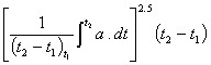
does not exceed 700, where
- a
- is the resultant acceleration at the centre of gravity of the head expressed as a multiple of g,
- g
- is the acceleration due to gravity, and
- t1 and t2
- are any two points in time during the impact, expressed in seconds, that are separated by an interval of not more than 15 ms;
(c) compression deflection of the sternum relative to the spine of the upper thorax of each anthropomorphic test device
(i) shall not exceed 50 mm, or
(ii) in the case of a vehicle with a GVWR greater than 2 722 kg, shall not exceed 60 mm; and
(d) the axially transmitted force through each upper leg of each anthropomorphic test device shall not exceed 10 kN.
(23) Subject to subsection (23.1), when a vehicle is tested, it shall be tested
(a) in accordance with the conditions set out in Test Method 208 — Occupant Restraint Systems in Frontal Impact (December 1996);
(b) by impacting a fixed collision barrier that is at 90° ± 5° to the line of travel of the vehicle while the vehicle is travelling longitudinally forward at any speed up to and including 48 km/h; and
(c) with an anthropomorphic test device that complies with the Code of Federal Regulations of the United States, title 49, part 572, subpart E (October 1994) placed at each front outboard designated seating position and secured by the seat belt assembly at that position.
(23.1) For the purposes of paragraph (23)(a), when a three-wheeled vehicle is tested, it shall be loaded in accordance with paragraph S2.2.1 of Test Method 208 — Occupant Restraint Systems in Frontal Impact (December 1996).
Air Bags
(24) An air bag shall have a monitoring system that
(a) monitors and indicates its own readiness and the readiness of every air bag that has not been deactivated; and
(b) is equipped with a tell-tale visible to the driver seated in the normal driving position.
(25) Passenger cars, three-wheeled vehicles, trucks, buses and multi-purpose passenger vehicles may be equipped with a manual air bag cut-off switch to deactivate an air bag installed at the right front outboard designated seating position if
(a) the vehicle has no forward-facing designated seating position to the rear of the front designated seating positions; or
(b) the distance between the rearward surface of the front seat back and forward surface of the rear seat back is less than 720 mm, as measured in accordance with Test Method 208 — Occupant Restraint Systems in Frontal Impact (December 1996).
(26) Where a vehicle is equipped at a designated seating position with an air bag, the vehicle shall, if scheduled maintenance or replacement of the air bag is required, have a label permanently affixed within the passenger compartment of the vehicle, in letters of not less than 6 points in height stating, in both official languages, the manufacturer’s recommended maintenance or replacement schedule by
(a) month and year;
(b) vehicle distance travelled; or
(c) specified time intervals measured from the month and year stated on the compliance label or information label applied to the vehicle in accordance with these Regulations.
(27) Where a vehicle is equipped at a designated seating position with an air bag, the vehicle shall have a label or labels permanently affixed to the sun visor at that position or in a readily visible area adjacent to the sun visor, in letters of not less than 6 points in height stating, in both official languages, the following warnings:
(a) if that position is a right front outboard designated seating position,
(i) in the case of such a designated seating position with an air bag that may be deactivated by means of a manual cut-off switch, not to install a rearward-facing child restraint system or infant restraint system in that designated seating position unless the air bag is deactivated, and
(ii) in any other case, not to install a rearward-facing child restraint system or infant restraint system in that designated seating position; and
(b) not to sit unnecessarily close to the air bag.
(28) Where a vehicle is equipped at a designated seating position with an air bag, the English and French versions of the owner’s manual shall include
(a) if scheduled maintenance or replacement of the air bag is required, instructions concerning the maintenance or replacement;
(b) a description of the air bag;
(c) the warnings set out in subsection (27);
(d) the warning not to place any objects over the air bag or between the air bag and the occupant; and
(e) if the vehicle is equipped with a manual air bag cut-off switch,
(i) instructions concerning the operation of the cut-off switch,
(ii) a statement that the cut-off switch is installed only for use when a rearward-facing child restraint system or infant restraint system is installed in the right front outboard designated seating position, and
(iii) a warning about the safety consequences of using the cut-off switch in circumstances other than those referred to in subparagraph (ii).
Tension-relieving Devices
(29) Where a vehicle that has a GVWR of 4 536 kg or less is equipped at a designated seating position with a Type 2 manual seat belt assembly that has a tension-relieving device that permits the introduction of slack in the webbing of the upper torso restraint, the vehicle shall be equipped with a means that automatically cancels any slack in that webbing when
(a) the latch plate is released; or
(b) one of the following doors is opened, namely,
(i) the vehicle door closest to that position, where the assembly is at a front outboard designated seating position or a rear outboard designated seating position, and
(ii) either vehicle door that normally enables an occupant of the seating position to exit the vehicle, where the assembly is at any other designated seating position.
(30) The English and French versions of the owner’s manual for a vehicle referred to in subsection (29) shall
(a) explain the functioning of the tension-relieving device;
(b) state the maximum amount of slack, in millimetres, that is recommended by the manufacturer to be introduced into the upper torso restraint under normal conditions of use; and
(c) warn that the introduction of slack beyond the recommended amount could significantly reduce the effectiveness of the seat belt assembly in the event of an impact.
(31) Notwithstanding subsection (29), in the case of an open-body type vehicle with no doors, a tension-relieving device may be deactivated manually.
(32) Where a vehicle is tested in accordance with subsection (23) and the vehicle is equipped at a front outboard designated seating position with a seat belt assembly that has a tension-relieving device that permits the introduction of slack in the webbing of the upper torso restraint, that webbing shall be adjusted to introduce the maximum amount of slack that is recommended in the owner’s manual under normal conditions of use or, where the owner’s manual does not contain such a recommendation, to the maximum amount of slack possible.
Accessibility of Seat Belts
(33) Any seat belt assembly latch plate that is located outboard of a front outboard designated seating position of a vehicle shall be located within the outboard reach envelope, as obtained in accordance with Test Method 208 — Occupant Restraint Systems in Frontal Impact (December 1996), of either the outboard arm or inboard arm when the latch plate is in its normal stowed position.
(34) There shall be sufficient clearance between a front outboard designated seating position seat and the side of the vehicle interior to allow a clearance test block that conforms to the dimensions set out in Figure 2 of Test Method 208 — Occupant Restraint Systems in Frontal Impact (December 1996) unhindered transit to the latch plate or buckle of any seat belt assembly that is located outboard of that front outboard designated seating position.
(35) The webbing of an upper torso restraint and pelvic restraint installed in a vehicle at a front outboard designated seating position, where tested in accordance with this section and under the conditions set out in section 5 of Test Method 208 — Occupant Restraint Systems in Frontal Impact (December 1996), shall automatically retract to a stowed position
(a) in the case of a vehicle with no doors,
(i) where the seat belt assembly has no tension-relieving device, when the latch plate is released, and
(ii) where the seat belt assembly has a tension-relieving device, when the tension-relieving device is deactivated; and
(b) in any other case, when the latch plate is released and the adjacent vehicle door is in the open or closed position.
(36) The stowed position of a seat belt assembly shall, in the case of a vehicle with doors, prevent any part of the seat belt assembly from being pinched when the adjacent vehicle door is closed.
(37) Where a seat belt assembly has seat belt webbing that passes through the seat cushion or between the seat cushion and the seat back,
(a) one of the following parts, namely, the latch plate, the buckle or the webbing, shall be maintained on top of or above the seat cushion under normal conditions; and
(b) the remaining two seat belt assembly parts shall be maintained in an accessible position under normal conditions.
(38) Subsection (37) does not apply where
(a) the seat cushions are movable and movement of both the seat cushions and the seat back enables the seat back to be used for a function other than seating;
(b) the seats are removable; or
(c) the seats are movable and enable the space normally occupied by the seat to be used for a function other than seating.
(39) The buckle and latch plate referred to in subsection (37) shall not pass through any seat belt webbing guides or conduits that are provided and shall not fall behind the seat where the seat belt is completely retracted or, if the belt is non-retractable, where the belt buckle is unlatched and, in either case,
(a) the seat is moved to any position to which it is designed to be adjusted; and
(b) if the seat back is foldable, the seat back is, starting from the manufacturer’s nominal design riding position, folded forward as far as possible and then moved backward into the initial position.
(40) The inboard receptacle end of a seat belt assembly installed at a front outboard designated seating position shall be accessible without having to move the centre armrest where that armrest is in any position.
Transitional Provisions
(41) Trucks, buses and multi-purpose passenger vehicles that have a GVWR of 3 856 kg or less and an unloaded vehicle weight of 2 495 kg or less and that are manufactured before September 1, 1998 need not comply with the requirement of subsection (21).
(42) Passenger cars manufactured before September 1, 1998 need not comply with paragraph (22)(b).
(43) Passenger cars manufactured before September 1, 1999, and trucks, buses and multi-purpose passenger vehicles that have a GVWR of 3 856 kg or less and an unloaded vehicle weight of 2 495 kg or less, manufactured on or after September 1, 1998 but before September 1, 2000, need not comply with paragraph (22)(c) if, during the test referred to in subsection (23), a compression deflection of the sternum relative to the upper thorax portion of the spine of each anthropomorphic test device does not exceed 65 mm.
- SOR/78-80, s. 2; SOR/80-782, s. 2; SOR/87-578, s. 2; SOR/90-387, s. 3; SOR/93-5, s. 4; SOR/97-201, s. 5; SOR/97-447, s. 5; SOR/98-125, s. 6; SOR/98-524, s. 4(F); SOR/2002-55, s. 17; SOR/2003-272, s. 24; SOR/2006-94, s. 4(E).
Seat Belt Assemblies[SOR/95-536, s. 7(F)]
- 209
(1) [Repealed, SOR/97-447, s. 6]
(2) Every seat belt assembly with which a vehicle is equipped shall
(a) be designed for use by only one person at one time; and
(b) provide pelvic restraint designed to remain on the pelvis of the occupant under all conditions.
(3) The pelvic restraint of a Type 2 seat belt assembly that can be used without upper torso restraint shall comply with all requirements for a Type 1 seat belt assembly set out in these Regulations.
(4) Every Type 2 seat belt assembly shall provide upper torso restraint that
(a) does not shift the pelvic restraint into the abdominal region of the occupant;
(b) is designed to minimize vertical forces on the shoulders and spine of the occupant; and
(c) has hardware designed and located in the assembly to minimize the possibility of injury to the occupant.
(5) Every Type 2A shoulder belt shall comply with all requirements for a Type 2 seat belt assembly set out in these Regulations.
(6) [Repealed, SOR/87-154, s. 3]
(7) The webbing of a seat belt assembly
(a) shall have its ends protected or treated to prevent ravelling;
(b) shall not, when used in a seat belt assembly having a metal buckle for size adjustment of the assembly, pull out of the adjustment hardware at maximum size adjustment;
(c) shall be capable of moving essentially unimpeded when routed between a seat back and seat cushion and attached to a retractor located behind the seat;
(d) shall be not less than 46 mm (1.8 in.) wide except for portions that do not touch a 95th percentile adult male where the seat is in any adjustment position and the seat back is in the manufacturer’s nominal design riding position when measured under the conditions of Motor Vehicle Safety Test Methods, Section 209, Seat Belt Assemblies, approved on behalf of the Minister on February 27, 1984;
(e) shall have a breaking strength of not less than
(i) in the case of a Type 1 seat belt assembly, 26.7 kN (6,000 pounds), and
(ii) in the case of a Type 2 seat belt assembly, 22.2 kN (5,000 pounds) for the pelvic restraint and 17.8 kN (4,000 pounds) for the upper torso restraint,
(iii) [Repealed, SOR/87-154, s. 3]
when tested in accordance with the test methods referred to in paragraph (d);
(f) except as provided in subsection (29), shall not extend more than
(i) in the case of a Type 1 seat belt assembly, 20 per cent at 11.1 kN (2,500 lb.), and
(ii) in the case of a Type 2 seat belt assembly, 30 per cent at 11.1 kN (2,500 lb.) for the pelvic restraint and 40 per cent at 11.1 kN (2,500 lb.) for the upper torso restraint,
when tested in accordance with the test methods referred to in paragraph (d);
(g) shall, when subjected to abrasion in accordance with the test methods referred to in paragraph (d), have a breaking strength of not less than 75 per cent of the breaking strength specified in paragraph (e) for that type of belt assembly;
(h) shall, when exposed to the light of a carbon arc and tested in accordance with the test methods referred to in paragraph (d), have
(i) a breaking strength of not less than 60 per cent of its strength before exposure to the light, and
(ii) a colour retention not less than No. 2 on the Geometric Gray Scale published by the American Association of Textile Chemists and Colorists;
(i) shall, unless the webbing is made from material inherently resistant to micro-organisms, when subjected to micro-organisms and tested in accordance with the test methods referred to in paragraph (d) have a breaking strength of not less than 85 per cent of its strength before subjection to micro-organisms;
(j) shall not transfer colour to a crock cloth, either wet or dry, to a greater degree than Rating 3 on the AATCC Chromatic Transference Scale, developed by the American Association of Textile Chemists and Colorists in 1972, when the webbing is tested in accordance with the test methods referred to in paragraph (d); and
(k) shall not stain to a greater degree than Rating 2 on the AATCC Chromatic Transference Scale, developed by the American Association of Textile Chemists and Colorists in 1972, when tested in accordance with the test methods referred to in paragraph (d).
(8) Every strap used in a seat belt assembly to sustain restraint forces shall comply with the requirements for webbing in subsection (7) and, if the strap is made from a rigid material, it shall comply with all applicable requirements of this section.
(9) All hardware parts of a seat belt assembly that, under normal use, make contact with any person, clothing or webbing shall not have any burrs or sharp edges.
(10) Subject to subsection (11), every seat belt assembly shall include all hardware necessary for installation in a motor vehicle in accordance with SAE Recommended Practice J800c, Motor Vehicle Seat Belt Installations, November 1973, which hardware shall be designed to prevent attachment bolts and other parts from becoming disengaged from the vehicle while in service.
(10.1) Reinforcing plates or washers furnished for universal floor installation of seat belt assemblies in motor vehicles shall
(a) be made of steel, free from burrs and sharp edges on the peripheral edges adjacent to the vehicle;
(b) be at least 1.5 mm (0.06 in.) in thickness and at least 2580 mm2 (4 in.2) in projected area;
(c) have at least a 15 mm (0.6 in.) distance between any edge of the plate and the edge of the bolt hole;
(d) have all corners rounded to a radius of not less than 6 mm (0.25 in.) or cut so that no corner angle is less than 135°; and
(e) have no side less than 6 mm (0.25 in.) in length.
(11) Seat belt assemblies designed for installation in motor vehicles equipped with seat belt anchorages that do not require anchorage nuts, plates or washers need not have the hardware described in subsection (10), but shall have 7/16 — 20 UNF-2A or 1/2 — 13 UNC-2A attachment bolts or equivalent hardware.
(12) Attachment hardware of a seat belt assembly, except attachment hardware made of corrosion resistant steel containing a minimum of 11.5 per cent chromium,
(a) shall not, after being tested in accordance with the test methods referred to in paragraph (7)(d), have significant ferrous corrosion on any surface other than surfaces at peripheral edges or edges of holes in underfloor reinforcing plates and washers; or
(b) shall be protected by a coating at least as effective as
(i) in the case of attachment hardware at or near the floor, an electro-deposited coating of nickel plus chromium, or copper plus nickel plus chromium, with a service condition number of at least SC2 determined in accordance with ASTM B456-79, “Standard Specification for Electro-deposited Coatings of Copper plus Nickel plus Chromium and Nickel plus Chromium”, and
(ii) in the case of attachment hardware other than that specified in subparagraph (i), an electro-deposited coating of nickel plus chromium, or copper plus nickel plus chromium, with a service condition number of SCl determined in accordance with the ASTM standard referred to in subparagraph (i), but such hardware shall not be racked for electro-plating in locations subject to maximum stresses.
(13) When tested in accordance with applicable subsections of the test methods referred to in paragraph (7)(d)
(a) eye bolts, shoulder bolts or other bolts used to secure the pelvic restraint of a seat belt assembly to a vehicle shall withstand a force of 40 kN (9,000 pounds), except that such bolts need not withstand a force of more than 22.2 kN (5,000 pounds) if they are installed in such a manner that only one end of a seat belt assembly can be attached thereto;
(b) attachment hardware, other than bolts, designed to receive the ends of two seat belts assemblies shall withstand a tensile force not less than 26.7 kN (6,000 pounds) without fracture of any section; and
(c) a seat belt assembly having single attachment hooks of the quick-disconnect type for connecting webbing to an eye bolt shall be provided with a retaining latch or keeper which shall not move more than 2 mm (0.08 inch) in either the vertical or horizontal direction.
(14) The release mechanism of a seat belt assembly
(a) shall be a buckle or buckles readily accessible to the occupant to permit his easy and rapid removal from the assembly;
(b) shall be designed to minimize the possibility of accidental release; and
(c) if the assembly has a buckle with a release mechanism in the latched position, shall have only one opening in which the tongue can be inserted on the end of the buckle designed to receive and latch the tongue.
(15) Every Type 1 or Type 2 seat belt assembly shall, irrespective of seat adjustment position and with the seat back in the manufacturer’s nominal design driving position,
(a) be capable of adjustment to fit occupants whose dimensions and mass range from those of a fifth percentile adult female to those of a 95th percentile adult male; and
(b) have
(i) an automatic-locking retractor,
(ii) an emergency-locking retractor, or
(iii) an adjusting device that is within the reach of the occupant.
(16) [Repealed, SOR/87-154, s. 3]
(17) Surfaces of buckles, retractors and metallic parts, other than attachment hardware, of a seat belt assembly shall not, after subjection to the corrosion conditioning specified in the test methods referred to in paragraph (7)(d), have any ferrous or non-ferrous corrosion which may be transferred, either directly or by means of the webbing, to the occupant or his clothing when the assembly is worn.
(18) Every buckle that is subjected to the conditions in subsection (17) shall meet the applicable requirements of subsections (20), (21) and (22).
(19) Plastic or other non-metallic hardware parts of a seat belt assembly shall not, when subjected to the temperature conditioning specified in the test methods referred to in paragraph (7)(d), warp or otherwise deteriorate in such a manner as to cause the assembly to operate improperly or fail to comply with applicable requirements of this section.
(20) Every buckle of a seat belt assembly
(a) shall release when a force of not more than 133 N (30 lb.) is applied as specified in the test methods referred to in paragraph (7)(d);
(b) shall not release under a compressive force of 1 780 N (400 lb.) applied as specified in the test methods referred to in paragraph (7)(d), but shall be operable and able to meet the applicable requirements of subsections (27) and (28) after the compressive force is removed;
(c) that is actuated
(i) by a push button shall have a minimum push button area of 450 mm2 with a minimum linear dimension of 10 mm for applying the release force,
(ii) by a lever shall permit the insertion of a cylinder 10 mm (0.4 in.) in diameter and 38 mm (1.5 in.) in length to at least the midpoint of the cylinder along its length in the actuation portion of the buckle release, and
(iii) by other means shall have adequate access for two or more fingers to actuate release; and
(d) having tilt lock adjustment shall lock the webbing at an angle of not less than 30° between the base of the buckle and the anchor webbing when tested in accordance with the test methods referred to in paragraph (7)(d).
(21) The force required to decrease the size of a seat belt assembly shall not exceed 49 N (11 pounds) when measured in accordance with the test methods referred to in paragraph (7)(d).
(22) The buckle latch of a seat belt assembly, when tested in accordance with the test methods referred to in paragraph (7)(d), shall not fail, gall or wear to an extent that normal latching and unlatching is impaired and, if metal to metal, shall release when in any position of partial engagement and subjected to a force of not more than 22 N (5 lb.).
(23) A non-locking retractor with which a seat belt assembly is equipped shall
(a) allow the webbing of that seat belt assembly to extend within 6 mm (0.25 inch) of maximum length when a tension is applied, as specified in the test methods referred to in paragraph (7)(d); and
(b) when on an upper-torso restraint,
(i) be attached to the non-adjustable end of the assembly,
(ii) have the reel easily visible to an occupant while wearing the assembly, and
(iii) have a maximum retraction force of not more than 4.9 N (1.1 pounds) in any strap or webbing that makes contact with the shoulder of an occupant when measured in accordance with the test methods referred to in paragraph (7)(d), unless the retractor is attached to the free end of the webbing which is not subjected to any tension during restraint of an occupant by the assembly.
(24) An automatic-locking retractor with which a seat belt assembly is equipped, when tested in accordance with the test methods referred to in paragraph (7)(d),
(a) shall not allow the webbing of that seat belt assembly to move more than 25 mm (one inch) between locking positions of the retractor;
(b) shall have a retraction force under zero acceleration of not less than 2.6 N (0.6 pound) when attached to a pelvic restraint and not less than 2 N (0.45 pound) or more than 4.9 N (1.1 pounds) in any strap or webbing that makes contact with the shoulder of an occupant when the retractor is attached to an upper torso restraint; and
(c) shall not, when attached to an upper torso restraint, increase the restraint on the occupant of the seat belt assembly during use in a vehicle travelling over rough roads.
(25) An emergency-locking retractor of a Type 1 or Type 2 seat belt assembly, when tested in accordance with the test methods referred to in paragraph (7)(d),
(a) shall lock before the webbing extends 25 mm (one inch) when the retractor is subjected to an acceleration of 0.7 times the acceleration due to gravity;
(b) shall not lock,
(i) if the retractor is sensitive to webbing withdrawal, before the webbing extends 50 mm (two inches) when the retractor is subjected to an acceleration of not more than 0.3 times the acceleration due to gravity, and
(ii) if the retractor is sensitive to vehicle acceleration, when the retractor is rotated in any direction to any angle of 15 degrees or less from its orientation in the vehicle; and
(c) shall exert a retractive force of
(i) at least 2.6 N (0.6 pound) under zero acceleration when attached only to a pelvic restraint,
(ii) not less than 0.9 N (0.2 pound) or more than 4.9 N (1.1 pounds) under zero acceleration when attached only to an upper torso restraint, and
(iii) not less than 0.9 N (0.2 pound) or more than 6.7 N (1.5 pounds) under zero acceleration when attached to a strap or webbing that restrains both the upper torso and the pelvis.
(26) A retractor used on a seat belt after subjection to the cycling procedure specified in the test methods referred to in paragraph (7)(d) shall meet the applicable requirements of subsections (23), (24), (25), (27) and (28), except that the retraction force shall not be less than 50 per cent of its original retraction force.
(27) Except as provided in subsection (29), the components of every Type 1 seat belt assembly, including webbing, straps, buckles, adjustment hardware, attachment hardware and retractors, when tested in accordance with the test methods referred to in paragraph (7)(d), shall meet the following requirements:
(a) each structural component of the seat belt assembly shall withstand a force of not less than 11.1 kN (2,500 pounds);
(b) the length of the seat belt assembly loop between anchorages shall increase by not more than 360 mm (14 inches) when subjected to a force of 22.2 kN (5,000 pounds);
(c) webbing cut by the hardware during the test shall have a breaking strength, at the cut, of not less than 18.7 kN (4,200 pounds); and
(d) there shall be no complete fracture through any solid section of metal attachment hardware during the test.
(28) Except as provided in subsection (29), the components of every Type 2 seat belt assembly, including webbing, straps, buckles, adjustment hardware, attachment hardware and retractors, when tested in accordance with the test methods referred to in paragraph (7)(d), shall meet the following requirements:
(a) the structural components in the pelvic restraint shall withstand a force of not less than 11.1 kN (2,500 pounds);
(b) the length of the pelvic restraint between anchorages shall increase by not more than 500 mm (20 inches) when subjected to a force of 11.1 kN (2,500 pounds);
(c) the structural components in the upper torso restraint shall withstand a force of not less than 6 670 N (1,500 pounds);
(d) the length of the upper torso restraint between the anchorages shall increase by not more than 500 mm (20 inches) when subjected to a force of 6 670 N (1,500 pounds);
(e) the structural components in the assembly that are common to both pelvic and upper torso restraint shall withstand a force of not less than 13.3 kN (3,000 pounds);
(f) webbing cut by the hardware during the test shall have a breaking strength of not less than
(i) 15.6 kN (3,500 pounds) at a cut in the webbing of the pelvic restraint, or
(ii) 12.5 kN (2,800 pounds) at a cut in the webbing of the upper torso restraint; and
(g) there shall be no complete fracture through any solid section of metal attachment hardware during the test.
(29) A Type 1 or Type 2 seat belt assembly that includes a load-limiter
(a) is not required to comply with the elongation requirements of paragraph (7)(f), (27)(b), (28)(b) or (28)(d); and
(b) where the seat belt assembly does not comply with the elongation requirements of paragraph (7)(f), (27)(b), (28)(b) or (28)(d), shall
(i) not be installed in a vehicle except in conjunction with an air bag, and
(ii) in addition to conforming to the marking requirements specified in subsection (30), be permanently and legibly marked or labelled with a statement that the seat belt assembly may be installed in a vehicle only in conjunction with an air bag.
“This seat belt assembly may be installed in a vehicle only in combination with an automatic restraint system such as an air cushion or an automatic belt.”
(30) Every seat belt assembly shall be permanently and legibly marked or labelled with
(a) the year of manufacture;
(b) the name or trademark of the manufacturer, distributor, or importer; and
(c) the model identification.
(31) For the purpose of paragraph (30)(c), a model shall consist of a single combination of webbing having a specific type of fibre weave and construction, and hardware having a specific design although various colours may be included in the same model.
(32) Every vehicle equipped with a seat belt assembly shall be provided with
(a) written instructions regarding
(i) the proper use of the assembly, stressing the importance of wearing the assembly snugly and properly located on the body,
(ii) the maintenance of the assembly and periodic inspection of all components, and
(iii) the proper manner of threading the webbing in the hardware of seat belt assemblies in which the webbing is not permanently fastened;
(b) in the case of a non-locking retractor, a caution that the webbing must be fully extended from the retractor during use of the seat belt assembly unless the retractor is attached to the free end of the webbing that is not subjected to any tension during restraint of an occupant by the assembly; and
(c) in the case of a Type 2A assembly, a warning that the shoulder belt is not to be used without a lap belt.
- SOR/78-910, s. 2; SOR/87-154, s. 3; SOR/92-545, s. 4; SOR/97-447, s. 6.
Seat Belt Anchorages (Standard 210)
General
- 210
(1) Subject to subsection (2), seat belt anchorages shall be installed for each designated seating position in a vehicle for the following types of seat belt assemblies:
(a) a Type 2 manual seat belt assembly where required by section 208; and
(b) in any other case, a Type 1 or Type 2 manual seat belt assembly.
(2) Seat belt anchorages need not be installed for a passenger seat in a bus.
(2.1) Only the strength test requirements set out in subsections (7) to (10) apply to enclosed motorcycles.
Anchorage Positioning Requirements
(3) A seat belt anchorage for the pelvic portion of a seat belt assembly shall be located at least 165 mm laterally from the other seat belt anchorage of that seat belt, as measured between the vertical centrelines of the bolt holes or, in designs using another means of attachment to the vehicle structure, the centroids of such means.
(4) In the case of a seat belt assembly in which
(a) the seat belt passes outside the seat or between the seat cushions without bearing on the seat structure, as illustrated in Figure 1 of SAE Recommended Practice J383 (June 1995), a line from
(i) in the case of a seat that has no travel, the seating reference point,
(ii) in the case of a seat with a travel of not more than 70 mm, where the travel is intended for use by an occupant, the H-point with the seat in its rearmost position within that range of travel, or
(iii) in the case of a seat with a travel of more than 70 mm, a point 63.5 mm to the fore of, and 9.5 mm above, the seating reference point
to the nearest contact point of the belt with the seat belt anchorage shall extend to the fore from that contact point at an angle to the horizontal of not less than 30° and not more than 75°;
(b) the seat belt bears on the seat structure, as illustrated in Figure 3 of SAE Recommended Practice J383 (June 1995),
(i) the seat belt anchorage shall be aft of the rearmost contact point of the belt on the seat frame with the seat in its rearmost position, and
(ii) the line from the seating reference point to the nearest contact point of the seat belt with the seat frame shall extend to the fore from that contact point at an angle to the horizontal of not less than 30° and not more than 75°; and
(c) the seat belt anchorage is on the seat structure, the line from the seating reference point to the nearest contact point of the belt with the anchorage shall extend to the fore from that contact point at an angle to the horizontal of not less than 30° and not more than 75°.
(5) In the case of each non-adjustable seat belt anchorage for the upper end of an upper torso restraint, the intersection of the longitudinal centreline of the bolt hole and the surface of the mounting structure or, in designs using another means of attachment to the vehicle structure, the centroid of such means shall be located within the range indicated in section 6.1 of SAE Recommended Practice J383 (June 1995), with reference to an H-point template described in section 3 of SAE Standard J826 (June 1992), where
(a) the H-point of the template is located at the unique Design H-point of the seat, as defined in section 2.2.11.1 of SAE Recommended Practice J1100 (June 1993), at the full rearward and full downward position of the seat; and
(b) the torso line of the template is at the same angle to the vertical plane as the seat back with the seat adjusted to its full rearward and full downward position and the seat back in its most upright position.
(6) In the case of each adjustable seat belt anchorage for the upper end of an upper torso restraint, the mid-point of the range of adjustment of the anchorage or the position that is suitable for a 50th percentile adult male, if that position is specified in the owner’s manual, shall be located within the range referred to in subsection (5).
Strength Requirements
(7) Except in the case of side-facing seats, when the seat belt anchorages for a Type 1 manual seat belt assembly or for the pelvic portion of a Type 2 manual seat belt assembly that is equipped with a detachable upper torso restraint are tested for strength in accordance with Test Method 210 — Seat Belt Anchorages (December 1996) by applying a force of 22 240 N, none of the seat belt anchorages shall separate completely from the vehicle structure or seat structure.
(8) When the seat belt anchorages for the pelvic portion and for the upper torso portion of a Type 2 manual seat belt assembly are tested for strength in accordance with Test Method 210 — Seat Belt Anchorages (December 1996) by simultaneously applying a force of 13 344 N, none of the seat belt anchorages shall separate completely from the vehicle structure or seat structure.
(9) [Repealed, SOR/2003-57, s. 1]
(10) Seat belt anchorages for designated seating positions that face in the same direction shall be tested by simultaneously loading the seat belt assemblies attached to the anchorages, where the anchorages are
(a) common to the same seat; or
(b) laterally adjacent but not common to the same seat and at least one of the anchorages is located within 304.8 mm of the anchorage for the adjacent seating position, as measured between the vertical centrelines of the bolt holes or, in designs using another means of attachment to the vehicle structure, the centroids of such means.
Information Respecting Restraint Systems
(11) The English and French versions of the owner’s manual for a three-wheeled vehicle, passenger car, multi-purpose passenger vehicle or truck with a GVWR of not more than 4 536 kg and rear designated seating positions shall contain a statement indicating that children and infants are safer when properly restrained in a child restraint system or infant restraint system secured in a rear seating position.
- SOR/90-588, s. 3; SOR/93-5, s. 5; SOR/97-447, s. 7; SOR/2003-57, ss. 1, 3(F), 4(F); SOR/2003-272, s. 25; SOR/2006-94, s. 4(E).
User-ready Tether Anchorages for Restraint Systems (Standard 210.1)
Application
- 210.1
(1) Subject to subsection (2), this section applies to every
(a) passenger car;
(b) three-wheeled vehicle;
(c) multi-purpose passenger vehicle and truck with a GVWR of 3 856 kg or less and an unloaded vehicle weight of 2 495 kg or less;
(d) school bus; and
(e) bus, other than a school bus, with a GVWR of 4 536 kg or less.
(2) This section does not apply to
(a) a convertible;
(b) an open-body type vehicle; or
(c) a designated seating position at which a built-in child restraint system is provided that is not part of a removable vehicle seat.
General
(3) Subject to subsections (3.2) and (3.3), a user-ready tether anchorage shall be installed
(a) for each forward-facing designated seating position, other than that of the driver, in a vehicle that has only one row of forward-facing designated seating positions;
(b) for each forward-facing designated seating position in the second row of seating positions in a passenger car, three-wheeled vehicle or truck;
(c) for each of any two forward-facing designated seating positions in the second row of seating positions in a multi-purpose passenger vehicle that has five or fewer designated seating positions;
(d) for each of any three forward-facing designated seating positions that are located to the rear of the first row of designated seating positions in a multi-purpose passenger vehicle that has six or more designated seating positions;
(e) for each of any two forward-facing designated seating positions, other than that of the driver or those of a bench seat that contains an adjacent seat in relation to the emergency exit, in a school bus that has 24 or fewer designated passenger seating positions;
(f) for each of any four forward-facing designated seating positions, other than that of the driver or those in a bench seat that contains an adjacent seat in relation to the emergency exit, in a school bus that has 25 or more, but 65 or fewer, designated passenger seating positions;
(g) for each of any eight forward-facing designated seating positions, other than that of the driver or those in a bench seat that contains an adjacent seat in relation to the emergency exit, in a school bus that has 66 or more designated passenger seating positions; and
(h) for each of any two forward-facing designated seating positions, other than that of the driver, in a bus other than a school bus.
(3.1) A user-ready tether anchorage shall be available for use at all times, except when the seating position for which it is installed is not available for use because the vehicle seat has been removed or converted to an alternate use such as the carrying of cargo.
(3.2) A truck that has no forward-facing designated seating position in the second row of seating positions is not required to be equipped with a user-ready tether anchorage before September 1, 2004.
(3.3) If a lower universal anchorage system is installed in a designated passenger seating position in the first row of designated seating positions in accordance with subsection 210.2(8) one user-ready tether anchorage shall be installed in that designated seating position.
(3.4) The number of user-ready tether anchorages required in the second row of designated seating positions under subsection (3) may be reduced by one if a user-ready tether anchorage is installed in the first row in accordance with subsection (3.3).
(4) The portion of a user-ready tether anchorage that is designed to bind with the tether strap hook shall be readily accessible and, if under a cover, the cover shall be identified by one of the symbols or the mirror image of one of the symbols set out in Figure 2 and shall be removable without the use of tools.
Tether Anchorage Positioning
(5) Subject to subsections (5.1), (6) and (7), the portion of each user-ready tether anchorage that is designed to bind with a tether strap hook shall be located within the shaded zone, as shown in Figures 3 to 7, of the designated seating position for which it is installed, with reference to the H-point of a template described in section 3.1 of SAE Standard J826 (June 1992), if
(a) the H-point of the template is located
(i) at the unique Design H-point of the designated seating position, as defined in section 2.2.11.1 of SAE Recommended Practice J1100 (June 1993), at the full downward and full rearward position of the seat, or
(ii) in the case of a designated seating position that is equipped with a lower universal anchorage system, midway between the two lower universal anchorage system bars;
(b) the torso line of the template is at the same angle to the vertical plane as the vehicle seat back with the seat adjusted to its full rearward and full downward position and the seat back in its most upright position; and
(c) the template is positioned in the vertical longitudinal plane that contains the H-point of the template.
(5.1) In the case of a bus, no portion of the user-ready tether anchorage shall be located on the bus floor.
(6) Until September 1, 2004, the portion of each user-ready tether anchorage that is designed to bind with the tether strap hook may be located, in a passenger car, three-wheeled vehicle or multi-purpose passenger vehicle, within the shaded zone, as shown in Figures 8 to 11, of the designated seating position for which it is installed, with reference to the shoulder reference point of a template described in section 3.1 of SAE Standard J826 (June 1992), if
(a) the H-point of the template is located
(i) at the unique Design H-point of the designated seating position, as defined in section 2.2.11.1 of SAE Recommended Practice J1100 (June 1993), at the full downward and full rearward position of the seat, or
(ii) in the case of a designated seating position that is equipped with a lower universal anchorage system, midway between the two lower universal anchorage system bars;
(b) the torso line of the template is at the same angle to the vertical plane as the vehicle seat back with the seat adjusted to its full rearward and full downward position and the seat back in its most upright position; and
(c) the template is positioned in the vertical longitudinal plane that contains the H-point of the template.
(7) The portion of a user-ready tether anchorage in a vehicle that is designed to bind with the tether strap hook may be located outside the shaded zone referred to in subsection (5), if no part of the shaded zone is accessible without removing a seating component of the vehicle and the vehicle is equipped with a routing device that
(a) ensures that the tether strap functions as if the portion of the anchorage designed to bind with the tether strap hook were located within the shaded zone;
(b) is at least 65 mm behind the torso line, in the case of a non-rigid-webbing-type routing device or a deployable routing device, or at least 100 mm behind the torso line, in the case of a fixed rigid routing device; and
(c) when tested after being installed as it is intended to be used, is of sufficient strength to withstand, with the user-ready tether anchorage, the load referred to in subsection (8) or (9), as applicable.
Strength Requirements
(8) Subject to subsections (9) and (10), every user-ready tether anchorage in a row of designated seating positions shall, when tested, withstand the application of a force of 10 000 N
(a) applied by means of one of the following types of test devices, installed as a child restraint system would be in accordance with the manufacturer’s installation instructions, namely,
(i) a test device shown in Figures 12 to 16, or
(ii) a test device shown in Figures 7 and 8 of section 210.2, in the case of a designated seating position having a lower universal anchorage system;
(b) applied
(i) in a forward direction parallel to the vehicle’s vertical longitudinal plane through the X point on the test device, and
(ii) initially, along a line above the horizontal line, at an angle of 10° ± 5° to it.
(c) attained within 30 seconds, at any onset force rate of not more than 135 000 N/s; and
(d) maintained at a 10 000-N level for a minimum of one second.
(9) Until September 1, 2004, every user-ready tether anchorage in a row of designated seating positions in a passenger car or three-wheeled vehicle may, when tested, subject to subsection (10), withstand the application of a force of 5 300 N, which force shall be
(a) applied by means of a belt strap that
(i) extends not less than 250 mm forward from the vertical plane touching the rear top edge of the vehicle seat back,
(ii) is fitted at one end with suitable hardware for applying the force and at the other end with a bracket for the attachment of the user-ready tether anchorage, and
(iii) passes over the top of the vehicle seat back as shown in Figure 19;
(b) applied
(i) in a forward direction parallel to the vehicle’s longitudinal vertical plane, and
(ii) initially, along a horizontal line or along any line below that line that is at an angle to that line of not more than 20°;
(c) attained within 30 seconds, at any onset force rate of not more than 135 000 N/s; and
(d) maintained at a 5 300-N level for a minimum of one second.
(10) If the zones in which tether anchorages are located overlap and if, in the overlap area, a user-ready tether anchorage is installed that is designed to accept the tether strap hooks of two restraint systems simultaneously, both portions of the tether anchorage that are designed to bind with a tether strap hook shall withstand the force referred to in subsection (8) or (9), as the case may be, applied to both portions simultaneously.
(11) If a bench seat in a bus or a row of designated seating positions in another vehicle has more than one user-ready tether anchorage and a distance of 400 mm or more, measured in accordance with Figure 20, separates the midpoints of adjacent designated seating positions, the force referred to in subsection (8), (9) or (10), as the case may be, shall be applied simultaneously to each user-ready tether anchorage in the manner specified in that subsection.
(12) The strength requirement tests shall be conducted with the vehicle seat adjusted to its full rearward and full downward position and the seat back in its most upright position.
Figures 1 to 20
GRAPHIC IS NOT DISPLAYED, SEE SOR/98-457, S. 3; SOR/2000-44, SS. 2, 3; SOR/2002-205, S. 3; SOR/2003-272, S. 26
- SOR/86-975, s. 2; SOR/92-545, s. 5; SOR/94-669, s. 3; SOR/95-536, s. 7; SOR/98-457, s. 3; SOR/2000-44, ss. 1 to 3; SOR/2002-205, s. 3; SOR/2003-272, s. 26; SOR/2006-94, ss. 2, 4(E).
Lower Universal Anchorage Systems for Restraint Systems and Booster Cushions (Standard 210.2)
Application
- 210.2
(1) Subject to subsection (2), this section applies to every
(a) passenger car;
(a.1) three-wheeled vehicle;
(b) multi-purpose passenger vehicle and truck with a GVWR of 3 856 kg or less and an unloaded vehicle weight of 2 495 kg or less;
(c) bus, other than a school bus, with a GVWR of 4 536 kg or less; and
(d) school bus.
(2) This section does not apply to
(a) a walk-in van;
(b) a bus that has only one row of forward-facing designated seating positions rearward of the driver’s seat;
(c) a vehicle that is not equipped with a manual cut-off switch to deactivate the frontal air bag that is installed at the right front outboard designated seating position when any restraint system or booster cushion is installed and
(i) has only one row of forward-facing designated seating positions,
(ii) cannot accommodate, because of the location of transmission or suspension components, the installation of the bars of a lower universal anchorage system to permit the attachment to them of a child restraint fixture as shown in Figure 1 in a seating position located to the rear of the first row of seating positions, or
(iii) has no seating position located to the rear of the first row of seating positions that is able to accommodate a child restraint fixture shown in Figures 2 to 4.
General
(3) A lower universal anchorage system consists of two straight horizontal bars that
(a) are transverse to the longitudinal axis of the vehicle;
(b) have a diameter of 6 mm ± 0.1 mm and a length of not less than 25 mm;
(c) are parallel, with collinear centroidal longitudinal axes, and are spaced laterally so that they permit the lower connectors on a child restraint fixture, shown in Figures 2 to 4, to be attached to them over the entire length of the lower connectors;
(d) are an integral and permanent part of a vehicle seat or seat anchorage or the structure of the vehicle such that they can be removed only with the use of tools;
(e) are rigidly attached to a vehicle seat or seat anchorage or the structure of the vehicle so that they will not deform more than 5 mm when subjected to a force of 100 N in any direction with the vehicle seat adjusted in the vehicle to its full rearward and full downward position and the seat back adjusted in the nominal design riding position; and
(f) permit a checking device to be attached to them over the entire width of the checking device, with a gap of less than 1 mm between the surface of the bars and line M, shown in Figure 5.
(4) Subject to subsections (7) and (8), a lower universal anchorage system shall be installed
(a) in one forward-facing designated seating position, other than that of the driver, in a vehicle that has only one row of forward-facing designated seating positions;
(b) in each of any two forward-facing designated seating positions in the second row of seating positions in a passenger car, three-wheeled vehicle or truck;
(c) in each of two forward-facing designated seating positions that are located to the rear of the first row of seating positions in a multi-purpose passenger vehicle that has more than two rows of seating positions, but at least one lower universal anchorage system must be installed in a seating position in the second row of seating positions;
(d) for each of any two forward-facing designated seating positions, other than that of the driver or those in a bench seat that contains an adjacent seat in relation to the emergency exit, in a school bus that has 24 or fewer designated passenger seating positions;
(e) for each of any four forward-facing designated seating positions, other than that of the driver or those in a bench seat that contains an adjacent seat in relation to the emergency exit, in a school bus that has 25 or more, but 65 or fewer, designated passenger seating positions;
(f) for each of any eight forward-facing designated seating positions, other than that of the driver or those in a bench seat that contains an adjacent seat in relation to the emergency exit, in a school bus that has 66 or more designated passenger seating positions; and
(g) for each of any two forward-facing designated seating positions, other than that of the driver, in a bus other than a school bus.
(5) Despite paragraph 4(a), a truck that has no forward-facing designated seating position in the second row of seating positions is not required to be equipped with a lower universal anchorage system before September 1, 2004.
(6) A lower universal anchorage system may be installed only at a designated seating position that is equipped with a user-ready tether anchorage, except in the case of a convertible.
(7) The number of lower universal anchorage systems required in a vehicle under subsection (4) may be reduced by the number of built-in child restraint systems installed in the vehicle.
(8) Except in the case of a bus, if the distance between the rearward surface of the front seat back and the forward surface of the rear seat back is less than 720 mm, as measured in accordance with Figure 6, a lower universal anchorage system may be installed in a designated passenger seating position in the first row of designated seating positions instead of in the second row of designated seating positions if the vehicle is equipped with the manual cut-off switch referred to in paragraph (2)(c).
(9) A vehicle that is equipped with a seat that slides sideways or that can be installed in any other seating position in the vehicle shall meet the requirements of this section with the seat adjusted in any adjustment position.
(10) Until August 31, 2006, a lower universal anchorage system may consist of horizontal bars that are foldable.
Lower Universal Anchorage System Positioning
(11) Each bar of the lower universal anchorage system shall be installed so that a child restraint fixture can be attached to the system as shown in Figure 1.
(12) For the purposes of subsection (11), the vehicle seat shall be adjusted to its full rearward and full downward position, with the seat back in the nominal design riding position and the child restraint fixture shown in Figures 2 and 3 or in Figure 4 installed in the seat.
Strength Requirements
(13) A lower universal anchorage system installed in a row of designated seating positions shall not separate completely from the vehicle seat or seat anchorage or the structure of the vehicle when tested
(a) by pulling with a force of 15 000 N, which force is
(i) applied by means of a test device shown in Figures 7 and 8 that is installed using both the user ready tether anchorage and the lower universal anchorage system as a child restraint system would be installed in accordance with the vehicle manufacturer’s instructions,
(ii) applied in a forward direction parallel to the vehicle’s vertical longitudinal plane through the X point on the test device, starting with a pre-load force of 500 N, maintained for at least two minutes but not more than five minutes,
(iii) applied initially, along a line above the horizontal line, at an angle of 10° ± 5° to it,
(iv) attained within 30 seconds, at any onset force rate of not more than 135 000 N/s, and
(v) maintained at a level of 15 000 N for a minimum of one second; and
(b) by pulling with a force of 5 000 N, which force is
(i) applied by means of a test device shown in Figures 7 and 8 that is installed as a child restraint system would be installed in accordance with the vehicle manufacturer’s instructions using both the user ready tether anchorage and the lower universal anchorage system or, at the manufacturer’s option, using only the lower universal anchorage system,
(ii) applied along a vertical longitudinal plane that is at an angle of 75° ± 5° to either side of a vertical longitudinal plane that is parallel to the vehicle’s longitudinal centre line, through the X point on the test device, starting with a pre-load force of 500 N, maintained for at least two minutes but not more than five minutes,
(iii) applied initially, along a horizontal line or along any line below or above that line that is at an angle to that line of not more than 5°,
(iv) attained within 30 seconds, at any onset force rate of not more than 135 000 N/s, and
(v) maintained at a level of 5 000 N for a minimum of 1 second.
(14) When a force of 5 000 N is applied in accordance with paragraph (13)(b), the lower universal anchorage system shall not permit the X point on the test device to be displaced by more than 125 mm, if the test device is installed in an outboard designated seating position, or 150 mm, if the test device is installed in an inboard designated seating position.
(15) Until August 31, 2004, instead of being tested by the application of a force of 15 000 N in accordance with paragraph 13(a), a lower universal anchorage system installed in a row of designated seating positions may be tested by pulling with a force of 8 000 N ± 250 N, during the application of which it shall not separate completely from the vehicle seat or seat anchorage or the structure of the vehicle, and which is
(a) applied by means of a test device shown in Figures 7 and 8 that is installed using both the user ready tether anchorage and the lower universal anchorage system, as a child restraint system would be installed in accordance with the vehicle manufacturer’s instructions;
(b) applied in a forward direction, parallel to the vehicle’s vertical longitudinal plane through the X point on the test device, starting with a pre-load force of 500 N ± 25 N;
(c) applied initially, along a line above the horizontal line, at an angle of 10° ± 5° to it;
(d) attained within 2 seconds; and
(e) maintained at a level of 8 000 N ± 250 N for a minimum of 0.25 seconds ± 0.05 seconds.
Test Requirements
(16) If a bench seat in a bus or a row of designated seating positions in another vehicle has more than one lower universal anchorage system and a distance of 400 mm or more, measured in accordance with Figure 9, separates the midpoints of any adjacent designated seating positions, the force referred to in subsection (13) or (15) shall be applied simultaneously to each anchorage system in the manner specified in that subsection.
(17) The strength requirement tests shall be carried out under the following conditions:
(a) the vehicle seat is installed in the vehicle;
(b) the vehicle seat is adjusted to its full rearward and full downward position;
(c) the vehicle seat back is adjusted in the nominal design riding position;
(d) the head restraints, if installed at a designated seating position that is equipped with a lower universal anchorage system, are adjusted in accordance with the manufacturer’s instructions; and
(e) a rearward force of 135 N ± 15 N is applied to the centre of the lower front crossbar of the test device shown in Figures 7 and 8 to press the test device against the seat back as the position of the lower connectors of the test device is adjusted to remove slack or tension.
(17.1) Despite subsection (17), in the case of a bus, the strength requirement tests may be carried out when the vehicle seat is not installed in the vehicle if
(a) the user-ready tether anchorage is installed on the vehicle seat in accordance with the tether anchorage positioning requirements of section 210.1 for a designated seating position of the vehicle;
(b) the structure on which the seat is installed, the seat anchorage and all associated hardware are equivalent to those used when the vehicle seat is installed in the vehicle; and
(c) a rearward force of 135 N ± 15 N is applied to the centre of the lower front crossbar of the test device shown in Figures 7 and 8 to press the test device against the seat back as the position of the lower connectors of the test device is adjusted to remove slack or tension.
Information Respecting Lower Universal Anchorage Systems
(18) Subject to subsections (19), (20) and (21), if a lower universal anchorage system is not visible along a line making an upward angle of at least 30° with the horizontal plane without compression of the seat cushion or seat back of the seating position, the presence of each bar of the system shall be indicated by the symbol shown in Figure 10, consisting of a circle containing a pictogram, which symbol shall meet the following conditions:
(a) the pictogram shall contrast with the background of the circle;
(b) the circle shall contrast with its background, namely, the seat back or seat cushion of the vehicle;
(c) its centre shall be located no more than 25 mm from the vertical longitudinal plane that passes through the centre of each bar of the system;
(d) it shall be marked on the seat back or on the seat cushion of the vehicle in accordance with Figure 11; and
(e) it shall be permanently marked by any means in a manner that makes it impossible to remove without defacing or destruction.
(19) In the case of a foldable lower universal anchorage system, its presence shall be indicated by the symbol shown in Figure 10 marked in accordance with subsection (18) or marked on the mechanism for deploying each bar of the foldable system and visible at the junction of the seat back and the seat cushion when the system is in the folded position.
(20) In the case of a lower universal anchorage system hidden by one or more covers, its presence may be indicated by the symbol shown in Figure 10 marked on each cover in the following cases:
(a) the covers are not entirely removable; or
(b) the system is visible in accordance with subsection (18) if the covers are entirely removed.
(21) Until August 31, 2004, a manufacturer may
(a) replace the symbol shown in Figure 10 by a mark consisting of an inscription in letters, a drawing or a solid or open circle that contrasts with its background, namely, the seat back or seat cushion of the vehicle;
(b) show a contrast only between the seat back or seat cushion of the vehicle and the outlines of a line drawing in the form of the circle and pictogram of the symbol shown in Figure 10;
(c) indicate the presence of only one of the bars of the lower universal anchorage system in the manner provided by subsection (18) or (20); or
(d) place the mark or symbol used to indicate the presence of a lower universal anchorage system in an easily visible location on the seat back or seat cushion of the vehicle instead of in the locations specified in paragraphs 18(c) and (d).
(22) The English and French versions of the owner’s manual for a vehicle that is equipped with a lower universal anchorage system shall contain the following information:
(a) if the symbol shown in Figure 10 is marked on a seat back, seat cushion or cover over the lower universal anchorage system, an explanation that the symbol indicates the presence of a lower universal anchorage system, and a reproduction of the symbol;
(b) if, in accordance with paragraph 21(a), a mark other than the symbol shown in Figure 10 is marked on a seat back, seat cushion or cover over the lower universal anchorage system,
(i) an explanation that the mark indicates the presence of a lower universal anchorage system, and a reproduction of the mark, and
(ii) an explanation that the symbol shown in Figure 10 indicates the presence of a lower connector system on a child restraint system or booster cushion, and a reproduction of the symbol;
(c) an identification, by means of the symbol shown in Figure 10 or any other mark used to indicate the presence of a lower universal anchorage system, as applicable, of the designated seating positions that are equipped with a lower universal anchorage system;
(d) if the vehicle is equipped with a foldable system, instructions on how to deploy the system;
(e) if the vehicle is equipped with head restraints at the seating positions equipped with a lower universal anchorage system, instructions on the correct manner of adjusting the head restraints for use with user-ready tether anchorages; and
(f) if the vehicle has more than one row of designated seating positions, a statement that children and infants are safer when properly restrained in a child restraint system or infant restraint system secured in a rear seating position.
Figures 1 to 11
GRAPHIC IS NOT DISPLAYED, SEE SOR/2002-205, S. 4
- SOR/2002-205, s. 4; SOR/2003-272, s. 27; SOR/2005-342, s. 4; SOR/2006-94, ss. 3, 4(E).
211 [Repealed, SOR/97-421, s. 13]
Windshield Mounting
- 212
(1) This section does not apply to
(a) any vehicle with a GVWR in excess of 4 536 kg (10,000 lbs.); or
(b) forward control configuration vehicles, walk-in vans or open-body type vehicles with fold down or removable windshields.
(2) When a vehicle, prepared and loaded in accordance with subsections (5) to (7), travelling longitudinally forward at any speed up to and including 48 km/h (30 mph), impacts a fixed collision barrier perpendicular to the line of travel of the vehicle, the windshield mounting of the vehicle shall, when tested in accordance with subsection (8), retain not less than the minimum portion of the windshield periphery specified in subsection (3) or (4), whichever is applicable.
(3) For the purposes of subsection (2), a vehicle that meets the requirements of section 208 and is equipped with an air bag at a front designated seating position shall retain not less than 50 per cent of the windshield periphery on each side of the vehicle longitudinal centre line.
(4) For the purposes of subsection (2), a vehicle that meets the requirements of section 208 but is not equipped with an air bag at a front designated seating position shall retain not less than 75 per cent of the windshield periphery.
(5) A passenger car shall be loaded to its unloaded vehicle mass, which shall include the test devices and instrumentation mass, except for the fuel system, which shall be filled as specified in subsection (6) and, in addition, the vehicle shall have
(a) the vehicle cargo and luggage capacity mass secured in the luggage area; and
(b) the appropriate number of anthropomorphic test devices, as specified in paragraph (7)(a), restrained only by means that are installed in the vehicle for protection at their seating positions.
(5.1) A multi-purpose passenger vehicle, truck or bus, with the test devices and instrumentation included in its unloaded vehicle mass and the fuel tank filled as specified in subsection (6), shall be loaded to its unloaded vehicle mass or 2 500 kg (5,500 lbs), whichever is the lesser, except that the mass shall not include the mass of any work-performing accessories but the following shall be added to the load:
(a) the vehicle rated cargo and luggage capacity mass or 140 kg (300 lbs), whichever is the lesser, secured to the vehicle and distributed so that the mass on each axle as measured at the tire-ground interface is in proportion to its GAWR, except that if the mass on any axle when the vehicle is loaded to its unloaded vehicle mass plus the anthropomorphic test device mass exceeds the axle’s proportional share of the test mass, the remaining mass shall be placed so that the mass on that axle remains the same; and
(b) the appropriate number of anthropomorphic test devices, as specified in paragraph (7)(a), restrained only by means that are installed in the vehicle for protection at their seating positions.
(6) The fuel tank of a vehicle referred to in subsection (5) shall be filled to any level from 90 to 95 per cent of capacity with Stoddard solvent, having the physical and chemical properties of type 1 solvent, Table 1 American Society for Testing and Materials Standard D484-71, Standard Specifications for Hydrocarbon Dry Cleaning Solvents.
(7) For the purposes of subsection (2),
(a) a 50th percentile adult male anthropomorphic test device shall be provided at each front outboard seating position and at any other seating position whose protection system is required to be tested using an anthropomorphic test device under the frontal impact protection provision of section 208;
(b) the parking brake shall be disengaged and the transmission shall be in neutral; and
(c) the tires shall be inflated to the manufacturer’s specifications.
(8) For the purposes of subsection (2), the test shall be conducted on the windshield mounting material and all vehicle components in direct contact with the mounting material at any temperature between -9°C (15°F) and 43°C (110°F).
- SOR/80-282, s. 3; SOR/82-274, s. 1; SOR/90-387, s. 2(F); SOR/93-5, s. 6; SOR/94-692, s. 2(F); SOR/95-536, s. 7(F); SOR/97-201, s. 5; SOR/97-421, ss. 17, 22(F); SOR/2003-57, s. 2.
213. to 213.3 [Repealed, SOR/98-160, s. 3]
Built-in Child Restraint Systems and Built-in Booster Cushions
- 213.4
(1) Every built-in child restraint system and built-in booster cushion, when tested in accordance with Motor Vehicle Test Methods, Section 213.4, “Built-in Child Restraint System and Built-in Booster Cushion” (October 15, 1993) in any of the positions that the system, cushion, or vehicle seat can be used while the vehicle is in motion, shall,
(a) exhibit no complete separation of any load bearing structural element and no partial separation exposing either surfaces that have a radius of less than 6.4 mm (1/4 inch) or surfaces that have protrusions greater than 9.5 mm (3/8 inch) above the immediate adjacent surrounding contactable surface of any structural element of the system;
(b) remain in the same adjustment position during the testing as it was immediately before the testing began, where the system is adjustable to different positions; and
(c) be constructed only of materials that conform to the requirements of section 302.
(2) Every built-in child restraint system when tested in accordance with subsection (1) shall, subject to subsection (6), provide restraint against rearward movement of the head of the child by means of a continuous seat back that is an integral part of the system and that has
(a) a height, measured along the system seat back surface for the child in the vertical longitudinal plane passing through the longitudinal centre line of the child restraint system from the lowest point on the system seating surface that is contactable by the buttocks of the seated anthropometric test device, of at least 500 mm (20 inches); and
(b) a width of not less than 200 mm (8 inches), measured in the horizontal plane at the height of 500 mm (20 inches) specified in paragraph (a).
(3) Every built-in rear facing child restraint system, when tested in accordance with subsection (1) shall
(a) not allow the angle between the system’s back support surface and the vertical to exceed 70° at any time during impact simulation; and
(b) retain all portions of the anthropometric test device within the system so that no portion of the target point on either side of the device’s head passes through the transverse orthogonal planes whose intersection contains the forward-most and top-most points on the built-in child restraint system surfaces.
(4) Every built-in booster cushion, when tested in accordance with subsection (1) shall
(a) subject to subsection (6), provide restraint against rearward movement of the head of the child by means of a continuous seat back that is an integral part of the cushion and that
(i) has a height, measured along the cushion seat back surface in the vertical longitudinal plane passing through the longitudinal centre line of the cushion from the lowest point on the cushion seating surface that is contactable by the buttocks of the seated anthropometric test device, of at least 560 mm (22 inches), and
(ii) has a width of not less than 200 mm (8 inches), measured in the horizontal plane at the height of 560 mm (22 inches) specified in subparagraph (i); and
(b) limit to no more than 305 mm (12 inches) from the initial position the distance either knee pivot can extend in the forward longitudinal direction.
(5) Every front-facing built-in child restraint system and built-in booster cushion, when tested in accordance with subsection (1), shall
(a) not allow the angle between the system’s or cushion’s back support surface and the system’s or cushion’s seating surface to be less than 45° at the completion of the test;
(b) limit the resultant acceleration at the location of the accelerometer mounted in the anthropometric test device upper thorax to not more than 60 g, except for intervals of acceleration the cumulative duration of which is not more than 3 ms;
(c) limit to not more than 80 g the maximum resultant acceleration of the centre of gravity of the head of the anthropometric test device during forward movement, except where it has been established that the maximum resultant acceleration above 80 g is caused by another part of the anthropometric test device striking its head; and
(d) subject to subsection (6), provide restraint against rearward movement of the head of the child by means of a continuous seat back that is an integral part of the system and that limits the rearward rotation of the anthropometric test device’s head so that the angle between the head and the torso is at no time during the impact testing greater than 45° as compared to the head-torso angle prior to the test.
(6) Notwithstanding the requirements of paragraph (2)(a), a built-in child restraint system with side supports extending at least 100 mm (4 inches) forward from the padded surface of the portion of the restraint system provided for support of the child’s head shall have a width of not less than 150 mm (6 inches), measured in the horizontal plane at the height of 500 mm (20 inches).
(7) Every built-in child restrain system shall provide a surface for the support of the child’s back that has a continuous surface area of not less than 54 800 mm2 (85 square inches).
(8) Where a built-in child restraint system provides surfaces for the support of the child’s torso, these surfaces shall have a continuous surface area of not less than 15 250 mm2 (24 square inches) for each surface.
(9) Except for surfaces designed to restrain a child, no built-in child restraint system shall have a fixed or movable surface that
(a) is directly in front of the child; or
(b) may come into contact with the child when the system is in use.
(10) Each horizontal cross-section of each built-in child restraint system surface that is designed to restrain forward movement of the child’s torso shall be flat or concave and each vertical longitudinal cross-section shall be flat or convex with a radius of curvature of the underlying structure of not less than 50 mm (2 inches).
(11) No portion of a rigid structural component within or underlying a contactable surface of a built-in child restraint system or a built-in booster cushion shall, with any padding or other flexible overlay material removed, have a height of more than 9.5 mm (3/8 inch) above any immediately adjacent restraint system surface or any exposed edge with a radius of less than 6.4 mm (1/4 inch).
(12) The webbing of belts that are provided with a built-in child restraint system and used to restrain a child within the system shall
(a) after being subjected to abrasion as specified in Motor Vehicle Safety Test Methods, Section 209, “Seat Belt Assemblies” (February 27, 1984), have a breaking strength of not less than 75% of the strength of the unabraded webbing;
(b) meet the requirements of paragraphs 209(7)(h) to (k); and
(c) if contactable by the anthropometric test device torso when the system is tested dynamically, have a width of not less than 38 mm (1 1/2 inches) when measured as specified in Motor Vehicle Safety Test Methods, Section 209, “Seat Belt Assemblies” (February 27, 1984).
(13) Every belt buckle and item of belt adjustment hardware used in a built-in child restraint system shall conform to the requirements of subsections 209(12), (17), (19) and (22).
(14) Any buckle of a built-in child restraint system belt assembly that is designed to restrain a child shall in accordance with Motor Vehicle Safety Test Methods, Section 213.4, “Built-in Child Restraint System and Built-in Booster Cushion” (October 15, 1993),
(a) before dynamic testing,
(i) not release when a force of less than 40 N (9 pounds) is applied, and
(ii) release where a force of 40 N (9 pounds) to 62 N (14 pounds) is applied;
(b) after dynamic testing, release where a force of not more than 71 N (16 pounds) is applied; and
(c) have a push button to be used for applying the release force with a minimum surface area of 385 mm2 (0.6 square inch) and with a minimum linear dimension of 10 mm (0.4 inch).
(15) Every belt that is part of a built-in child restraint system and that is designed to restrain the child
(a) shall be adjustable to snugly fit any child whose height and weight are within the ranges recommended in accordance with paragraph (17)(a) and who is positioned in the system in accordance with the instructions required by subsection (19); and
(b) shall not, when tested in accordance with Motor Vehicle Safety Test Methods, Section 213.4, “Built-in Child Restraint System and Built-in Booster Cushion” (October 15, 1993), impose on the child any loads that result from the mass of the system, or from the mass of any part of the vehicle into which the child restraint system is built.
(16) Every built-in child restraint system shall, when the anthropometric test device is positioned in accordance with Motor Vehicle Safety Test Method, Section 213.4, “Built-in Child Restraint System and Built-in Booster Cushion” (October 15, 1993), provide
(a) upper torso restraint in the form of
(i) belts passing over each shoulder of the anthropometric test device,
(ii) a fixed or movable surface that complies with subsection (10), or
(iii) in the case of a rear-facing child restraint system, a single diagonal belt passing over one shoulder or belts passing over each shoulder or the anthropometric test device;
(b) lower torso restraint in the form of
(i) a lap belt assembly making an angle between 45° and 90° with the built-in child restrain system seating surface at the lap belt attachment points, or
(ii) a fixed or movable surface that complies with subsection (10), and
(c) if a front-facing built-in child restraint system, crotch restraint in the form of
(i) a crotch belt connectable to the lap belt or other device used to restrain the lower torso, or
(ii) a fixed or movable surface that complies with subsection (10).
(17) Every built-in child restraint system and built-in booster cushion shall have indelibly printed on them, or otherwise permanently affixed to them, a label in both English and French, in a prominent location in letters and numerals of not less than 10 point and on a contrasting background,
(a) a statement indicating the recommended range of weights and heights for which children can safely use the restraint;
(b) a statement warning that failure to follow the manufacturer’s instructions on the use of the system or the cushion can result in the child striking the vehicle’s interior during a sudden stop or crash;
(c) in the case of a built-in restraint system that has belts designed to restrain the child, a statement to adjust snugly the belts provided with the system around the child; and
(d) in the case of a rear-facing built-in child restraint system, a statement indicating that the child be placed in the rear-facing position.
(18) The recommended weight and height referred to in paragraph (17)(a) shall be expressed in both metric and imperial measurements with the metric measurements stated first, followed by the imperial measurements in parentheses.
(19) Every built-in child restraint system and built-in booster cushion shall be accompanied by printed instructions in both English and French that provide a step-by-step procedure, including appropriate diagrams, for using the built-in child restraint system or built-in booster cushion, for positioning a child in the system or on the cushion, for adjusting the belts provided and, where applicable, for adjusting the restraint harness to fit the child.
(20) The instructions referred to in subsection (19) shall
(a) explain the immediate consequences of not following the instructions for proper use of the child restraint system in accordance with subsections (17) and (19); and
(b) in the case of a seat with a built-in child restraint system or built-in booster cushion that is removable from the vehicle by means of a latch mechanism, state that the system or cushion, or the vehicle seat, or both, should be securely latched to the vehicle whether occupied or not.
- SOR/94-669, s. 6.
Side Door Strength
- 214
(1) In this section,
- initial crush resistance
initial crush resistance means the average force required to deform the door of a vehicle, measured over the initial 152 mm of crush; (résistance initiale à la déformation)
- intermediate crush resistance
intermediate crush resistance means the average force required to deform the door of a vehicle, measured over the initial 305 mm of crush; (résistance intermédiaire à la déformation)
- peak crush resistance
peak crush resistance means the greatest force required to deform the door of a vehicle over the entire crush distance of 457 mm; (résistance maximale à la déformation)
(2) Every side door that is designed to be used for the egress of occupants from a truck, multi-purpose passenger vehicle or bus with a GVWR of 4 536 kg or less or from a passenger car or three-wheeled vehicle shall demonstrate the following resistances, calculated in accordance with Test Method 214 — Side Door Strength (November 14, 1996), when tested in accordance with those test methods with the seats removed or installed, at the option of the manufacturer:
(a) when tested with the seats removed,
(i) an initial crush resistance of not less than 10.01 kN,
(ii) an intermediate crush resistance of not less than 15.57 kN, and
(iii) a peak crush resistance of not less than two times the curb mass of the vehicle or 31.14 kN, whichever is the lesser; or
(b) when tested with the seats installed,
(i) an initial crush resistance of not less than 10.01 kN,
(ii) an intermediate crush resistance of not less than 19.46 kN, and
(iii) a peak crush resistance of not less than three and one- half times the curb mass of the vehicle or 53.38 kN, whichever is the lesser.
(3) For the purposes of paragraph (2)(a), only those seats that may affect any load applied during the test must be removed from the vehicle.
(4) Subsection (2) does not apply in respect of
(a) the detachable side doors of a vehicle that is designed to be used without side doors;
(b) the side doors of a walk-in van; or
(c) the side doors of a vehicle where, with an H-point template described in section 3.1 of SAE Standard J826 (June 1992) positioned in any seat, the seat adjusted to any position and the seat back placed in accordance with subsection (6),
(i) no point on a 254 mm horizontal longitudinal line passing through and bisected by the H-point falls within the transverse, horizontal projection of the door’s opening, or
(ii) no point on a longitudinal vertical plane tangent to the outboard side of the seat cushion is less than 254 mm from the innermost point on the inside surface of the door, which point is situated vertically between the H-point and shoulder reference point of the template and longitudinally between the front edge of the cushion with the seat adjusted to its forwardmost position and the rear edge of the cushion with the seat adjusted to its rearmost position, as illustrated in the figure.
(5) Where a vehicle has seat anchoring hardware, the conditions set out in paragraph (4)(c) shall be met with any seat recommended by the manufacturer installed in any position for which there is seat anchoring hardware.
(6) For the purposes of paragraph (4)(c), the seat back shall be placed in the manufacturer’s nominal design riding position in the manner specified by the manufacturer or, if the manner is not specified by the manufacturer, at the first detent rearward of 25° from the vertical, with every adjustable head restraint placed in its highest adjustment position and the adjustable lumbar support placed so that it is set in its released, full-back position.
FIGURE — DOOR CLEARANCE
GRAPHIC IS NOT DISPLAYED, SEE SOR/97-201, S. 3
- SOR/82-275, s. 1; SOR/97-201, s. 3; SOR/2003-272, s. 28; SOR/2006-94, s. 4(E).
Bumpers
- 215
(1) Every vehicle that is impacted at its unloaded vehicle weight by a pendulum-type testing device in accordance with subsections (3) to (5) shall, where prior to each impact in any test described in this section it had
(a) its front wheels parallel to the vehicle’s longitudinal centreline,
(b) its tires inflated to the vehicle manufacturer’s recommended pressure indicated on the placard pursuant to subsection 110(5) for the specified loading condition,
(c) its brakes disengaged and the transmission in neutral, and
(d) trailer hitches and licence plate brackets removed from the vehicle,
have, during and after each impact in any test described in this section,
(e) each lamp or reflective device, except licence plate lamps, free of cracks and meeting the visibility requirements of section 108 or 108.1, whichever is applicable,
(f) the aim of each headlamp to which section 108 is applicable adjustable to within the beam aim inspection limits specified in SAE Standard J599, Lighting Inspection Code (May 1981),
(g) the aim of each headlamp to which section 108.1 is applicable adjustable to within the beam aim inspection limits required under that section,
(h) the hood, trunk and doors operating in the normal manner,
(i) no leaks in the fuel and cooling systems and no constricted fluid passages and all sealing devices and caps operating in the normal manner,
(j) no leaks or constrictions in the exhaust system, and
(k) the propulsion, suspension, steering and braking systems in adjustment and operating in the normal manner.
(2) Every vehicle that, after being impacted by a pendulum-type testing device in accordance with subsections (3) to (5), is impacted into a fixed-collision barrier that is perpendicular to the line of travel of the vehicle while it is travelling longitudinally forward at 8 km/h (5 mph) and longitudinally rearward at 8 km/h (5 mph), with its engine operating at idle speed and subject to the conditions set out in paragraphs (1)(a) to (d) shall, during and after each impact, meet the requirements of paragraphs (1)(e) to (k).
(3) Every vehicle shall be impacted on the front surface and rear surface two times each with the impact line at any height between 500 mm (20 inches) and 400 mm (16 inches) in accordance with the following longitudinal impact test procedure:
(a) for impacts at a height between 500 mm (20 inches) and 400 mm (16 inches), place the test device shown in Figure 2 to this section so that plane A is vertical and the impact line is horizontal at a height within the range;
(b) for each impact, position the test device so that the impact line is at least 50 mm (two inches) apart in vertical direction from its position in any prior impact, unless the midpoint of the impact line with respect to the vehicle is to be positioned more than 300 mm (12 inches) apart laterally from its position in any prior impact;
(c) for each impact, align the vehicle so that it touches, but does not move, the test device, with the vehicle’s longitudinal centreline perpendicular to the plane that includes plane A of the test device and with the test device at any position inboard of the vehicle corner test position specified in subsection (4);
(d) move the test device away from the vehicle, then release it so that plane A remains vertical from release until the onset of rebound, and the arc described by any point on the impact line is constant, with a radius of not less than 3.3 m (11 feet), and lies in a plane parallel to the vertical plane through the vehicle’s longitudinal centreline;
(e) impact the vehicle with the test device moving at 8 km/h (5 mph) at the moment of impact; and
(f) perform the impacts at intervals of not less than 30 minutes.
(4) Every vehicle shall be impacted on a front corner and a rear corner once each with the impact line at a height of 500 mm (20 inches) in accordance with the following corner impact test procedure:
(a) for an impact at a height of 500 mm (20 inches) place the test device shown in Figure 1 to this section so that plane A is vertical and the impact line is horizontal at the specified height;
(b) for each impact align the vehicle so that a vehicle corner touches, but does not move, the lateral centre of the test device, with plane A of the test device forming an angle of 60 degrees with a vertical longitudinal plane;
(c) move the test device away from the vehicle, then release it so that plane A remains vertical from release until the onset of rebound, and the arc described by any point on the impact line is constant, with a radius of not less than 3.3 m (11 feet), and lies in a vertical plane at an angle of 30 degrees to the vertical plane through the vehicle’s longitudinal centreline; and
(d) impact each corner with the test device moving at 4.8 km/h (3 mph) at the moment of impact.
(5) For the purposes of subsections (3) and (4),
(a) the test device consists of a block with one side contoured as specified in Figures 1 and 2 to this section with the impact ridge made of hardened steel;
(b) with plane A vertical, the impact line shown in the said Figures 1 and 2 is horizontal at the same height as the test device’s centre of percussion;
(c) the effective impacting mass of the test device is equal to the mass of the tested vehicle; and
(d) when impacted by the test device, the vehicle is at rest on a level, rigid concrete surface.
FIGURE 1
DRAWING: TEST DEVICE
GRAPHIC IS NOT DISPLAYED, SEE SOR/79-338, S. 1
FIGURE 2
DRAWING: TEST DEVICE
GRAPHIC IS NOT DISPLAYED, SEE SOR/79-338, S. 1
- SOR/79-338, s. 1; SOR/79-940, s. 8; SOR/91-692, s. 5; SOR/94-692, s. 2(F); SOR/97-421, s. 22(F).
Roof Intrusion Protection
216 No truck, multi-purpose passenger vehicle or bus, except a school bus, that has a gross vehicle weight rating of 2 722 kg or less and no passenger car, except a convertible vehicle, shall, when tested on the left side and on the right side of the roof of the vehicle in accordance with Test Method 216 — Roof Intrusion Protection (September 15, 2000), sustain an intrusion into the roof of more than 127 mm in depth, as measured in accordance with section 3.8.4 of the Test Method.
- SOR/94-291, s. 5; SOR/2000-402, s. 1; SOR/2006-94, s. 4(E).
Bus Window Retention, Release and Emergency Exits
- 217
(1) Subsections (2) and (2.1) do not apply to a windshield or a window of a size such that the length of the smallest chord along the surface of the glazing passing through the centroid is less than 200 mm (8 in.).
(2) Every window glazing and surrounding window frame in a bus shall be retained by its surrounding structure in a manner that prevents the formation of an opening large enough to admit the passage of a sphere with a diameter of 100 mm (4 inches) that is pressed through the opening by a force of 22 N (5 pounds) including the weight of the sphere, when the window is tested according to the procedure set out in subsection (2.1).
(2.1) Under the conditions set out in subsections (24) and (25), an increasing force shall be applied to the head form specified in Figure 4 to this section to cause it to move at a velocity of 51 mm per minute (2 in. per minute) from a point inside the vehicle that is at the centroid of the window glazing in a direction that is outward and perpendicular to the undisturbed surface of the glazing until one of the following occurs:
(a) the force equals 5 300 N (1,200 lb.);
(b) cracks have developed that penetrate to a depth of at least 80 per cent of the thickness of the glazing and radiate outward from the point of contact of the head form to two or more points at the window frame;
(c) the glazing shatters; or
(d) the inner surface of the glazing at the centroid has moved perpendicularly to the undisturbed surface of the glazing a distance equal to the square root of the length of the smallest chord along the surface of the glazing passing through the centroid divided by
(i) 1.25, where the distance is measured in centimetres, or
(ii) 2, where the distance is measured in inches.
(3) Every bus, other than a school bus and a bus manufactured for the purpose of transporting persons under physical restraint, shall be provided with unobstructed openings for rapidly urgent egress, the combined areas of which, when measured
(a) in square centimetres, is equal to at least 430 times the number of designated seating positions on the bus; or
(b) in square inches, is equal to at least 67 times the number of designated seating positions on the bus.
(4) A minimum of 40 per cent of the combined areas of the unobstructed openings required by subsection (3) shall be provided on each side of the bus.
(5) In determining the combined areas of unobstructed openings provided in a bus, no emergency exit, regardless of its actual area, shall be deemed to measure more than 3 450 cm2 (536 square inches).
(6) Subject to subsection (7), the unobstructed openings required by subsection (3) shall be provided in every bus with a GVWR of more than 4 536 kg (10,000 lb.) by
(a) at least one side door for each three designated seating positions in the vehicle; or
(b) side exits and at least one rear emergency exit that meets the requirements of subsections (11) to (14) when the bus is upright and when it is overturned on its side and any occupant is standing facing the rear emergency exit.
(7) Where the configuration of a bus described in subsection (6) precludes the installation of an accessible rear emergency exit, the bus shall be equipped in its rear half with a roof emergency exit that meets the requirements of subsections (11) to (14) when the bus is overturned on its side and any occupant is standing facing the roof emergency exit.
(8) The unobstructed openings required by subsection (3) shall be provided in every bus with a GVWR of 4 536 kg (10,000 lb.) or less by
(a) devices that meet the requirements of subsections (11) to (14) and do not use remote controls or central power systems;
(b) windows that can be opened manually to a position providing an opening large enough to admit unobstructed passage of an ellipsoid, with its major axis parallel to the longitudinal axis of the vehicle, that is generated by the rotation about its minor axis of an ellipse having a major axis of 500 mm (20 inches) and a minor axis of 330 mm (13 inches); or
(c) doors.
(9) Every school bus shall be provided with, at the option of the manufacturer,
(a) one rear emergency door that opens outward and is hinged on the right side for a bus with a GVWR of more than 4 536 kg (10,000 lb.);
(b) at least one rear emergency door that opens outward and is hinged on either side for a bus with a GVWR of 4 536 kg (10,000 lb.) or less; or
(c) the following emergency exits, namely,
(i) one emergency door
(A) hinged on its forward side, and
(B) located on the left side of the bus in the rear half of the bus passenger compartment, and
(ii) one push-out rear window that
(A) provides a minimum opening clearance 400 mm (16 in.) high and 1 200 mm (48 in.) wide,
(B) is capable of being released by the operation of not more than two mechanisms that are located in the high-force access region as shown in Figure 3C and that do not have to be operated simultaneously, and
(C) for release and opening, requires a force of not more than 180 N (40 lb.) applied in the directions specified in subsections (13) and (14).
(10) Every school bus shall be provided with a warning system that shall
(a) be activated when the vehicle ignition is in the ON position and
(i) any emergency exit of the bus is locked in such a manner that the release mechanism of the exit cannot be activated by a person at that exit without the use of a special device, such as a key, or special information, such as a lock combination,
(ii) a release mechanism that opens an emergency exit is not in the fully latched position, or
(iii) one or more emergency exits are not in the fully closed position; and
(b) generate a continuous warning sound audible at the driver’s seating position and in the immediate vicinity of the emergency door or push-out window that caused the system to be activated.
(11) Every push-out window or other emergency exit not required by subsection (9) shall have one or two release mechanisms located within the access regions shown in Figure 1, Figure 2 or Figure 3.
(12) The lower edge of the low-force access region in Figure 1 and the lower edge of region B of the high-force access region in Figure 2 shall be located
(a) 130 mm (five inches) above the adjacent seat, or
(b) if an arm rest is fitted, 50 mm (two inches) above the arm rest,
whichever is the higher.
(13) When tested in accordance with the conditions set out in subsections (24) and (26) both before and after the window retention test described by subsection (2), every emergency exit of a bus, other than an emergency door required by subsection (9), shall allow manual release of the exit release mechanism by an occupant using, at the option of the manufacturer,
(a) a low-force application of not more than 90 N (20 pounds) in a rotational or linear direction if the emergency exit release mechanism is located as shown in Figure 1 or Figure 3 of this section; or
(b) a high-force application of not more than 270 N (60 pounds) in a linear direction perpendicular to the undisturbed emergency exit surface if the emergency exit release mechanism is located as shown in Figure 2 or Figure 3 of this section.
(14) Every emergency exit release mechanism shall require for its operation not more than two applications of force, one of which must differ by 90 to 180 degrees from the direction of the initial push-out motion of the emergency exit.
(15) Under the conditions set out in subsections (24) and (26), both before and after the window retention test described in subsection (2.1), every school bus emergency door shall be capable of being manually released by one person, from inside and outside the bus, using a force not exceeding 180 N (40 lb.) that is applied
(a) within the access region for high forces shown in Figure 3B to this section for a side emergency exit door and in Figure 3D to this section for a rear emergency exit door;
(b) in any direction from outside the bus; or
(c) in an upward direction from inside the bus.
(16) Every school bus emergency door release mechanism shall be capable of being operated without the use of remote controls or tools and shall function independently of the vehicle’s power system.
(17) Every emergency exit of a bus, other than an emergency door required by subsection (9), shall, after the release mechanism has been operated, be capable of being opened outward manually by an occupant, using the force applications described in subsection (13), to a position providing an opening large enough to allow the unobstructed passage of the ellipsoid described in paragraph (8)(b).
(18) Under the conditions set out in subsections (24) and (26), both before and after the window retention test described in subsection (2.1), every emergency exit door of a school bus shall, after the release mechanism has been operated, be capable of being opened outward manually by one person to a position that provides
(a) in the case of a side emergency exit door, an opening at least 1 143 mm (45 in.) high and 610 mm (24 in.) wide located so that a vertical transverse plane tangent to the rearmost point of the closest seat back passes through the forward edge of the side emergency exit door; and
(b) in the case of a rear emergency exit door, an opening at least 610 mm (24 in.) wide that allows the unobstructed passage of a rectangular parallelepiped that measures l 143 mm (45 in.) in height, 305 mm (12 in.) in width perpendicular to the sides of the bus, and 610 mm (24 in.) in depth parallel to the sides of the bus, the bottom of which remains within 25 mm (1 in.) of the floor at all times during its passage through the opening.
(18.1) After insertion of a rectangular parallelepiped described in paragraph (18)(b), a rear emergency exit door or, where there are two rear emergency exit doors, both doors, shall be capable of being closed and latched.
(18.2) A school bus that has a GVWR of less than 4 536 kg (10,000 lb.) and two rear doors that function as emergency exit doors shall have
(a) a single release mechanism that simultaneously opens both rear doors in a manner such that neither rear door can interfere with the opening of the other rear door under any circumstances;
(b) hinging and latching mechanisms that prevent the rear doors from opening when they are closed and fully latched and, under the conditions set out in subsections (24) and (26), a force of 9 000 N (2,000 lb.) is applied perpendicularly to any part of the door other than the window glass by a circular steel plate having a diameter of 150 mm (6 in.) and a thickness of 13 mm (1/2 in.); and
(c) a single interior handle that operates the latching mechanisms and that is situated within 150 mm (6 in.) of a vertical plane equidistant from both sides of the aisle leading to the rear doors when the rear doors are closed and fully latched.
(18.3) The rear doors of a school bus referred to in subsection (18.2) shall, under the conditions set out in subsections (24) and (26) and, after undergoing the test specified in paragraph (18.2)(b), be capable of being opened from outside and inside the bus using a force not exceeding 180 N (40 lb.).
(19) Every push-out window or other emergency exit in a bus shall, for the purposes of identification and operation, be identified with a label located within 150 mm (six inches) of its release mechanism bearing words in both official languages or an approved symbol that identifies the emergency exit, and followed by concise operation instructions in both official languages, except that school bus emergency exits shall be identified in accordance with the requirements of subsection (23).
(20) Where a release mechanism is not located within the occupant space of an adjacent seat, a label indicating the location of the nearest release mechanism in both official languages and meeting the requirements of subsection (21) shall be placed within the occupant space.
(21) The marking on every label referred to in subsections (19) and (20) shall be legible to an occupant with corrected visual acuity corresponding to a Snellen ratio of 20/40 who is a person described in
(a) paragraph (22)(a), (b) or (c) when the locations described in the other two of those paragraphs are occupied; and
(b) paragraph (22)(d) or (e) when the only source of light is the normal night time illumination of the bus interior and the occupant is a person described in subsection (22).
(22) For the purposes of subsection (21), the following persons are described:
(a) a person seated in the adjacent seat;
(b) a person seated in the seat directly adjoining the adjacent seat;
(c) a person standing in the aisle location that is closest to the adjacent seat;
(d) a person standing in the aisle location nearest to the emergency exit when the exit has no adjacent seat; or
(e) a person lying with his back against the floor opposite the roof emergency exit if the vehicle is so equipped.
(23) Each school bus emergency exit provided in accordance with subsection (9) shall
(a) be identified as “Emergency Door” and “Porte de secours” or “Emergency Exit” and “Issue de secours” or “Sortie de secours”, whichever is applicable, in letters at least 50 mm (2 in.) high of a colour that contrasts with its background located at the top of or directly above the emergency door or exit on both the inside and outside surfaces of the bus; and
(b) have concise operating instructions describing the motions and, if applicable, sequence of motions necessary to unlatch and open the emergency door or exit, in letters at least 9.5 mm (3/8 in.) high of a colour that contrasts with its background, located within 150 mm (6 in.) of the release mechanism on the inside surface of the bus.
(24) For the purposes of subsections (2), (13), (15), (17) and (18)
(a) the vehicle shall be on a flat, horizontal surface; and
(b) the temperature inside and outside shall be maintained between 20°C and 30°C (70°F and 85°F) for a period of four hours immediately preceding the tests and during the tests.
(25) For the purpose of subsection (2), all windows installed in the vehicle shall be closed and latched in the manner intended for normal bus operation if latches are provided, except that to demonstrate compliance of windows installed in folding doors, the test need not be performed with the doors installed in the vehicle.
(26) For the purposes of subsections (13), (15), (17) and (18), all seats, arm rests and interior objects near the windows of the vehicle shall be adjusted for normal use with the seats in the upright position.
FIGURE 1
LOW-FORCE ACCESS REGION FOR EMERGENCY EXITS HAVING ADJACENT SEATS
GRAPHIC IS NOT DISPLAYED, SEE C.R.C., C. 1038, P. 8328
FIGURE 2
HIGH-FORCE ACCESS REGIONS FOR EMERGENCY EXITS HAVING ADJACENT SEATS
GRAPHIC IS NOT DISPLAYED, SEE C.R.C., C. 1038, P. 8329
FIGURE 3
LOW AND HIGH-FORCE ACCESS REGIONS FOR EMERGENCY EXITS WITHOUT ADJACENT SEATS
GRAPHIC IS NOT DISPLAYED, SEE C.R.C., C. 1038, PP. 8330, 8332
FIGURE 4
HEAD FORM
GRAPHIC IS NOT DISPLAYED, SEE C.R.C., C. 1038, P. 8334
- SOR/80-159, s. 1; SOR/86-978, s. 1; SOR/87-176, s. 1; SOR/92-122, s. 1; SOR/94-374, s. 5; SOR/94-692, s. 2; SOR/98-524, s. 4(F); SOR/99-215, s. 1(F).
Windshield Zone Intrusion
- 219
(1) In this section,
- daylight opening
daylight opening or DLO means the maximum unobstructed opening through the glazing surface including reveal or garnish mouldings adjoining the surface, as measured parallel to the outer surface of the glazing material; (ouverture de jour) or (OJ)
- protected zone
protected zone means the space displayed in Figure 1 to this section and enclosed as set out in subsection (5); (zone protégée)
- protected zone template
protected zone template means a template cut or formed from type DB, cut cell styrofoam to the dimensions of the protected zone. (gabarit de zone protégée)
(2) This section does not apply in respect of
(a) any vehicle with a GVWR in excess of 4 536 kg; or
(b) a vehicle having a forward control configuration, a walk-in van or an open-body type vehicle with a fold-down or removable windshield.
(3) Where a vehicle that is prepared in accordance with subsection (6) is travelling longitudinally forward at any speed up to and including 48 km/h (30 mph) and impacts a fixed collision barrier that is perpendicular to the line of travel of the vehicle, there shall be no penetration
(a) of the protected zone template to any depth in excess of 6 mm (1/4 inch) by any part of the vehicle outside the occupant compartment, other than windshield mouldings or other components designed to be normally in contact with the windshield; or
(b) of the inner surface of that portion of the windshield within the DLO below the protected zone by any part of the vehicle outside the occupant compartment, other than windshield mouldings or other components designed to be normally in contact with the windshield.
(4) The lower edge of the protected zone displayed in Figure 1 to this section shall be determined as follows:
(a) place a 165 mm (6.5 inches) diameter rigid sphere having a mass of 6.8 kg (15 lbs.) in such a position that it simultaneously contacts the inner surface of the windshield glazing and the surface of the instrument panel, including any padding, and if the positioning of the sphere is obstructed by steering controls or other accessories or equipment, such accessories or equipment may be removed while the sphere is being positioned;
(b) draw the locus of points on the inner surface of the windshield contacted by the sphere across the width of the instrument panel and from the outermost of those points and extend the locus line horizontally to the edges of the glazing material;
(c) draw a line on the inner surface of the windshield below and at a distance of 13 mm (1/2 inch) from the locus line drawn in accordance with paragraph (b); and
(d) project the line drawn in accordance with paragraph (c) longitudinally on the outer surface of the windshield and the resulting line is the lower edge of the protected zone.
(5) The protected zone displayed in Figure 1 to this section is the space enclosed by
(a) the outer surface of the windshield;
(b) the locus of points 76 mm (three inches) outward along perpendiculars drawn to each point on the outer surface of the windshield; and
(c) the locus of lines forming a 45 degree angle with the outer surface of the windshield at each point along the top and side edges of the outer surface of the windshield and the lower edge of the protected zone determined by subsection (4) in the plane perpendicular to the edge at that point.
(6) Every vehicle shall, prior to the impact described in subsection (3), be loaded in accordance with subsection (7) or (8), whichever is applicable, and prepared in such a way that
(a) the protected zone template is affixed to the windshield so that it delineates the protected zone and remains affixed throughout the crash test;
(b) the hood, hood latches and any other hood retention components are engaged;
(c) adjustable cowl tops or other adjustable panels in front of the windshield are in the position used under normal operating conditions when the windshield wiping system is not in use;
(d) the parking brake is disengaged and the transmission is in neutral;
(e) the tires are inflated to the vehicle manufacturer’s specifications; and
(f) the fuel tank is filled to any level from 90 to 95 per cent of capacity with Stoddard solvent, having the physical and chemical properties of type 1 solvent, as set out in Table 1 of the American Society for Testing and Materials Standard D.484-71 Standards Specification for Hydrocarbon Dry Cleaning Solvents.
(7) For the purpose of subsection (6), a passenger car with test devices and instrumentation shall be loaded to the unloaded vehicle mass with the fuel tank filled as specified in paragraph (6)(f) and the following shall be added to the load:
(a) the vehicle rated cargo and luggage capacity mass, secured in the luggage area; and
(b) the appropriate number of anthropomorphic test devices, as specified in subsection (9), restrained only by means that are installed in the vehicle for protection at their seating positions.
(8) For the purpose of subsection (6), a multi-purpose passenger vehicle, truck or bus, with test devices and instrumentation and the fuel tank filled as specified in paragraph (6)(f) shall be loaded to the unloaded vehicle mass or 2 500 kg (5,500 lbs.), whichever is the lesser, except that this mass shall not include the mass of any work performing accessories, and the following shall be added to the load:
(a) the vehicle rated cargo and luggage capacity mass or 140 kg (300 lbs.), whichever is the lesser, secured to the vehicle and distributed so that the mass on each axle as measured at the tireground interface is in proportion to its GAWR, except that if the mass on any axle, when the vehicle is loaded to the unloaded vehicle mass plus anthropomorphic test device mass, exceeds the axle’s proportional share of the test mass, the remaining mass shall be placed so that the mass on that axle remains the same; and
(b) the appropriate number of anthropomorphic test devices, as specified in subsection (9), restrained only by means that are installed in the vehicle for protection at their seating positions.
(9) A 50th percentile male anthropomorphic test device shall be provided at each front outboard designated seating position and at any other position whose protection system is required to be tested using an anthropomorphic test device in accordance with the provisions of section 208 of this schedule.
FIGURE 1
WINDSHIELD PROTECTED ZONE
GRAPHIC IS NOT DISPLAYED, SEE SOR/81-665, S. 2.
- SOR/81-665, s. 2; SOR/97-201, s. 4; SOR/97-421, ss. 17, 22(F).
Rollover Protection
- 220
(1) This section applies only to school buses.
(2) Subject to subsection (3), when a force equal to 1 1/2 times the unloaded vehicle weight is applied to the roof of the vehicle’s body structure through a force application plate as specified in Motor Vehicle Safety Test Methods, section 220, approved July 19, 1976,
(a) the downward vertical movement at any point on the application plate shall not exceed 130 mm (5 1/8 inches); and
(b) every exit required by section 217 of this Schedule, except roof emergency exits, shall meet the emergency exit opening requirement of that section with the force applied and after the force has been released.
(3) An exit required by section 217 of this Schedule, other than a roof emergency exit, that has met the emergency exit opening requirement of that section with the force described in subsection (2) applied in the manner described therein need not meet the emergency exit opening requirement after the force has been released.
- SOR/79-940, s. 9.
School Bus Body Joint Strength (Standard 221)
- 221
(1) The following definitions in this subsection apply in this section.
- body component
body component means a part of a bus body, including floor panels, made from a single piece of homogeneous material or from a single piece of composite material such as plywood or plastic. (élément de carrosserie)
- body panel
body panel means a body component used on the exterior or interior surface of a bus to enclose the bus occupant space. (panneau de carrosserie)
- body panel joint
body panel joint means the area of contact, attachment or close proximity between the edges of a body panel and another body component. (joint de panneau de carrosserie)
- bus body
bus body means the portion of a bus that encloses the bus occupant space, including the floor and the body panel separating the engine compartment from the occupant space, but excluding the bumpers and chassis frame. (carrosserie d’autobus)
- maintenance access panel
maintenance access panel means a body panel that must be moved or removed to provide access to serviceable components. (panneau d’accès pour l’entretien)
- serviceable component
serviceable component means any part of a bus, of either a mechanical or electrical nature, that is explicitly identified in the owner’s manual or factory service manual as requiring routine maintenance actions at intervals of one year or less. Tubing, wires and harnesses are considered to be serviceable components only at their attachments. (élément nécessitant de l’entretien)
(2) This section applies in respect of all school bus body panel joints that lie rearward of the vertical transverse plane located 762 mm in front of the forward-most passenger seating reference point, except those that contact or are attached to or in close proximity to
(a) components such as rub rails that are entirely outside of body panels;
(b) doors, windows, ventilation panels, engine access covers or destination sign covers;
(c) trim or decorative parts that do not contribute to the strength of a body panel joint;
(d) interior maintenance access panels that are 305 mm or less when measured across any two points on the diametrically opposite sides of the opening; or
(e) all exterior maintenance access panels.
(3) Subject to subsection (4), when tested in accordance with Test Method 221, School Bus Body Joint Strength (October 20, 2000), every body panel joint shall be capable of sustaining, without separation, a tensile force that is equal to 60% of the breaking tensile strength within the weakest body panel component attached by the joint.
(4) A body panel joint is not required to be tested if a test specimen cannot be obtained in accordance with Test Method 221, School Bus Body Joint Strength (October 20, 2000) or it has only one discrete fastener or spot weld.
(5) Despite subsection (2), the maintenance access panels referred to in paragraph (2)(d) shall have no unattached segment at the joint longer than 110 mm.
(6) On or before January 14, 2002, a school bus having a GVWR of more than 4,536 kg may conform to this section or to section 221 as it read before the coming into force of this section.
(7) On or before January 14, 2002, a school bus having a GVWR of 4,536 kg or less may conform to this section.
(8) After January 14, 2002, every school bus shall conform to this section.
- SOR/80-160, s. 2; SOR/97-421, s. 17; SOR/2001-36, s. 1.
School Bus Passenger Seating and Crash Protection
- 222
(1) In this section,
- contactable surface
contactable surface means any surface within the head protection zone that is contactable from any direction by a head form test device, except any surface on the front of a seat back or restraining barrier 76 mm (three inches) or more below the top of the seat back or restraining barrier; (surface de contact)
- head protection zones
head protection zones means the spaces in front of each school bus passenger seat that are not occupied by any sidewall, window or door structure and that, in relation to that seat and its seating reference point, are enclosed by the following planes:
(a) horizontal planes 300 mm (12 inches) and 1 016 mm (40 inches) above the seating reference point,
(b) a vertical longitudinal plane tangent to the inboard (aisle side) edge of the seat,
(c) a vertical longitudinal plane 83 mm (3.25 inches) inboard of the outboard edge of the seat, and
(d) vertical transverse planes through and 760 mm (30 inches) forward of the seating reference point; (zone de protection de la tête)
- leg protection zones
leg protection zones means those parts of a school bus passenger seat back or restraining barrier that are bounded by horizontal planes 300 mm (12 inches) above and 100 mm (four inches) below the seating reference point of the school bus passenger seat immediately behind the seat back or restraining barrier; (zone de protection des jambes)
- school bus passenger seat
school bus passenger seat means a seat in a school bus, other than the driver’s seat or a seat that is installed to accommodate a handicapped or convalescent passenger and is oriented in a direction that is more than 45 degrees to the left or right of the longitudinal centre-line of the vehicle. (siège pour passager d’autobus scolaire)
- W
W means the number of seating positions in a bench seat when calculated as the bench width in millimetres (inches) divided by 381 mm (15 inches) with the quotient rounded to the nearest whole number or, if the quotient is equidistant from two whole numbers, to the higher thereof. (W)
(2) Every school bus shall, when subjected to Motor Vehicle Safety Test Methods, Section 222, School Bus Passenger Seating and Crash Protection, (December 19, 1983) meet, at all designated seating positions other than the driver’s seat, all the requirements of subsections (6) to (12).
(3) Any particular passenger seat of a school bus used as a test specimen when the school bus is subjected to the test methods referred to in subsection (2), need not meet further requirements after having been subjected to the requirements of
(a) subsections (6) and (9); or
(b) subsection (7), (8), (11) or (12).
(4) Passenger seats on a school bus shall face directly either the front or the rear of the vehicle.
(5) The number of seating positions in a bench type seat shall be obtained by dividing the bench width measured in millimetres or inches by 381 mm or 15 inches, as the case may be, and rounding the quotient to the nearest whole number or, if the quotient is equidistant from two whole numbers, to the higher thereof.
(6) Every school bus passenger seat shall be equipped with a seat back having
(a) a height of not less than
(i) 508 mm (20 inches) above the seating reference point, where the seat faces the front of the vehicle, and
(ii) 762 mm (30 inches) above the seating reference point, where the seat faces the rear of the vehicle; and
(b) a front surface area of not less than 90 per cent of the seat bench width measured in millimetres or inches multiplied by 508 mm or 20 inches, as the case may be, that is
(i) above the horizontal plane that passes through the seating reference point, and
(ii) below the horizontal plane that passes through a point 508 mm or 20 inches above the seating reference point.
(7) Where a school bus passenger seat that has another seat behind it is subjected to forward performance tests as specified in the test methods referred to in subsection (2)
(a) the seat back force/deflection curve shall fall within the zone specified in Figure 1;
(b) the seat back deflection shall not exceed 356 mm (14 inches), as determined from the force/deflection curve;
(c) the seat shall not deflect by an amount such that any part of the seat moves to within 100 mm (four inches) of any part of another school bus passenger seat or restraining barrier in its originally installed position;
(d) the seat shall not separate from the vehicle at any attachment point;
(e) the seat components shall not separate at any attachment point; and
(f) the energy absorbed in deflecting the seat back shall be not less than 452W Nm (4000W inch-pounds), as determined from the force/deflection curve.
(7.1) In subsection (7), force/deflection curve means,
(a) for the purposes of paragraphs (7)(a) and (b), the force applied by means of the upper loading bar and the forward travel distance of the pivot attachment point of the upper loading bar, measured from the point at which the initial application of 44.5 N (10 pounds) of force is attained; and
(b) for the purposes of paragraph (7)(f), the force applied by means of the upper loading bar and the forward and rearward travel distance of the pivot attachment point of the upper loading bar measured from the position at which the initial application of 44.5 N (10 pounds) of force is attained.
(8) Where a school bus passenger seat that has another seat behind it is subjected to rearward performance tests as specified in the test methods referred to in subsection (2),
(a) the seat back force shall not exceed 9 876 N (2,200 pounds), as determined from the force/deflection curve;
(b) the seat back deflection shall not exceed 250 mm (10 inches), as determined by the force/deflection curve;
(c) the seat shall not deflect by an amount such that any part of the seat moves to within 100 mm (four inches) of any part of another school bus passenger seat in its originally installed position;
(d) the seat shall not separate from the vehicle at any attachment point;
(e) the seat components shall not separate at any attachment point; and
(f) the energy absorbed in deflecting the seat back shall be not less than 316.4 W Nm (2800W inch-pounds), as determined from the force/deflection curve.
(8.1) In subsection (8) force/deflection curve means
(a) for the purposes of paragraphs (8)(a) and (b), the force applied by means of the loading bar and the rearward travel distance of the pivot attachment point of the loading bar measured from the point at which the initial application of 222.4 N (50 pounds) of force is attained; and
(b) for the purposes of paragraph (8)(f), the force applied by means of the loading bar and the rearward and forward travel distance of the pivot attachment point of the loading bar measured from the position at which the initial application of 222.4 N (50 pounds) of force is attained.
(9) No seat cushion with which a school bus passenger seat is equipped shall, where all the manual attachment devices between the seat and the seat cushion are in the manufacturer’s designed position for attachment, separate from the seat at any attachment point when subjected to an upward force of five times the seat cushion weight, applied in any period of not less than one nor more than two seconds, and maintained for five seconds.
(10) A restraining barrier shall be provided forward of any designated seating position that does not have the rear surface of another school bus passenger seat within 610 mm (24 inches) of the seating reference point, measured along a horizontal line through the seating reference point in the forward direction, such that
(a) the horizontal distance between the restraining barrier’s rear surface and the seating reference point of the seat in front of which it is required is not more than 610 mm (24 inches);
(b) the position and rear surface area of the restraining barrier shall be such that, in a front projected view of the bus, each point of the barrier’s perimeter coincides with or lies outside of the perimeter of the seat back of the seat for which it is required; and
(c) when subjected to a forward force, as specified in the test methods referred to in subsection (2), the restraining barrier shall meet all the requirements specified in paragraphs (7)(a), (b), (d), (e) and (f) as they apply to a seat, and the restraining barrier deflection shall not interfere with normal door operation.
(11) When any contactable surface of a school bus within the head protection zones is impacted from any direction by a head form test device, as specified in the test methods referred to in subsection (2),
(a) at 6.7 m/s (22 feet per second),
(i) the axial acceleration at the centre of gravity of the head form test device shall be such that the expression

shall not exceed 1,000, where “a” is the axial acceleration expressed as a multiple of “g” (the acceleration due to gravity), and t1 and t2 are any two points in time during the impact, and
(ii) the energy necessary to deflect the impacted material shall be not less than 4.52 Nm (40 inch-pounds) before the force level on the head form test device exceeds 667 N (150 pounds); and
(b) at 1.5 m/s (five feet per second) the contact area on the head form test device surface shall not be less than 1 935 mm2 (three square inches).
(12) When any point on the rear surface of a part of a seat back or restraining barrier within the leg protection zone is impacted from any direction by a knee form test device, as specified in the test methods referred to in subsection (2) at 4.88 m/s (16 feet per second)
(a) the resisting force of the impacted material shall not exceed 2 669 N (600 pounds); and
(b) the contact area on the knee form test device surface shall not be less than 1 935 mm2 (three square inches).
(13) Every school bus passenger seat shall be fastened to the floor of the bus by bolts that have nuts and locking devices such as lock washers.
FIGURE 1
FORCE/DEFLECTION ZONE
GRAPHIC IS NOT DISPLAYED, SEE SOR/80-161, S. 4
- SOR/80-161, s. 4; SOR/86-4 53, s. 3; SOR/91-593, s. 1.
Rear Impact Guards (Standard 223)
Interpretation
- 223
(1) The definitions in this subsection apply in this section.
- dangerous goods
dangerous goods has the same meaning as in section 2 of the Transportation of Dangerous Goods Act, 1992. (marchandises dangereuses)
- ground clearance
ground clearance means the vertical distance from the bottom edge of a horizontal member to the ground. (garde au sol)
- guard width
guard width means, in respect of a rear impact guard that is installed on a trailer, the maximum horizontal guard dimension that is perpendicular to the longitudinal vertical plane passing through the longitudinal centreline of the trailer. (largeur du dispositif de protection)
- horizontal member
horizontal member means the horizontal structural member of a rear impact guard. (pièce horizontale)
- hydraulic guard
hydraulic guard means a rear impact guard designed to use fluid properties to provide a resistance force to deformation. (dispositif de protection hydraulique)
- low-chassis trailer
low-chassis trailer means a trailer that has a chassis that extends behind the rearmost point of the rearmost tires and that has a lower rear surface that meets the configuration requirements of subsections (6) to (8). (remorque à châssis surbaissé)
- outboard
outboard means, in respect of a trailer, away from the trailer centreline and toward the side extremities of the trailer. (extérieur)
- pulpwood trailer
pulpwood trailer means a trailer that is designed exclusively to carry harvested logs or pulpwood and that is constructed with a skeletal frame with no means for the attachment of a solid bed, body or container. (remorque pour bois à pâte)
- rear extremity
rear extremity means the rearmost point on a trailer that is above a horizontal plane located above the ground clearance and below a horizontal plane located 1 900 mm above the ground when the trailer is configured as specified in subsection (7) and when the trailer’s cargo doors, tailgate and other permanent structures are positioned as they normally are when the trailer is in motion, with non-structural protrusions such as tail lamps, rubber bumpers, hinges and latches excluded from the determination of the rearmost point. (extrémité arrière)
- rear impact guard
rear impact guard means a device installed on or near the rear of a trailer so that, when the trailer is struck from the rear, the device limits the distance that the striking vehicle’s front end slides under the rear end of the trailer. (dispositif de protection arrière)
- rounded corners
rounded corners means the outermost ends of a rear impact guard’s horizontal member that curve upward. (coins arrondis)
- side extremity
side extremity means the outermost point on a trailer’s side that is above a horizontal plane located above the ground clearance, below a horizontal plane located 1 900 mm above the ground, and between a transverse vertical plane tangent to the rear extremity of the trailer and a transverse vertical plane located 305 mm forward of that plane, with non-structural protrusions such as tail lamps, rubber bumpers, hinges and latches excluded from the determination of the outermost point. (extrémité latérale)
- tanker trailer
tanker trailer means a trailer that is designed exclusively to transport dangerous goods and that meets the rear impact protection requirements of National Standard of Canada CAN/CSA-B620-98, Highway Tanks and Portable Tanks for the Transportation of Dangerous Goods (August 1998), including Appendices A and B, as amended in April 1999, March 2000, July 2000, April 2001, November 2001 and May 2002, published by CSA. (remorque-citerne)
- wheels back trailer
wheels back trailer means a trailer whose rearmost axle is permanently fixed and located such that the rearmost surface of the rearmost tires of the size recommended by the trailer manufacturer for that axle is not more than 305 mm forward of the transverse vertical plane tangent to the rear extremity of the trailer. (remorque à roues arrière reculées)
Application
(2) This section applies to every trailer with a GVWR of 4 536 kg or more other than
(a) a pole trailer, a pulpwood trailer, a wheels back trailer or a trailer designed to be used as temporary living quarters;
(b) a low-chassis trailer; and
(c) a trailer designed to interact with, or having, work-performing equipment located in or moving through the area that would be occupied by a horizontal member that meets the configuration requirements of subsections (6) to (8).
Rear Impact Guard Requirement
(3) Every trailer shall be equipped with a rear impact guard that meets the configuration requirements of subsections (5) to (8), as well as the applicable test requirements of subsections (9) to (12) when tested in accordance with Test Method 223 – Rear Impact Guard (December 2003).
(4) Until September 1, 2007, instead of being equipped with a rear impact guard in accordance with subsection (3), at the option of the manufacturer who installs the rear impact guard, a trailer may be equipped with a rear impact guard that is installed in accordance with Technical Standards Document No. 224 Rear Impact Protection, as amended from time to time and labelled in accordance with section 571.223 of the Code of Federal Regulations of the United States, Title 49 (revised as of October 1, 2000).
Configuration Requirements
(5) The horizontal member of a rear impact guard shall have a cross-sectional vertical height of at least 100 mm at any point across the guard width when installed on a trailer.
(6) The outermost surfaces of the horizontal member shall extend outboard to within 100 mm of the longitudinal vertical planes that are tangent to the side extremities, but shall not extend outboard of those planes.
(7) When the trailer is resting on level ground, unloaded, with its full capacity of fuel, its tires inflated and its air suspension, if so equipped, pressurized in accordance with the manufacturer’s recommendations, the ground clearance shall not exceed 560 mm at any point across the full width of the horizontal member. However, rounded corners may curve upward within 255 mm of the longitudinal vertical planes that are tangent to the side extremities.
(8) At any height above the ground clearance, the rearmost surface of the horizontal member shall be located as close as practicable to a transverse vertical plane tangent to the rear extremity of the trailer, and no more than 305 mm forward of that plane, as shown in Figure 1. However, the horizontal member may extend rearward of the plane.
Test Requirements
(9) Every rear impact guard shall demonstrate resistance to the following forces applied at the P1 and P2 test locations shown in Figure 2 by deflecting no more than 125 mm:
(a) 50 000 N at test location P1 on either the left or the right side of the guard if it is symmetrical, but both sides must be independently tested if the guard is not symmetrical; and
(b) 50 000 N at test location P2.
(10) Subject to subsection (11), every rear impact guard shall,
(a) by deflecting no more than 125 mm, demonstrate resistance to a uniform test load of at least 350 000 N, which shall be applied uniformly across the horizontal member by a uniform load application structure centred on the guard, as shown in Figure 2 of Test Method 223 – Rear Impact Guard (December 2003);
(b) in the case of a guard that demonstrates resistance to a uniform test load of 700 000 N or less, other than a hydraulic guard or one installed on a tanker trailer, absorb by plastic deformation at least 20 000 J of energy within the first 125 mm of deflection; and
(c) have a ground clearance not exceeding 560 mm, measured at any one support to which the horizontal member is attached, as shown in Figure 3, after completion of the energy absorption test or, if that test is not required, after completion of the uniform load test.
(11) In the case of a rear impact guard that is symmetrical about the longitudinal vertical plane passing through the centre of the horizontal member, one half of the guard may be tested in accordance with subsection (12) if it is completely severed from the portion of the guard not being tested.
(12) When one half of a rear impact guard is tested it shall,
(a) by deflecting no more than 125 mm, demonstrate resistance to a test load of at least 175 000 N, which shall be applied
(i) uniformly across the tested portion of the horizontal member by a uniform load application structure centred on that portion, as shown in Figure 2 of Test Method 223 – Rear Impact Guard (December 2003), or
(ii) by a single point load at one of the P3 test locations on the tested portion of the horizontal member, as shown in Figure 2;
(b) in the case of a tested portion of a horizontal member that demonstrates resistance to a test load of 350 000 N or less, other than a hydraulic guard or one installed on a tanker trailer, absorb by plastic deformation at least 10 000 J of energy within the first 125 mm of deflection; and
(c) have a ground clearance not exceeding 560 mm, measured at any one support to which the horizontal member is attached, as shown in Figure 3, after completion of the energy absorption test or, if that test is not required, after completion of the load test.


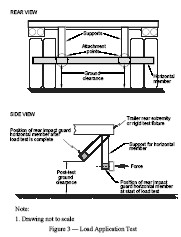
- SOR/2004-195, s. 2.
PART IV
Fuel System Integrity (Standard 301)
General
- 301
(1) Every passenger car and every multi-purpose passenger vehicle, truck and bus with a GVWR of 4 536 kg or less that is equipped with a fuel system that uses a fuel with a boiling point of 0°C or higher as a source of energy for its propulsion shall meet the requirements of Technical Standards Document No. 301, Fuel System Integrity, as amended from time to time (hereinafter referred to as TSD 301).
(2) A school bus with a GVWR of more than 4 536 kg that is equipped with a fuel system that uses a fuel with a boiling point of 0°C or higher as a source of energy for its propulsion shall meet the requirements of TSD 301.
Technical Standards Document No. 301
(3) Instead of being tested in accordance with paragraphs S6.2(a) and S6.3(a) of TSD 301, a vehicle referred to in subsection (1) may, at the option of the manufacturer, be tested in accordance with paragraphs S6.2(b) and S6.3(b) of TSD 301 before September 1, 2009.
(4) For the purposes of paragraph S7.1.6(c) of TSD 301, the unsecured mass at each designated seating position shall be 55 kg.
Expiry Date
(5) This section expires on February 28, 2009.
- SOR/80-158, s. 1; SOR/97-421, s. 17; SOR/2001-152, s. 2; SOR/2004-89, s. 1; SOR/2006-94, s. 4(E).
LPG Fuel System Integrity (Standard 301.1)
- 301.1
(1) Subject to subsections (3) and (3.1), a vehicle that is equipped with a fuel system that uses LPG as a source of energy for its propulsion shall meet the requirements of subsection (2) when tested in accordance with Test Method 301.1 — LPG Fuel System Integrity (February 28, 2004),
(a) in the case of a vehicle with a GVWR of 4 536 kg or less,
(i) by the vehicle impacting a fixed collision barrier that is at any angle of up to 30° in either direction to the perpendicular to the vehicle’s line of travel while the vehicle is travelling longitudinally forward at any speed up to and including 48 km/h,
(ii) by a collision barrier travelling at 48 km/h impacting the vehicle from the rear, and
(iii) by a collision barrier travelling at 32 km/h impacting the vehicle laterally on either side; and
(b) in the case of a vehicle with a GVWR of more than 4 536 kg, by a moving contoured barrier assembly travelling at any speed up to and including 48 km/h impacting the vehicle at any point and any angle.
(1.1) Instead of being tested in accordance with subparagraph (1)(a)(ii), a vehicle referred to in subsection (1) may be tested in accordance with paragraph S6.2(b) of TSD 301, except the fuel spillage requirements, under the applicable conditions set out in sections 3.2 to 3.4 of Test Method 301.1 – LPG Fuel System Integrity (February 28, 2004) and paragraph S7.3(b) of TSD 301.
(1.2) Instead of being tested in accordance with subparagraph (1)(a)(iii), a vehicle referred to in subsection (1) may be tested in accordance with paragraph S6.3(b) of TSD 301, except the fuel spillage requirements, under the applicable conditions set out in sections 3.2 to 3.4 of Test Method 301.1 – LPG Fuel System Integrity (February 28, 2004) and paragraph S7.2(b) of TSD 301.
(1.3) Subsections (1.1) and (1.2) expire on the day that TSD 301 expires.
(2) When a vehicle is tested in accordance with subsection (1), (1.1) or (1.2),
(a) fuel spillage from the fuel system after each impact from the moment of the impact until one-half hour after motion of the vehicle ceases shall not exceed 142 g;
(b) the temperature-corrected pressure in the high-pressure portion of the fuel system shall not decrease to less than 95 per cent of the initial system pressure during the one-half hour period after motion of the vehicle ceases; and
(c) the fuel container shall remain attached to the vehicle at a minimum of one attachment point.
(3) Instead of complying with subsections (1) and (2), a vehicle, other than a school bus, that is equipped with a fuel system that uses LPG as a source of energy for its propulsion may comply with
(a) the version of National Standard of Canada CAN/CGA-12.2, Propane Fuel System Components for Use on Highway Vehicles, that, despite any statement to the contrary in that Standard, is in effect 24 months before the date of the last manufacturing operation performed by the manufacturer who installed the fuel system, as shown on the manufacturer’s information label, or the date of manufacture of the completed vehicle, as shown on the compliance label, or a more recent version of that Standard; and
(b) section 4, Installation of Propane Fuel Systems and Tanks on Highway Vehicles, of the version of National Standard of Canada CAN/CGA-B149.5, Installation Code for Propane Fuel Systems and Tanks on Highway Vehicles, that is in effect 24 months before the date of the last manufacturing operation performed by the manufacturer who installed the fuel system, as shown on the manufacturer’s information label, or the date of manufacture of the completed vehicle, as shown on the compliance label, or a more recent version of that Standard, except that the following requirements do not apply:
(i) any requirement to obtain an approval from an authority having jurisdiction or an inspection authority of a province or territory, and
(ii) any requirement for the inspection or requalification of a fuel system or tank after the main assembly of the vehicle has been completed.
(3.1) A three-wheeled vehicle that is equipped with a fuel system that uses LPG as a source of energy for its propulsion shall comply with the standards referred to in subsection (3).
(4) A manufacturer of a vehicle that is equipped with a fuel system that uses LPG as a source of energy for its propulsion shall provide to the Minister, on request, information respecting the version of the standard referred to in subsection (3) with which the vehicle complies.
(5) [Repealed, SOR/2004-89, s. 2]
- SOR/82-754, s. 3; SOR/97-421, s. 17; SOR/2001-152, s. 2; SOR/2002-55, s. 18; SOR/2003-272, s. 29; SOR/2004-89, s. 2.
CNG Fuel System Integrity (Standard 301.2)
- 301.2
(1) Subject to subsections (3) and (3.1), a vehicle that is equipped with a fuel system that uses CNG as a source of energy for its propulsion shall meet the requirements of subsection (2) when tested in accordance with Test Method 301.2 — CNG Fuel System Integrity (February 28, 2004),
(a) in the case of a vehicle with a GVWR of 4 536 kg or less,
(i) by the vehicle impacting a fixed collision barrier that is at any angle of up to 30° in either direction to the perpendicular to the vehicle’s line of travel while the vehicle is travelling longitudinally forward at any speed up to and including 48 km/h,
(ii) by a collision barrier travelling at 48 km/h impacting the vehicle from the rear, and
(iii) by a collision barrier travelling at 32 km/h impacting the vehicle laterally on either side; and
(b) in the case of a vehicle with a GVWR of more than 4 536 kg, by a moving contoured barrier assembly travelling at any speed up to and including 48 km/h impacting the vehicle at any point and any angle.
(1.1) Instead of being tested in accordance with subparagraph (1)(a)(ii), a vehicle referred to in subsection (1) may be tested in accordance with paragraph S6.2(b) of TSD 301, except for the fuel spillage requirements, under the applicable conditions set out in sections 3.2 to 3.4 of Test Method 301.2 — CNG Fuel System Integrity (February 28, 2004) and paragraph S7.3(b) of TSD 301.
(1.2) Instead of being tested in accordance with subparagraph (1)(a)(iii), a vehicle referred to in subsection (1) may be tested in accordance with paragraph S6.3(b) of TSD 301, except for the fuel spillage requirements, under the applicable conditions set out in sections 3.2 to 3.4 of Test Method 301.2 — CNG Fuel System Integrity (February 28, 2004) and paragraph S7.2(b) of TSD 301.
(1.3) Subsections (1.1) and (1.2) expire on the day that TSD 301 expires.
(2) When a vehicle is tested in accordance with subsection (1), (1.1) or (1.2),
(a) the fuel container shall remain attached to the vehicle at a minimum of one attachment point; and
(b) when the pressure in the high-pressure portion of the fuel system is the greater of the maximum operating pressure and 20 680 kPa, this pressure shall not decrease during the 60-minute period after each impact by more than the greater of
(i) 1 062 kPa, and
(ii) the product, expressed in kPa, obtained using the following formula:
895 (T/VFS)
where
- T
- is the ambient temperature of the test gas in degrees Kelvin, and
- VFS
- is the volume of the high-pressure portion of the fuel system in litres.
(3) Instead of complying with subsection (1), a vehicle, other than a school bus, that is equipped with a fuel system that uses CNG as a source of energy for its propulsion may comply with section 4 of the version of Canadian Standards Association Standard CSA B109, Natural Gas for Vehicles Installation Code, that is in effect 24 months before the date of the last manufacturing operation performed by the manufacturer who installed the fuel system, as shown on the manufacturer’s information label, or the date of manufacture of the completed vehicle, as shown on the compliance label, or a more recent version of that Standard, except that the following requirements do not apply:
(a) any requirement to obtain an approval from, or to act under the supervision of, an authority having jurisdiction or the boiler and pressure vessel inspection authority of a province or territory; and
(b) any requirement respecting inspection, service or repair after the main assembly of the vehicle has been completed.
(3.1) A three-wheeled vehicle that is equipped with a fuel system that uses CNG as a source of energy for its propulsion shall comply with the standard referred to in subsection (3).
(4) Only a CNG cylinder that is marked in accordance with the marking requirements in one of the following standards to indicate that the cylinder complies with that standard may be installed on a vehicle that is equipped with a fuel system that uses CNG as a source of energy for its propulsion:
(a) the version of Canadian Standards Association Standard CSA B51, Part 2, High-Pressure Cylinders for the Onboard Storage of Natural Gas as a Fuel for Automotive Vehicles, that is in effect 24 months before the date of the last manufacturing operation performed by the manufacturer who installed the fuel system, as shown on the manufacturer’s information label, or the date of manufacture of the completed vehicle, as shown on the compliance label, or a more recent version of that Standard; or
(b) the version of American National Standard ANSI/AGA - NGV2, Basic Requirements for Compressed Natural Gas Vehicle (NGV) Fuel Containers, that is in effect 24 months before the date of the last manufacturing operation performed by the manufacturer who installed the fuel system, as shown on the manufacturer’s information label, or the date of manufacture of the completed vehicle, as shown on the compliance label, or a more recent version of that Standard.
(5) A manufacturer of a vehicle that is equipped with a fuel system that uses CNG as a source of energy for its propulsion shall provide to the Minister, on request, information respecting the version of the standards referred to in subsections (3) and (4) with which the vehicle complies.
(6) [Repealed, SOR/2004-89, s. 3]
- SOR/82-754, s. 3; SOR/95-77, s. 1; SOR/2001-152, s. 2; SOR/2002-55, s. 19; SOR/2003-272, s. 30; SOR/2004-89, s. 3; SOR/2005-342, s. 5.
Fuel System Integrity for Three-wheeled Vehicles and Motorcycles (Standard 301.3)
- 301.3
(1) A three-wheeled vehicle that is equipped with a fuel system that uses a fuel with a boiling point of 0°C or higher as a source of energy for its propulsion shall meet the requirements of SAE Recommended Practice J288, Snowmobile Fuel Tanks (revised version of November 1983), except that section 1 of that Practice does not apply.
(2) For the purposes of this section,
(a) the word “should” in sections 3.2, 3.3 and 4.3 and in the footnote on page 5 of SAE Recommended Practice J288 shall be interpreted as expressing an obligation;
(b) the words “snowmobile fuel” in sections 3.2, 4.3 and 4.5 of SAE Recommended Practice J288 shall be read as “unleaded gasoline”; and
(c) the word “snowmobile” in sections 4.3 and 4.5 of SAE Recommended Practice J288 shall be read as “vehicle”.
(3) Subject to subsection (5), a motorcycle that is equipped with a fuel system that uses a fuel with a boiling point of 0°C or higher as a source of energy for its propulsion shall meet the requirements of SAE Recommended Practice J1241, Fuel and Lubricant Tanks for Motorcycles (revised version of November 1999), except that section 1 of that Practice does not apply.
(4) For the purposes of this section,
(a) the words “rated fuel capacity” in SAE Recommended Practice J1241 shall have the same meaning as “vehicle fuel tank capacity” as defined in subsection 2(1) of these Regulations; and
(b) the words “significant effect” in sections 5.2.3 and 5.3.3 of SAE Recommended Practice J1241 shall be read as “any effect resulting in the cracking or leaking of the tank”.
(5) Instead of complying with subsection (3), a motorcycle that is equipped with a fuel system that uses a fuel with a boiling point of 0°C or higher as a source of energy for its propulsion may meet the requirements of the following parts of Chapter 6 of Directive 97/24/EC of the European Parliament and of the Council of June 17, 1997 on certain components and characteristics of two or three-wheel motor vehicles, as amended from time to time,
(a) Annex I, except that section 1.0 does not apply; and
(b) Appendix 1 to Annex I, except that sections 2.2 and 4 of that Appendix do not apply.
(6) For the purposes of this section, the words “rated capacity” and “nominal capacity” in Annex I and Appendix 1 to Annex I of Chapter 6 of Directive 97/24/EC of the European Parliament and of the Council of June 17, 1997 on certain components and characteristics of two or three-wheel motor vehicles shall have the same meaning as “vehicle fuel tank capacity” as defined in subsection 2(1) of these Regulations.
(7) Motorcycles that are manufactured before September 1, 2004 need not comply with this section.
- SOR/2003-272, s. 31.
Flammability
- 302
(1) Subject to subsections (4) and (5), the portion of every article described in subsection (2) that is within 13 mm (½ inch) of the occupant compartment air space, shall, when tested in the manner set out in subsection (3) in accordance with Motor Vehicle Test Method 302, Flammability, (January 9th, 1978), not burn or transmit a flame front across its surface, at a rate of more than 101.6 mm (4 inches) per minute.
(2) For the purposes of subsection (1), the articles described in this subsection are:
(a) seat cushions;
(b) seat backs;
(c) seat belts;
(d) headlining;
(e) convertible tops;
(f) arm rests;
(g) trim panels including door, front, rear and side panels;
(h) compartment shelves;
(i) head restraints;
(j) floor coverings;
(k) sun visors;
(l) curtains;
(m) shades;
(n) wheel housing covers;
(o) engine compartment covers;
(p) mattress covers; and
(q) any other materials that are designed to absorb energy on contact by occupants in the event of a crash, including padding and crash-deployed elements.
(3) The portion described in subsection (1) of every article described in subsection (2) shall be tested as follows:
(a) where the material of the portion of the article does not adhere to another material at every point of contact, it shall be tested separately; and
(b) where the material of the portion of the article adheres to another material at every point of contact, it shall be tested as a composite with the other material.
(4) The requirement of subsection (1) concerning transmission of a flame front shall not apply to a surface created by the cutting of a test specimen for purposes of testing pursuant to that subsection.
(5) Where a material stops burning before it has burned for sixty seconds from the start of timing and has not burned more than 50.8 mm (2 inches) from the point where the timing was started, it shall be deemed to comply with subsection (1).
- SOR/78-525, s. 2; SOR/79-262, s. 1(F).
Electrolyte Spillage and Electrical Shock Protection (Standard 305)
- 305
(1) Every passenger car, and every multi-purpose passenger vehicle, truck and bus with a GVWR of 4 536 kg or less, that uses more than 48 nominal volts of electricity as propulsion power and that has an attainable speed in 1.6 km of more than 40 km/h on a paved level surface shall conform to Technical Standards Document No. 305, Electrolyte Spillage and Electrical Shock Protection, as amended from time to time.
(1.1) Every three-wheeled vehicle that uses more than 48 volts of electricity as propulsion power and that has an attainable speed in 1.6 km of more than 40 km/h on a paved level surface shall comply with the requirements of Technical Standards Document No. 305, Electrolyte Spillage and Electrical Shock Protection, except sections S6.2, S6.3, S.7.4 and S7.5, as amended from time to time (hereinafter referred to as TSD No. 305).
(1.2) Instead of complying with section S7.2.3 of TSD No. 305, a three-wheeled vehicle, including test devices and instrumentation, shall be loaded to its unloaded vehicle weight, except that the vehicle fuel tank shall be filled to not less than 90 per cent and not more than 95 per cent of the vehicle fuel tank capacity.
(1.3) Instead of being tested in accordance with section S6.2 of TSD 305, a vehicle referred to in subsection (1) may be tested in accordance with section S6.2(b) of TSD 301, except the fuel spillage requirements, under the applicable conditions set out in section S7.3(b) of TSD 301.
(1.4) A vehicle tested in accordance with subsection (1.3) shall meet the requirements of sections S5.1, S5.2 and S5.3 of TSD 305.
(2) This section expires on January 1, 2010.
- SOR/2001-486, s. 2; SOR/2003-272, s. 32; SOR/2004-89, s. 4; SOR/2004-50, s. 5; SOR/2005-42, ss. 9, 10; SOR/2006-94, s. 4(E).
Low-speed Vehicles (Standard 500)
- 500
(1) Every low-speed vehicle shall conform to the requirements of Technical Standards Document No. 500, Low-speed Vehicles, as amended from time to time (hereinafter referred to as TSD 500).
(2) Despite section S5(9) of TSD 500, the vehicle identification number shall conform to section 115 of this Schedule.
(3) Despite section S5(10) of TSD 500, a Type 1 or Type 2 seat belt assembly shall conform to section 209 of this Schedule.
(4) This section expires on January 1, 2010.
- SOR/2000-304, s. 6; SOR/2005-42, ss. 11, 12.
Vehicle Stability
- 505
(1) Subject to subsection (2), the height of the centre of mass, shown in Figure 1, of a motor tricycle or a three-wheeled vehicle shall not exceed one and a half times the horizontal distance from the centre of mass to the nearest roll axis, shown in Figure 2.
(2) Subsection (1) does not apply to a motor tricycle designed in such a way that it leans during a turning manoeuvre in the same direction as the turn.
(3) The total weight of a motor tricycle or three-wheeled vehicle on all its front wheels, as measured at the tire-ground interfaces, shall be not less than 25 per cent and not greater than 70 per cent of the loaded weight of that vehicle.
(4) The loaded weight of a motor tricycle or three-wheeled vehicle and the location of its centre of mass shall be determined under the following conditions:
(a) the fuel tank is filled to any level from 90 to 95 per cent of the vehicle fuel tank capacity;
(b) a 50th percentile adult male anthropomorphic test device or an equivalent mass is located at every front outboard designated seating position but, if an equivalent mass is used, its centre of mass shall coincide, within 12 mm in the vertical dimension and 12 mm in the horizontal dimension, with a point 6 mm below the position of the H-point as determined by using the equipment and procedures specified in SAE J826 (June 1992), except that the length of the lower leg and thigh segments of the H-point machine shall be adjusted to 414 mm and 401 mm, respectively, instead of the 50th percentile values specified in Table 1 of SAE J826; and
(c) adjustable seats are placed in the adjustment position that is midway between the forward-most and rearmost positions and, if separately adjustable in a vertical direction, shall be at the lowest position but, if an adjustment position does not exist midway between the forward-most and rearmost positions, the closest adjustment position to the rear of the midpoint shall be used.
(5) For a motor tricycle or three-wheeled vehicle with one wheel at the front and two wheels at the rear, the horizontal distance from the centre of mass to the nearest roll axis, shown in Figure 2, shall be determined using the equation
d = L sin (arctan (t / 2W))
where
- d
- is the horizontal distance from the centre of mass to the nearest roll axis;
- L
- is the longitudinal distance between the centre of mass and the centre of the front axle;
- t
- is the width of the wheel track of the rear axle; and
- W
- is the wheelbase.
(6) For a motor tricycle or three-wheeled vehicle with two wheels at the front and one wheel at the rear, the horizontal distance from the centre of mass to the nearest roll axis, shown in Figure 2, shall be determined using the equation
d = (W – L) sin (arctan (t / 2W ))
where
- d
- is the horizontal distance from the centre of mass to the nearest roll axis;
- W
- is the wheelbase;
- L
- is the longitudinal distance between the centre of mass and the centre of the front axle; and
- t
- is the width of the wheel track of the front axle.
(7) Motor tricycles manufactured before September 1, 2004 need not comply with this section.
FIGURE 1 — SIDE VIEW
GRAPHIC IS NOT DISPLAYED, SEE SOR/2003-272, S. 33
FIGURE 2 — TOP VIEW
GRAPHIC IS NOT DISPLAYED, SEE SOR/2003-272, S. 33
- SOR/2003-272, s. 33.
Axles
- 901
(1) No axle, axle assembly or wheel, tire, suspension or other hardware of an axle assembly commonly referred to as running gear that is designed and manufactured exclusively for use on a mobile home or other vehicle that is not of a class prescribed by the Regulations shall be fitted to a trailer.
(2) The gross axle weight rating for each axle with which a trailer is equipped shall not
(a) in the case of a vehicle equipped with demountable rims and spoke wheels, exceed the rated load carrying capacity of
(i) the suspension springs,
(ii) the axle,
(iii) the spoke wheels,
(iv) the demountable rims, or
(v) the tires; and
(b) in the case of a vehicle equipped with disc wheels and hubs, exceed the rated load-carrying capacity of
(i) the suspension springs,
(ii) the axle,
(iii) the hubs,
(iv) the disc wheels, or
(v) the tires.
(3) The rated load carrying capacity referred to in paragraphs 2(a) and (b) for suspension springs, axles, hubs, disc wheels, spoke wheels, demountable rims or tires shall
(a) be measured at the tire-ground interface; and
(b) except in the case of heavy hauler trailers, be the continuous service ratings supplied by the respective manufacturers of the suspension springs, axles, hubs, disc wheels, spoke wheels, demountable rims or tires.
- SOR/79-940, s. 10; SOR/97-421, s. 14(E).
American Specifications Vehicle Standards[SOR/91-425, s. 3; SOR/92-173, s. 5]
902 [Repealed, SOR/95-147, s. 11]
C-dolly Specifications
- 903
(1) Every C-dolly shall be equipped with
(a) an automotive-type or a turntable-type self-steering mechanism;
(b) a means to return the wheels to within one degree of the straight-ahead position whenever any steering force applied to the wheels is removed;
(c) a device that automatically locks the steering mechanism in the straight-ahead position in the event of a failure of the means referred to in paragraph (b); and
(d) a device
(i) that includes a switch by means of which the driver can, while seated in the normal driving position in the cab of the truck towing the C-dolly, lock the steering mechanism in the straight-ahead position, or unlock it,
(ii) that locks the steering mechanism in the straight-ahead position in the event that the control for the device fails or the power supply to the device terminates, and
(iii) that includes, in both official languages, the information specified in subparagraphs (12)(b)(i) and (ii) on the switch referred in subparagraph (i) or on a label affixed near that switch.
(2) Every C-dolly shall have a GAWR of 9 100 kg.
(3) The longitudinal distance on a C-dolly, measured on the longitudinal centre-line from a point aligned with the centre of the coupling to a point aligned with the centre of the axle, shall be no greater than 2 m.
(4) Where the coupling on a C-dolly consists of a single component, that coupling shall have
(a) a static load rating of
(i) 800 kN in the longitudinal direction, and
(ii) 80 kN in the lateral direction; and
(b) a static moment rating of 76.2 kN.m about the longitudinal axis of the C-dolly.
(5) Where the coupling on a C-dolly consists of two metal eyes, the two eyes shall
(a) be separated laterally by a distance of 762 mm, ± 2 mm;
(b) be equidistant from the longitudinal centre-line of the C-dolly;
(c) have a mounting height of 900 mm, ± 10 mm, when the C-dolly is not loaded; and
(d) each have a static load rating of
(i) 400 kN in the longitudinal direction,
(ii) 100 kN in the vertical direction, and
(iii) 40 kN in the lateral direction.
(6) Where a C-dolly is tested in accordance with the Motor Vehicle Safety Test Methods, Section 903 - C-dolly (October 1, 1992), published by the Department of Transport,
(a) the axis of rotation of a turntable-type steering mechanism shall not deviate from the vertical by more than 0.5 degree;
(b) the kingpin axes of an automotive-type steering mechanism shall not deviate from the vertical by more than 0.5 degree;
(c) the steering mechanism shall keep the wheels within one degree of the straight-ahead position when the steering mechanism is subjected to
(i) a lateral force of 22 320 N that is applied to a point located 50 mm behind the centre of the tire contact patch, or
(ii) a longitudinal force of 8 930 N that is applied through the centre of one of the tires in the case of a C-dolly that is equipped with one tire on each side, and through the centre of one of the dual tires and wheel assemblies in the case of a C-dolly that is equipped with two tires on each side; and
(d) the steering mechanism shall not permit the wheels to move beyond one degree from the straight-ahead position unless the steering mechanism is subjected to a force exceeding the force referred to in subparagraph (c)(i) or (ii).
(7) Where a C-dolly is equipped with a pressurized hydraulic or pneumatic system that provides the means referred to in paragraph (1)(b), the system shall
(a) be independent of the brake system of the C-dolly;
(b) be fitted with a pressure gauge that indicates
(i) the minimum pressure required to meet the requirements of paragraphs (1)(b) and (6)(c) and (d), and
(ii) the amount of pressure in the system; and
(c) not permit any adjustment of the steering force.
(8) Every C-dolly referred to in subsection (7) shall bear a label, in both official languages, that states the minimum pressure referred to in paragraph (7)(b).
(9) Every pressure gauge referred to in subsection (7) and every manual valve and switch, if any, that forms part of a system referred to in that subsection, and every label referred to in subsection (8), shall be protected from adverse weather conditions.
(10) Every C-dolly that is subjected to a torsion test conducted in accordance with the Motor Vehicle Safety Test Methods, Section 903 - C-dolly (October 1, 1992), published by the Department of Transport, shall have a torsional stiffness of at least 3 000 N.m/degree with respect to the longitudinal direction, and shall be capable of sustaining a torque of at least 45 000 N.m in either direction without incurring a residual deformation that exceeds 0.5 degree.
(11) Where a C-dolly is equipped with a device that is intended to lock the steering mechanism automatically according to the speed of the C-dolly, that device shall
(a) lock the steering mechanism in the straight-ahead position when the C-dolly is travelling at a speed of 60 km/h and keep the steering mechanism locked when the C-dolly is travelling at a speed greater than 60 km/h; and
(b) unlock the steering mechanism when the C-dolly is travelling at a speed of 50 km/h and keep the steering mechanism unlocked when the C-dolly is travelling at a speed less than 50 km/h.
(12) Every C-dolly shall
(a) have a flat surface that is horizontal when the C-dolly is not loaded and when the centre of the coupling on the C-dolly is held at the mounting height in accordance with the manufacturer’s design; and
(b) bear a label, in both official languages, that states
(i) that the steering mechanism should be locked when the C-dolly is travelling at a speed of 60 km/h or more on any slippery or unpaved road, and that the steering mechanism should be unlocked when the C-dolly is travelling at a speed of 50 km/h or less, and
(ii) that the C-dolly shall not be attached to a straight truck.
(13) The flat surface referred to in paragraph (12)(a) shall be
(a) at least 30 cm in length, measured longitudinally;
(b) at least 5 cm in width, measured laterally;
(c) accessible from both sides of the C-dolly; and
(d) within 50 cm of the coupling of the C-dolly.
- SOR/93-146, s. 4.
C-dolly Hitch Requirements
- 904
(1) Every trailer that is designed to tow a C-dolly shall be equipped with a coupling to connect the trailer to the C-dolly.
(2) Where a coupling referred to in subsection (1) consists of a single component, the coupling shall have
(a) a static load rating of
(i) 800 kN in the longitudinal direction, and
(ii) 80 kN in the lateral direction; and
(b) a static moment rating of 76.2 kN.m about the longitudinal axis of the C-dolly.
(3) Where a coupling referred to in subsection (1) consists of two separate hitches, the hitches shall
(a) be separated laterally by a distance of 762 mm, ± 2 mm;
(b) be equidistant from the longitudinal centre-line of the trailer;
(c) have a mounting height of 900 mm, ± 10 mm, when the trailer is not loaded; and
(d) each have a static load rating of
(i) 400 kN in the longitudinal direction,
(ii) 100 kN in the vertical direction, and
(iii) 40 kN in the lateral direction.
- SOR/93-146, s. 4.
Trailer Cargo Anchoring Devices (Standard 905)
- 905
(1) The definitions in this subsection apply in this section.
- bulkhead
bulkhead means a fixed or removable structure installed across the width of a trailer to restrict the movement of cargo during transport. (cloison)
- cargo anchoring device
cargo anchoring device means a fitting or attachment point on a trailer, other than a bulkhead or rub rail, to which a tie-down assembly is attached. (dispositif d’ancrage des chargements)
- rub rail
rub rail means a protector strip extending horizontally along the sides of a trailer intended to provide protection from scuffing. (bourrelet de protection)
(2) This section applies to every trailer that is designed to carry cargo, with a GVWR of 10 000 kg or more, a load-carrying mainframe and loading deck and no permanent sides or roof, such as a flatbed trailer, heavy hauler trailer, industrial trailer, lowbed trailer or drop-centre trailer.
(3) Every trailer shall, for the purpose of affixing cargo, be equipped with at least the number of cargo anchoring devices determined in accordance with the formula
N = M / 2 000 kg
where
- N
- is the minimum number of cargo anchoring devices, rounded up to the next even whole number; and
- M
- is the cargo carrying capacity of the trailer, calculated as the difference between its gross vehicle weight rating and its curb mass, expressed in kilograms.
(4) The minimum number of cargo anchoring devices determined in accordance with subsection (3) shall, when tested in accordance with Test Method 905-Trailer Cargo Anchoring Devices (August 1998), withstand a force of at least 67 000 N applied in an upward vertical direction.
- SOR/98-595, s. 2.
Snowmobile Trailers (Standard 906)
906 Every snowmobile trailer shall be equipped with
(a) one or more tie-down cross bars located in such a manner as to be capable of clamping the skis of as many snowmobiles as the trailer is capable of carrying; and
(b) tie-down points to which each snowmobile can be secured by ropes or straps and that are of sufficient strength to withstand a force of 2 224.11 N (500 pounds) applied separately from any direction to each tie-down point.
- SOR/2003-359, s. 4
SCHEDULE V
SCHEDULE V.1(Section 5)
Noise Emissions (Standard 1106)
Interpretation
1 The definitions in this section apply in this Schedule and in the documents referred to in this Schedule.
- dBA
dBA means the A-weighted sound level in decibels, measured using a sound level meter or a sound data acquisition system referred to in Appendix A of Test Method 1106 — Noise Emission Tests (August 2005) that uses the values set out in Table 1 of that Appendix. (dBA)
- decibel
decibel or dB means 20 times the logarithm to the base 10 of the ratio of the measured sound pressure relative to a reference sound pressure of 20 µPa. (décibel ou dB)
- rated engine speed
rated engine speed or maximum rated engine speed means the rotational speed of an engine in revolutions per minute (RPM) at which the maximum horsepower of the engine is attained. (régime maximal nominal, rated engine speed ou maximum rated engine speed)
- sound level
sound level means the root-mean-square of the values measured in dBA that are recorded during testing conducted pursuant to this section. (niveau sonore)
- SOR/2005-342, s. 6.
Exterior Sound Level
2 Every vehicle, other than a motorcycle or a vehicle referred to in section 4, shall be so constructed that
(a) where tested in accordance with Annex 3 to ECE Regulation No. 51, Uniform Provisions concerning the Approval of Motor Vehicles Having at Least Four Wheels with regard to Their Noise Emissions, dated March 11, 1996, excluding the requirements of paragraph 3.2 of that Annex, the vehicle conforms to section 6 of that Regulation; or
(b) where tested in accordance with
(i) section 3 of Test Method 1106 — Noise Emission Tests (August 2005), the exterior sound level does not exceed 83 dBA when a value of 2 dBA is subtracted from the highest average sound level recorded during the test, in the case of a bus with a GVWR of more than 4 536 kg (10,000 lb.),
(ii) SAE Recommended Practice J986, Sound Level for Passenger Cars and Light Trucks (August 1994), or SAE Standard J1470, Measurement of Noise Emitted by Accelerating Highway Vehicles (March 1992), the exterior sound level does not exceed 83 dBA when a value of 2 dBA is subtracted from the highest average sound level recorded during the test, in the case of a heavy-duty vehicle with a GVWR of 4 536 kg (10,000 lb.) or less, and
(iii) SAE Recommended Practice J986, Sound Level for Passenger Cars and Light Trucks (August 1994), or SAE Standard J1470, Measurement of Noise Emitted by Accelerating Highway Vehicles (March 1992), the exterior sound level does not exceed 80 dBA when a value of 2 dBA is subtracted from the highest average sound level recorded during the test, in the case of a light-duty vehicle.
- SOR/2005-342, s. 6.
3 Every motorcycle shall be so constructed that
(a) where tested in accordance with Annex 3 to ECE Regulation No. 41, Uniform Provisions concerning the Approval of Motor Cycles with regard to Noise, dated January 19, 1981, as amended September 14, 1984, excluding the requirements of paragraph 3.2 of that Annex, the exterior sound level does not exceed
(i) 77 dBA, in the case of a motorcycle with an engine displacement not exceeding 80 cm3,
(ii) 80 dBA, in the case of a motorcycle with an engine displacement exceeding 80 cm3 and not exceeding 175 cm3, and
(iii) 82 dBA, in the case of a motorcycle with an engine displacement exceeding 175 cm3; or
(b) where tested in accordance with
(i) Appendix I-2 to subparts D and E, part 205, chapter I, title 40 of the United States Code of Federal Regulations, as amended by Vol. 45, No. 252 of the Federal Register of the United States published on December 31, 1980, at pages 86727 and 86728, the exterior sound level does not exceed 70 dBA, in the case of a motorcycle with an engine displacement not exceeding 50 cm3 and a maximum attainable speed of 48 km/h on a level paved surface, and
(ii) Appendix I-1 to subparts D and E, part 205, chapter I, title 40 of the United States Code of Federal Regulations, as amended by Vol. 45, No. 252 of the Federal Register of the United States published on December 31, 1980, at pages 86726 and 86727, the exterior sound level does not exceed 80 dBA, in any other case.
4 Every truck or incomplete vehicle fitted with a cab, with a GVWR of more than 4 536 kg (10,000 lb.) shall be so constructed that
(a) where the vehicle is tested in accordance with Annex 3 to ECE Regulation No. 51, Uniform Provisions concerning the Approval of Motor Vehicles Having at Least Four Wheels with regard to Their Noise Emissions, dated March 11, 1996, excluding the requirements of paragraph 3.2 of that Annex, the exterior sound level does not exceed
(i) 81 dBA, in the case of a heavy-duty truck with an engine that produces less than 75 kW,
(ii) 83 dBA, in the case of a heavy-duty truck with an engine that produces at least 75 kW but less than 150 kW, and
(iii) 84 dBA, in the case of a heavy-duty truck with an engine that produces 150 kW or more; or
(b) where the vehicle is tested in accordance with the low speed sound emission test procedures set out in section 205.54-1 of subpart B, part 205, chapter I, title 40 of the United States Code of Federal Regulations (revised as of July 1, 1995), the exterior sound level does not exceed 80 dBA.
- SOR/2002-55, s. 20.
Interior Sound Level
5 Every truck or bus with a GVWR of more than 4 536 kg (10,000 lb.) shall be so constructed that, where tested in accordance with section 4 of Test Method 1106 — Noise Emission Tests (August 2005), the interior sound level at the driver’s seating position does not exceed 90 dBA when a value of 2 dBA is subtracted from the average sound level obtained in accordance with the test.
- SOR/2005-342, s. 6
SCHEDULE VI(Section 5)
1200 [Repealed, SOR/96-360, s. 1]
Snowmobile Standards
1201 (1) Every snowmobile shall be constructed so that it conforms to the requirements set out in the following standards:
(a) the Safety Standards for Snowmobile Product Certification, SSCC/11, published by the Snowmobile Safety and Certification Committee, Inc., dated February 6, 2003, except that the following provisions do not apply:
(i) section 13, respecting vehicle identification numbers,
(ii) section 14, respecting certification markings of exhaust systems,
(iii) Figures 4, 6 and 7, respecting labelling requirements, and
(iv) subsection 12(c)(6), requiring a label stating that the use of children’s snowmobiles is prohibited on public trails; and
(b) the Detailed Standards and Testing Specifications and Procedures, SSCC/11 Supplement, published by the Snowmobile Safety and Certification Committee, Inc., dated February 6, 2003, except that the following provisions do not apply:
(i) section 3.1 of L-S-300A,
(ii) subsection 4.3.3 and section 5 of L-S-300A, respecting packing requirements,
(iii) subsection 6.2 of L-S-300A, respecting ordering information,
(iv) section 6 of 62-GP-11P, respecting packing requirements, and
(v) section 8.2 of 62-GP-11P, respecting ordering data.
(1.1) When a snowmobile is tested, instead of using the version of the approved tests set out in the Supplement referred to in paragraph (1)(b), the manufacturer may use the version of those tests that is in effect on January 1 of the calendar year in which the snowmobile is manufactured.
(1.2) For the purposes of this section, the word “snowmobile” used in the Standards and Supplement referred to in subsection (1) has the same meaning as in subsection 2(1) of these Regulations.
(2) Notwithstanding the definition Designed or Designed to referred to in section 4 of the Standards referred to in subsection (1) and for the purposes of those Standards and the Supplement referred to in that subsection, Designed and Designed to shall mean designed and constructed in such a manner so as to conform to the performance requirements of those documents under normal conditions of operation.
(3) The use of the word “should” in paragraph 10c.(4) of the Standards referred to in subsection (1) and of the word “will” in those Standards and the Supplement referred to in that subsection shall be considered to create an obligation.
(4) The reference to the Supplement referred to in subsection (1) shall be interpreted as excluding the statements that set out a recommended practice or guideline by using, for example, the auxiliary “should”.
(5) The statement required pursuant to paragraph 12c.(2) of the Standards referred to in subsection (1), the information specified on the label or plaque that must be affixed to a snowmobile pursuant to paragraph 12c.(6) of those Standards and any instructions that are provided with a snowmobile shall be provided in both official languages.
(6) Every snowmobile shall be equipped with the emergency stop switch set out in the Standards referred to in subsection (1) and headlamps that are on continuously when the engine of the snowmobile is operating.
- SOR/87-497, s. 3; SOR/87-660, s. 6; SOR/96-360, s. 2; SOR/97-532, s. 4; SOR/2000-182, s. 9; SOR/2003-359, s. 5.
Snowmobile Cutters (Standard 1202)
1202 (1) Every snowmobile cutter shall be equipped with a rigid tow bar that, when connected to a snowmobile, is
(a) rigidly connected to the cutter so as to prevent yawing movement;
(b) capable of 90 degrees of rolling movement in each direction in relation to the longitudinal vertical plane of the cutter; and
(c) capable of allowing adequate pitching movement of the cutter.
(2) Snowmobile cutters shall be equipped with the following reflex reflectors, located not more than 760 mm above the ground measured to the centre of the reflex reflectors with the cutter at curb mass:
(a) on the rear, the reflex reflectors referred to in SAE Recommended Practice J292, Snowmobile and Snowmobile Cutter Lamps, Reflective Devices and Associated Equipment (May 1995); and
(b) on each side at the mid-point of the cutter,
(i) the reflex reflectors referred to in SAE Recommended Practice J292, Snowmobile and Snowmobile Cutter Lamps, Reflective Devices and Associated Equipment (May 1995), or
(ii) reflex reflectors that have a minimum area, as projected in side elevation, of 100 cm2 and that are composed of Class 1 or 3 reflective materials, as specified in Canadian General Standards Board Standard CGSB 62-GP-11M, Marking Material, Retroreflective Enclosed Lens, Adhesive Backing (May 1978), of any colour or combination of colours set out in Table 1 of that Standard and with a reflective intensity value of Level 1 as specified in Table 2 of that Standard.
(3) The skis of a snowmobile cutter shall be capable of being clamped to a snowmobile trailer by means of a tie-down cross bar attached to the trailer and passing over or through the skis.
- SOR/2003-359, s. 6
1203. to 1206 [Repealed, SOR/87-660, s. 6]
1207. to 1209 [Repealed, SOR/2003-359, s. 7]
1210. and 1211 [Repealed, SOR/87-660, s. 8]
SCHEDULE VII(Subsections 11(2) and (6))Declaration of Importation of a Vehicle for Exhibition, Demonstration, Evaluation, Testing or Special Purposes
1 Name of the manufacturer of the vehicle:
2 Name and address of the person importing the vehicle:
3 The month and year the vehicle was manufactured:
4 The class, make, model and vehicle identification number of the vehicle:
5 The date the vehicle is presented for importation:
6 The purpose of the importation:
7 The estimated period of time the vehicle will be used on public roads:
8 Whether the vehicle will be removed from Canada or destroyed after completion of the purpose for which it is imported:
9 The date the vehicle will be removed from Canada or destroyed:
- I, the undersigned,, declare that the information set out in this
- (Authorized representative)
- declaration is true and that
(a) the vehicle is being imported into Canada solely for purposes of
(i) exhibition, demonstration, evaluation or testing, pursuant to paragraph 7(1)(a) of the Motor Vehicle Safety Act,
(ii) undergoing further manufacturing prior to export, or
(iii) conducting works or operations that require a specially designed vehicle; and
(b) the vehicle will remain in Canada for a period not longer than one year or, in the case of a vehicle being imported under paragraph 7(1)(a) of the Act, for such shorter period as the Minister specifies.Footnote *
| | |
| Signature of authorized representative | Date | |
Return to footnote *Note: Subsection 7(5) of the Motor Vehicle Safety Act prohibits a person who signs the declaration referred to in paragraph 7(1)(a) of the Act to use or dispose of a vehicle other than in accordance with the terms of the declaration.
- SOR/95-147, s. 14
- SOR/2000-182, ss. 10 to 12
SCHEDULE VIII(Paragraph 12(3)(e))Designated Customs Offices
Ontario
- 1Cornwall
- 2Fort Erie
- 3Fort Frances
- 4Lansdowne
- 5Niagara Falls (Queenston Bridge)
- 6Pidgeon River
- 7Prescott
- 8Sarnia
- 9Sault Ste. Marie
- 10Windsor-Ambassador Bridge
- 11Windsor Tunnel
Quebec
- 12Lacolle
- 13Rock Island
- 14St-Armand-Philipsburg
- 15Stanhope
New Brunswick
- 16Edmundston
- 17St. Stephen
- 18Woodstock Road
Manitoba
- 19Emerson
British Columbia
- 20Huntingdon
- 21Kingsgate
- 22Osoyoos
- 23Pacific Highway
Saskatchewan
- 24North Portal
Alberta
- 25Coutts
- SOR/95-147, s. 14
Page Details
- Date modified: