
Table of Contents
Motor Vehicle Restraint Systems and Booster Cushions Safety Regulations
SOR/98-159
Registration 1998-03-12
Motor Vehicle Restraint Systems and Booster Cushions Safety Regulations
P.C. 1998-355 1998-03-12
Whereas, pursuant to subsection 11(3) of the Motor Vehicle Safety ActFootnote a, a copy of the proposed Motor Vehicle Restraint Systems and Booster Cushions Safety Regulations, substantially in the form set out in the annexed Regulations, was published in the Canada Gazette, Part I, on July 13, 1996, and an amendment to those Regulations, substantially in the form set out in the annexed Regulations, was published in the Canada Gazette, Part I, on January 18, 1997, and a reasonable opportunity was thereby afforded to interested persons to make representations to the Minister of Transport with respect thereto;
Return to footnote aS.C. 1993, c. 16
Therefore, His Excellency the Governor General in Council, on the recommendation of the Minister of Transport, pursuant to section 5 and subsection 11(1) of the Motor Vehicle Safety Acta, hereby makes the annexed Motor Vehicle Restraint Systems and Booster Cushions Safety Regulations.
Interpretation
1 (1) The definitions in this subsection apply in these Regulations.
- Act
Act means the Motor Vehicle Safety Act. (Loi)
- booster cushion
booster cushion means a removable device for use in a vehicle for the purpose of seating in an elevated position a person whose mass is 18 kg or more, which device, together with a vehicle seat belt, is used in the restraint of the person. (coussin d’appoint)
- car bed
car bed means a restraint system for infants with special needs that is designed to restrain infants with special needs in a supine or prone position on a continuous flat surface. (lit d’auto)
- child
child means a person whose weight is not less than 9 kg and not more than 22 kg. (enfant)
- child restraint system
child restraint system means a restraint system that is designed for use, together with a vehicle seat belt, in the restraint of a child. (ensemble de retenue pour enfant)
- custom restraint system for disabled persons
custom restraint system for disabled persons means a restraint system for disabled persons that is designed for use in the restraint of a specific mobility-impaired occupant. (ensemble de retenue sur mesure pour personne handicapée)
- infant
infant means a person who is incapable of sitting erect and whose weight is less than 9 kg. (bébé)
- infant restraint system
infant restraint system means a restraint system that is designed for use, together with a vehicle seat belt, in the restraint of an infant. (ensemble de retenue pour bébé)
- infants with special needs
infants with special needs means infants born at less than 37 weeks gestation, infants whose weight at birth is less than 2.2 kg or infants with special breathing needs. (bébés qui ont des besoins spéciaux)
- lower connector system
lower connector system means a system consisting of two connectors that each fit inside a checking device that has the envelope dimensions shown in Figure 10 of Schedule 10, are attached to the lower part of a restraint system or booster cushion in a manner that does not allow for their removal without the use of tools and enable the restraint system or booster cushion to be securely attached to a lower universal anchorage system of a vehicle. (système d’attaches inférieures)
- lower universal anchorage system
lower universal anchorage system means a device, other than a vehicle seat belt, that is designed to secure the lower portion of a restraint system or booster cushion to a vehicle and that transfers loads from the restraint system or booster cushion and its occupant to the vehicle structure or seat. (dispositif universel d’ancrages d’attaches inférieurs)
- mobility-impaired occupant
mobility-impaired occupant means a person whose mass is 9 kg or more and who, for orthopaedic reasons or because of the person’s build or other physical characteristics, is unable to use a child restraint system, a booster cushion, a built-in child restraint system or a built-in booster cushion referred to in section 213.4 of Schedule IV to the Motor Vehicle Safety Regulations, or a vehicle seat belt. (occupant à mobilité réduite)
- production restraint system for disabled persons
production restraint system for disabled persons means a restraint system for disabled persons other than a custom restraint system for disabled persons. (ensemble de retenue de série pour personne handicapée)
- restraint system
restraint system means a removable device designed to be installed in a vehicle for use in the restraint of an infant, a child or a mobility-impaired occupant, but does not include booster cushions or vehicle seat belts. (ensemble de retenue)
- restraint system for disabled persons
restraint system for disabled persons means a restraint system that is designed to be placed directly on the seat of a vehicle for use, together with a vehicle seat belt, in the restraint of a mobility-impaired occupant. (ensemble de retenue pour personne handicapée)
- restraint system for infants with special needs
restraint system for infants with special needs means a restraint system that is designed or has special characteristics for use, together with a vehicle seat belt, in the restraint of infants with special needs. (ensemble de retenue pour bébés qui ont des besoins spéciaux)
- Test Method
Test Method means a document published by the Department of Transport that contains motor vehicle safety test methods under the main heading Test Method, followed by an identification number, a descriptive title and the publishing date. (Méthode d’essai)
- tether strap
tether strap means a device that is fitted with a tether strap hook and secured to the rigid structure of a restraint system or booster cushion and that transfers the load from that system or booster cushion to the user-ready tether anchorage. (courroie d’attache)
- tether strap hook
tether strap hook means a device that is used to attach a tether strap to a user-ready tether anchorage and has an interface profile shown in Figure 1 of Schedule 10 or, in the case of a device with integrated adjustment hardware, Figure 2 of Schedule 10. (crochet de la courroie d’attache)
- TSD 209
TSD 209 means Technical Standards Document No. 209, Seat Belt Assemblies, referred to in subsection 209(1) of the Motor Vehicle Safety Regulations. (DNT 209)
(2) A weight or height required to be indicated under sections 6 to 11 must be expressed in units based on the International System of Units, followed by the corresponding imperial units in parentheses.
(3) [Repealed, SOR/2008-104, s. 27]
- SOR/2000-89, s. 1
- SOR/2001-341, s. 1
- SOR/2002-206, s. 1
- SOR/2007-180, s. 23
- SOR/2008-72, s. 13(F)
- SOR/2008-104, s. 27
National Safety Mark
2 (1) For the purposes of subsection 3(2) of the Act, the Minister may authorize a company to apply the national safety mark to a restraint system or booster cushion, including any accompanying documentation or packaging.
(2) A company that intends to apply the national safety mark to a restraint system or booster cushion must apply to the Minister to obtain an authorization in the form set out in Schedule 1.
(3) Every company that applies the national safety mark to a restraint system or booster cushion must indelibly mould into or onto it, or print on a label affixed to it in a permanent manner, in a readily visible location, a drawing at least 50 mm in diameter depicting the national safety mark, as set out in Schedule 2, and showing the following information:
(a) the authorization number assigned to the company by the Minister; and
(b) the number of the standard or standards to which the restraint system or booster cushion conforms, namely,
(i) 213, in the case of a child restraint system,
(ii) 213.1, in the case of an infant restraint system,
(iii) 213.2, in the case of a booster cushion,
(iv) 213.3, in the case of a production restraint system for disabled persons, or
(v) 213.5, in the case of a restraint system for infants with special needs.
- SOR/2008-104, s. 28
Prescribed Classes of Equipment
3 Child restraint systems, infant restraint systems, booster cushions, restraint systems for disabled persons and restraint systems for infants with special needs are prescribed classes of equipment for the purposes of section 5 of the Act.
Prescribed Standards
4 (1) Every child restraint system must conform to the applicable standards set out in Schedule 3, CMVSS 213 — Child Restraint Systems.
(2) Every infant restraint system must conform to the applicable standards set out in Schedule 4, CMVSS 213.1 — Infant Restraint Systems.
(3) [Repealed, SOR/2001-341, s. 2]
(4) Every booster cushion must conform to the applicable standards set out in Schedule 5, CMVSS 213.2 — Booster Cushions.
(5) Every restraint system for disabled persons must conform to the applicable standards set out in Schedule 6, CMVSS 213.3 — Restraint Systems for Disabled Persons.
(6) Every restraint system for infants with special needs must conform to the applicable standards set out in Schedule 7, CMVSS 213.5 — Restraint Systems for Infants with Special Needs.
(7) Every restraint system that is designed to be used as more than one type of restraint system or as a restraint system and booster cushion must conform to the standards set out in Schedules 3 to 7 that are applicable to each type of restraint system or booster cushion for which it is designed to be used.
- SOR/2001-341, s. 2
Restraint System and Booster Cushion Information
National Safety Mark
5 No company shall import a restraint system, other than a custom restraint system for disabled persons, or a booster cushion unless the restraint system or booster cushion bears the national safety mark.
- SOR/2008-104, s. 29
Lower Universal Anchorage System Symbol
5.1 Every restraint system or booster cushion that is equipped with a lower connector system must bear the lower universal anchorage system symbol, illustrated in Schedule 11, on a contrasting background on or near the lower connector system in a clearly visible location that readily permits the lower connectors to be engaged and attached.
- SOR/2002-206, s. 2
Child Restraint Systems
6 Every child restraint system must have indelibly moulded into or onto it, or indelibly printed on a label affixed to it in a permanent manner, in both official languages, in a readily visible location,
(a) the name and principal place of business of the company that manufactured, imported or sold the system;
(b) the model name and number of the system;
(c) the date of manufacture of the system, in the form set out in Schedule 8;
(d) a statement that indicates
(i) the weight and height range of the children for whom the system is designed, as recommended by the manufacturer, if the system is designed as a forward-facing system for use by children, or
(ii) the weight and height range of the infants and the children for whom the system is designed, as recommended by the manufacturer, if the system is designed to be used as a rearward-facing system for infants and as a forward-facing system for children;
(e) the characteristics of vehicles in which the system is not to be used;
(f) a warning that
(i) if the system is designed to employ belts to restrain a child, the belts provided with the system are to be snugly adjusted around the child,
(ii) if the system is not designed for use at certain adjustment positions, those adjustment positions must not be used,
(iii) in the case of a forward-facing system, the system must be secured to the vehicle by means of a lower connector system if it is installed in a seating position that is equipped with a lower universal anchorage system or by means of a vehicle seat belt if it is installed in a seating position that is not equipped with a lower universal anchorage system, and by means of a tether strap, as shown in the installation instructions,
(iii.1) in the case of a rearward-facing system, the system must be secured to the vehicle by means of a lower connector system if it is installed in a seating position that is equipped with a lower universal anchorage system or by means of a vehicle seat belt if it is installed in a seating position that is not equipped with a lower universal anchorage system, and, if equipped with a tether strap, by means of the tether strap, as shown in the installation instructions,
(iv) if the system employs a fixed or movable surface to restrain a child and also requires belts, the fixed or movable surface is not sufficient to restrain the child; and
(g) an installation diagram that shows the system correctly installed
(i) in a seating position that is equipped only with a lap belt and secured to the vehicle by means of the lap belt and, if the system is equipped with a tether strap, by means of the tether strap, if the manufacturer recommends the installation of the system in such a seating position,
(ii) in a seating position that is equipped only with a continuous-loop lap and shoulder belt and secured to the vehicle by means of the belt and, if the system is equipped with a tether strap, by means of the tether strap, if the manufacturer recommends the installation of the system in such a seating position, and
(iii) in a seating position that is equipped with a lower universal anchorage system and secured to the vehicle by means of a lower connector system and, if equipped with a tether strap, by means of the tether strap.
- SOR/2001-341, s. 3
- SOR/2002-206, s. 3
Infant Restraint Systems
7 Every infant restraint system must have indelibly moulded into or onto it, or indelibly printed on a label affixed to it in a permanent manner, in both official languages, in a readily visible location,
(a) the name and principal place of business of the company that manufactured, imported or sold the system;
(b) the model name and number of the system;
(c) the date of manufacture of the system, in the form set out in Schedule 8;
(d) a statement that indicates
(i) the weight and height range of the infants for whom the system is designed, as recommended by the manufacturer, if the system is designed as a rearward-facing system for use by infants, or
(ii) the weight and height range of the infants and the children for whom the system is designed, as recommended by the manufacturer, if the system is designed to be used as a rearward-facing system for infants and as a forward-facing system for children;
(e) the characteristics of vehicles in which the system is not to be used;
(f) a warning that
(i) the system is for use only in a forward-facing seat equipped with a lower universal anchorage system or with a vehicle seat belt,
(ii) the system is to be in a rearward-facing position when it is used for an infant,
(iii) the system must be secured to the vehicle by means of a lower connector system if it is installed in a seating position that is equipped with a lower universal anchorage system or by means of a vehicle seat belt if it is installed in a seating position that is not equipped with a lower universal anchorage system, and, if equipped with a tether strap, by means of the tether strap, and
(iv) the belts provided with the system are to be snugly adjusted around the infant;
(g) a statement, on a red, yellow or orange background, placed on the side of the system that will face the right front passenger door when the system is facing rearward or in or adjacent to the area where the infant's head would rest and visible to a person installing the system, warning that the restraint system must not be installed in the front seat of a vehicle equipped with a passenger-side frontal air bag; and
(h) an installation diagram that shows the system correctly installed
(i) in a seating position that is equipped only with a lap belt and secured to the vehicle by means of the lap belt and, if the system is equipped with a tether strap, by means of the tether strap, if the manufacturer recommends the installation of the system in such a seating position,
(ii) in a seating position that is equipped only with a continuous-loop lap and shoulder belt and secured to the vehicle by means of the belt and, if the system is equipped with a tether strap, by means of the tether strap, if the manufacturer recommends the installation of the system in such a seating position, and
(iii) in a seating position that is equipped with a lower universal anchorage system and secured to the vehicle by means of a lower connector system and, if equipped with a tether strap, by means of the tether strap.
- SOR/2001-341, s. 4
- SOR/2002-206, s. 4
- SOR/2008-104, s. 30
Booster Cushions
8 Every booster cushion must have indelibly moulded into or onto it, or indelibly printed on a label affixed to it in a permanent manner, in both official languages, in a readily visible location,
(a) the name and principal place of business of the company that manufactured, imported or sold the booster cushion;
(b) the model name and number of the booster cushion;
(c) the date of manufacture of the booster cushion, in the form set out in Schedule 8;
(d) a statement that indicates that the booster cushion is for use by persons whose mass is at least 18 kg (40 pounds) and who are at least the minimum height recommended by the manufacturer;
(e) in the case of a booster cushion that is equipped with a lower connector system, a statement that indicates that, even when unoccupied, the booster cushion must be secured to the vehicle by means of that system if the booster cushion is installed in a seating position that is equipped with a lower universal anchorage system or by means of a vehicle seat belt if it is installed in a seating position that is not equipped with a lower universal anchorage system, and, if equipped with a tether strap, by means of the tether strap;
(e.1) in the case of a booster cushion that is not equipped with a lower connector system, a statement that indicates that, even when unoccupied, the booster cushion must be secured to the vehicle by means of a vehicle seat belt and, if equipped with a tether strap, by means of the tether strap;
(f) an installation diagram that shows the booster cushion correctly installed
(i) in a seating position that is equipped only with a lap belt and secured to the vehicle by means of the lap belt and, if the booster cushion is equipped with a tether strap, by means of the tether strap, if the manufacturer recommends the installation of the booster cushion in such a seating position,
(ii) in a seating position that is equipped only with a continuous-loop lap and shoulder belt and secured to the vehicle by means of the belt and, if the booster cushion is equipped with a tether strap, by means of the tether strap, if the manufacturer recommends the installation of the booster cushion in such a seating position, and
(iii) if equipped with a lower connector system, in a seating position that is equipped with a lower universal anchorage system and secured to the vehicle by means of that system and, if equipped with a tether strap, by means of the tether strap.
- SOR/2001-341, s. 5
- SOR/2002-206, s. 5
- SOR/2008-104, s. 31
Production Restraint Systems for Disabled Persons
9 Every production restraint system for disabled persons must have indelibly moulded into or onto it, or indelibly printed on a label affixed to it in a permanent manner, in both official languages, in a readily visible location,
(a) the name and principal place of business of the company that manufactured, imported or sold the system;
(b) the model name and number of the system;
(c) the date of manufacture of the system, in the form set out in Schedule 8;
(d) a statement that the system conforms to the prescribed standards applicable at the time of manufacture;
(e) a statement that indicates that the system is designed for use by mobility-impaired occupants and the weight and height range of the occupants for whom the system is designed, as recommended by the manufacturer;
(f) the characteristics of vehicles in which the system is not to be used;
(g) a warning that
(i) if the system is designed to employ belts to restrain a mobility-impaired occupant, the belts provided with the system are to be snugly adjusted around the occupant,
(ii) if the system is not designed for use at certain adjustment positions or for use with trays or tables or certain webbing assemblies, those adjustment positions, trays, tables or webbing assemblies must not be used,
(iii) in the case of a system that is equipped with a lower connector system, the system must be secured to the vehicle by means of the lower connector system if it is installed in a seating position that is equipped with a lower universal anchorage system or by means of a vehicle seat belt if it is installed in a seating position that is not equipped with a lower universal anchorage system, and, if equipped with a tether strap, by means of the tether strap, as shown in the installation instructions,
(iii.1) in the case of a system that is not equipped with a lower connector system, the system must be secured to the vehicle by means of a vehicle seat belt and, if equipped with a tether strap, by means of the tether strap, as shown in the installation instructions,
(iv) if the system employs a fixed or movable surface to restrain a mobility-impaired occupant but also requires harness straps, the fixed or movable surface is not sufficient to restrain the occupant; and
(h) an installation diagram that shows the system correctly installed
(i) in a seating position that is equipped only with a lap belt and secured to the vehicle by means of the lap belt and, if the system is equipped with a tether strap, by means of the tether strap, if the manufacturer recommends the installation of the system in such a seating position,
(ii) in a seating position that is equipped only with a continuous-loop lap and shoulder belt and secured to the vehicle by means of the belt and, if the system is equipped with a tether strap, by means of the tether strap, if the manufacturer recommends the installation of the system in such a seating position, and
(iii) if equipped with a lower connector system, in a seating position that is equipped with a lower universal anchorage system and secured to the vehicle by means of that system and, if equipped with a tether strap, by means of the tether strap.
- SOR/2001-341, s. 6
- SOR/2002-206, s. 6
Custom Restraint Systems for Disabled Persons
10 Every custom restraint system for disabled persons must be accompanied by a document, in both official languages, that contains the following information:
(a) a statement that the system is to be used only by the mobility-impaired occupant for whom it was designed;
(b) the name and principal place of business of the company that manufactured, imported or sold the system;
(c) the date of manufacture of the system, in the form set out in Schedule 8;
(d) a statement that the system conforms to the prescribed standards applicable at the time of manufacture;
(e) if the system is not designed for use at certain adjustment positions or for use with trays or tables or certain webbing assemblies, a warning that those adjustment positions, trays, tables or webbing assemblies should not be used;
(f) if the system has a positioning harness with a hook and loop fastener such as a velcro fastener, a warning that a hook and loop fastener is not sufficient to restrain a mobility-impaired occupant and that only belts that include buckles should be used in the restraint of the occupant;
(g) a statement that the tether strap must be properly attached to the vehicle and that indicates how to attach the tether strap; and
(h) if the system employs a fixed or movable surface to restrain a mobility-impaired occupant but also requires harness straps, a warning that the fixed or movable surface is not sufficient to restrain the occupant.
Restraint Systems for Infants with Special Needs
11 Every restraint system for infants with special needs must have indelibly moulded into or onto it, or indelibly printed on a label affixed to it in a permanent manner, in both official languages, in a readily visible location,
(a) the name and principal place of business of the company that manufactured, imported or sold the system;
(b) the model name and number of the system;
(c) the date of manufacture of the system, in the form set out in Schedule 8;
(d) a statement that indicates the weight and height range of the infants for whom the system is designed, as recommended by the manufacturer;
(e) the characteristics of vehicles in which the system is not to be used;
(f) a warning that
(i) the system is for use only in a forward-facing seat equipped with a lower universal anchorage system or with a vehicle seat belt,
(ii) the system is to be in a rearward-facing position, except that a car bed is to be used in a flat position along the vehicle’s rear bench seat with the head of the infant towards the centre of the vehicle,
(iii) in the case of a system that is equipped with a lower connector system, the system must be secured to the vehicle by means of the lower connector system if it is installed in a seating position that is equipped with a lower universal anchorage system or by means of a vehicle seat belt if it is installed in a seating position that is not equipped with a lower universal anchorage system, and, if the system is equipped with a tether strap, by means of the tether strap, as shown in the installation instructions,
(iii.1) in the case of a system that is not equipped with a lower connector system, the system must be secured to the vehicle by means of a vehicle seat belt and, if equipped with a tether strap, by means of the tether strap, as shown in the installation instructions, and
(iv) the belts, vest or bunting bag provided with the system is to be snugly adjusted around the infant;
(g) a statement, on a red, yellow or orange background, placed on the side of the system that will face the right front passenger door when the system is facing rearward or in or adjacent to the area where the infant's head would rest and visible to a person installing the system, warning that the restraint system must not be installed in the front seat of a vehicle equipped with a passenger-side frontal air bag; and
(h) an installation diagram that shows the system correctly installed
(i) in a seating position that has only a lap belt, and secured to the vehicle by means of the belt and, if equipped with a tether strap, by means of the tether strap, if the manufacturer recommends the installation of the system in such a seating position,
(ii) in a seating position that has only a continuous-loop lap and shoulder belt and secured to the vehicle by means of the belt and, if equipped with a tether strap, by means of the tether strap, if the manufacturer recommends the installation of the system in such a seating position, and
(iii) if equipped with a lower connector system, in a seating position that is equipped with a lower universal anchorage system and secured to the vehicle by means of that system and, if equipped with a tether strap, by means of the tether strap.
- SOR/2002-206, s. 7
- SOR/2008-104, s. 32
Type Size and Spacing
12 The information required under sections 6 to 9 and 11 must be in letters and numerals of at least 10 points, except that, in respect of the date of manufacture, the words “year/année”, “month/mois” and “day/jour” must be in letters of at least 8 points.
Installation Instructions
13 (1) Every child restraint system, infant restraint system, production restraint system for disabled persons and restraint system for infants with special needs must be accompanied by printed instructions, in both official languages, that set out a step-by-step procedure, including diagrams, for
(a) installing and securing the system in a vehicle;
(b) positioning a person in the system; and
(c) adjusting every part of the system that is designed to restrain a person.
(2) The instructions must
(a) specify the types of vehicles, seating positions and types of vehicle seat belts — lap belts or continuous-loop lap and shoulder belts — with which the system may and may not be used;
(a.1) specify whether the system may be used with a lower universal anchorage system;
(b) in the case of an infant restraint system or a restraint system for infants with special needs that has a means of automatically repositioning the seating surface of the system, specify that the ability of the system to change position must not be impeded;
(c) explain the primary consequences of not following the warnings appearing on the system;
(d) state that the system, even when unoccupied, must be firmly secured to the vehicle by means of a lower universal anchorage system or a vehicle seat belt, as applicable for the type of system and the seating position in which the system is to be installed, and, if the system is equipped with a tether strap, by means of the tether strap;
(e) in the case of a restraint system for infants with special needs, provide an installation diagram that shows the system correctly installed
(i) in a centre rear seating position, if the manufacturer recommends installation of the system in that seating position, and
(ii) in a right front seating position equipped with a continuous-loop lap and shoulder belt, if the manufacturer recommends installation of the system in that seating position; and
(f) be stored in a location provided for that purpose on the system.
- SOR/2001-341, s. 8
- SOR/2002-206, s. 8
- SOR/2008-104, s. 33
Records
14 (1) For each restraint system or booster cushion to which the national safety mark is applied or that is imported into Canada, a company shall maintain in writing or in readily readable electronic or optical form the records referred to in paragraph 5(1)(g) of the Act that show that the restraint system or booster cushion conforms to all prescribed standards applicable to it and retain those records for at least five years after the date of manufacture or importation.
(2) If the records referred to in subsection (1) are maintained by a person on behalf of a company, the company must keep the name and address of the person.
(3) At the request in writing of an inspector, a company must send to the inspector a copy of the records referred to in subsection (1), in either official language, within the 30 working days after the date of mailing of the request.
- SOR/98-524, s. 7
- SOR/2008-104, s. 34
- SOR/2009-32, s. 4
Registration Systems
15 (1) For the purpose of maintaining a registration system referred to in paragraph 5(1)(h) of the Act, a company must provide to each person who purchases a restraint system or booster cushion an information card, in both official languages, that
(a) permits the purchaser to provide to the company or to a duly authorized agent of the company, at no cost, the purchaser’s name and address, the model name and number of the system or booster cushion, the date of purchase and the date of manufacture; and
(b) includes a safety message concerning the importance of providing the information.
(2) The information card must not include statements or information that may lead the purchaser to believe that the response will be used for marketing techniques by either telephone or mail, or otherwise.
(3) The registration system maintained by a company in accordance with paragraph 5(1)(h) of the Act must consist of the information obtained pursuant to subsection (1).
(4) The information kept in the registration system maintained by a company must be retained for at least five years after the date of sale of the restraint system or booster cushion to which the information relates.
- SOR/2008-104, s. 35
Importation
General
16 For the purposes of paragraph 5(1)(b) of the Act, a company that imports a restraint system or booster cushion must maintain records signed by the company or its duly authorized agent setting out
(a) the name of the manufacturer of the system or booster cushion;
(b) the name of the company importing the system or booster cushion;
(c) a statement that, on the date of its importation, the system or booster cushion conformed to these Regulations;
(d) a statement from the manufacturer or its duly authorized agent that the system or booster cushion conforms to the prescribed standards applicable at the time of manufacture;
(e) the model name and number of the system or booster cushion;
(f) the number of systems or booster cushions imported at the same time; and
(g) the date of importation of the system or booster cushion.
Temporary Importations
17 A person or the person’s duly authorized agent who imports a restraint system or booster cushion pursuant to paragraph 7(1)(a) of the Act must, before importation, file with the Minister the declaration referred to in that paragraph. The declaration must be signed and contain the information referred to on the form set out in Schedule 9.
Defect Information
18 (1) The notice of defect referred to in subsections 10(1) and (3) of the Act must be given in writing and must indicate
(a) the name of the company giving the notice;
(b) the name of the manufacturer of the restraint system or booster cushion;
(c) the model name and number and the prescribed class of each restraint system or booster cushion in respect of which the notice is given, the period during which the systems or booster cushions were manufactured and any information necessary to permit the identification of the systems or booster cushions;
(d) the estimated percentage of the restraint systems or booster cushions that potentially contain the defect;
(e) a description of the defect;
(f) an evaluation of the safety risk arising from the defect;
(g) a statement of the measures to be taken to correct the defect;
(h) any conditions that relate to the correction of the defect; and
(i) the number, title or other identification assigned by the company to the notice of defect.
(2) A company must, within 30 days after it has given a notice of defect, submit to the Minister the report referred to in subsection 10(6) of the Act containing, in addition to the information required by subsection (1), the following information:
(a) the total number of restraint systems or booster cushions affected by the notice of defect and the number of those systems or booster cushions in each prescribed class;
(b) a chronology of the principal events that led to the determination of the existence of the defect; and
(c) copies of all notices, bulletins and other circulars issued by the company in respect of the defect, including a detailed description of the nature and physical location of the defect with diagrams and other illustrations as necessary.
(3) For the purposes of subsection 10(6) of the Act, the quarterly reports to be submitted following the report referred to in subsection (2) must contain the following information:
(a) the number, title or other identification assigned by the company to the notice of defect;
(b) the revised number of restraint systems or booster cushions affected by the notice of defect, if applicable;
(c) the dates that notices of defect were given to the current owners;
(d) the number of restraint systems or booster cushions inspected by or at the direction of the company;
(e) the number of inspected restraint systems or booster cushions found to contain the defect; and
(f) a statement outlining the manner in which the company disposed of the defective parts, restraint systems or booster cushions.
- SOR/98-524, s. 8
- SOR/2008-104, s. 36
Coming into Force
19 These Regulations come into force on March 15, 1998.
SCHEDULE 1(Subsection 2(2))
Department of Transport
Motor Vehicle Safety Act (subsection 3(2))
Motor Vehicle Restraint Systems and Booster Cushions Safety Regulations (section 2)
Ministerial Authorization
Pursuant to the Motor Vehicle Safety Act and the Motor Vehicle Restraint Systems and Booster Cushions Safety Regulations,
[company name and address]
is authorized to use and apply the national safety mark, and the authorization number  , to any restraint system or booster cushion of a class referred to in section 3 of the Motor Vehicle Restraint Systems and Booster Cushions Safety Regulations, on condition that the restraint system or booster cushion conforms to all the applicable Canada Motor Vehicle Safety Standards.
The national safety mark and the authorization number are applied at the following premises: [identification of the premises]
This ministerial authorization expires on
Issued in Ottawa on , 20
- SOR/2008-104, s. 37
SCHEDULE 2(Subsection 2(3))National Safety Mark

| Note: | Replace XXXX with the number 213, 213.1, 213.2, 213.3 or 213.5, as applicable. |
| Replace YYY with the authorization number assigned by the Minister, if applicable. |
SCHEDULE 3(Subsections 1(1) and 4(1) and (3))Cmvss 213 — Child Restraint Systems
General
1 In this Schedule, “Test Method 213” means Test Method 213 — Child Restraint Systems (October 2001).
Contactable Surfaces
2 If a child restraint system provides surfaces for the support of a child’s back and the sides of a child’s torso, the surfaces must
(a) in the case of the surface for the support of the child’s back, be flat or concave and have a continuous surface area of not less than 54 800 mm2; and
(b) in the case of the surfaces for the support of each side of the child’s torso, be flat or concave and have a continuous area of not less than 30 500 mm2 each.
3 Except for surfaces designed to restrain a child, no child restraint system may have a fixed or movable surface directly in front of the child.
4 Every horizontal cross-section of a surface of a child restraint system that is designed to restrain the forward movement of a child must be flat or concave, and every vertical longitudinal cross-section must be flat, or convex with a radius of curvature of the underlying structure of not less than 50 mm.
5 Every portion of a rigid structural component within or underlying a contactable surface of a child restraint system must meet the following requirements:
(a) no portion of the component may, with any padding or flexible overlay material removed, have a height above any adjacent portion of the component of more than 9.5 mm; and
(b) no exposed edge of the component may have a radius of less than 6.4 mm.
6 Every surface of a child restraint system that is contactable by the head of an anthropomorphic test device that is positioned in the system in accordance with subsection 3.4.2 or 3.6.2 of Test Method 213 must be covered with slow-recovery, energy-absorbing material that, when tested in accordance with section 5 of Test Method 213, has
(a) a 25 per cent compression-deflection resistance of not less than 4 kPa but not more than 70 kPa;
(b) a thickness of not less than 12 mm if the material has a 25 per cent compression-deflection resistance of not less than 12 kPa but not more than 70 kPa; and
(c) a thickness of not less than 19 mm if the material has a 25 per cent compression-deflection resistance of less than 12 kPa but not less than 4 kPa.
Belts, Buckles, Tether Straps and Lower Connector Systems
7 (1) Every forward-facing child restraint system must be capable of being secured to the vehicle by means of
(a) a lower connector system together with the tether strap provided with the restraint system; and
(b) a vehicle seat belt together with the tether strap provided with the restraint system.
(1.1) Every rearward-facing child restraint system must be capable of being secured to the vehicle by means of
(a) a lower connector system or a lower connector system together with the tether strap provided with the system; and
(b) a vehicle seat belt or a vehicle seat belt together with the tether strap provided with the system.
(1.2) Every child restraint system must provide a clear, audible indication when each connector in a lower connector system is securely attached to the lower universal anchorage system or a clear, visual indication, under normal daylight conditions, that each connector is securely attached to the lower universal anchorage system.
(2) Every tether strap that is used to secure a child restraint system to the vehicle must be fitted with a tether strap hook the dimensions of which, at the point of attachment to the anchorage hardware, conform to those shown in Figure 1 of Schedule 10 or, in the case of a tether strap hook with integrated adjustment hardware, Figure 2 of Schedule 10.
8 (1) Every child restraint system must, when the anthropomorphic test device is positioned in the system in accordance with subsection 3.4.2 or 3.6.2 of Test Method 213, provide
(a) upper torso restraint in the form of
(i) in the case of a forward-facing system, belts passing over each shoulder of the anthropomorphic test device or a fixed or movable surface, or
(ii) in the case of a rearward-facing system, a single diagonal belt passing over one shoulder or belts passing over each shoulder of the anthropomorphic test device;
(b) lower torso restraint in the form of
(i) a pelvic restraint making an angle of at least 45° but not more than 90° with the seating surface of the system at the pelvic restraint attachment points, or
(ii) a fixed or movable surface; and
(c) in the case of a forward-facing system, crotch restraint.
(2) Every belt that is part of a child restraint system and that is designed to restrain a child using the system must
(a) be adjustable to snugly fit a child whose mass and height are within the ranges indicated in the statement referred to in paragraph 6(d) of these Regulations when the child is positioned in the system and the system is adjusted in accordance with the instructions referred to in paragraphs 13(1)(b) and (c) of these Regulations; and
(b) when tested in accordance with Test Method 213, impose no loads on the anthropomorphic test device that result from the mass of the system or the mass of the seat back of the seat assembly.
9 (1) Every belt buckle and piece of adjustment hardware and every tether strap attachment and piece of adjustment hardware used in a child restraint system must conform to the requirements of sections S4.3(a)(2) and (b) of TSD 209.
(2) Every buckle that is used in a child restraint system belt designed to restrain a child must
(a) under the conditions set out in subsection 3.3 of Test Method 213, before dynamic testing,
(i) not release when a force of less than 40 N is applied, and
(ii) release when a force of at least 40 N but not more than 62 N is applied; and
(b) under the conditions set out in section 4 of Test Method 213, after dynamic testing, release when a force of not more than 71 N is applied.
10 The webbing of belts provided with a child restraint system and used to secure the system to a vehicle or to restrain a child within the system must
(a) after being subjected to abrasion as specified in section S5.3(c) of TSD 209, have a breaking strength of not less than 75 per cent of the strength of the unabraded webbing;
(b) meet the requirements of sections S4.2(e) and (f) of TSD 209 and subsections 209(4) to (7) of Schedule IV to the Motor Vehicle Safety Regulations; and
(c) if contactable by the torso of an anthropomorphic test device when the system is tested dynamically, have a width of not less than 38 mm when measured as specified in section S5.1(a) of TSD 209.
Flammability
11 Every child restraint system must be constructed only of materials that conform to the requirements of section 302 of Schedule IV to the Motor Vehicle Safety Regulations.
Inversion Testing
12 When a child restraint system is tested in accordance with section 6 of Test Method 213, the system must not fall out of the aircraft passenger seat belt, and the anthropomorphic test device must not fall out of the system, at any time during the rotation or three-second period referred to in that section.
Dynamic Testing
13 (1) When a child restraint system is tested in accordance with section 3 of Test Method 213, the system must, when adjusted in any position,
(a) exhibit no complete separation of any load-bearing structural element and no partial separation exposing surfaces with a radius of less than 6.4 mm or surfaces with protrusions greater than 9.5 mm above the adjacent surrounding contactable surface of any structural element of the system;
(b) remain in the same adjustment position during the testing as it was in immediately before the testing began;
(c) limit the resultant acceleration at the location of the accelerometer mounted in the upper thorax of the anthropomorphic test device to not more than 60 g, except for intervals the cumulative duration of which is not more than 3 ms; and
(d) and (e) [Repealed, SOR/2000-89, s. 4]
(f) subject to subsection (2), provide restraint against any rearward movement of the head of the anthropomorphic test device by means of a continuous seat back that is an integral part of the system and that
(i) has a height of at least 500 mm, measured along the seat back surface of the system in the vertical longitudinal plane passing through the longitudinal centreline of the system from the lowest point on the system’s seating surface that is contacted by the buttocks of the seated anthropomorphic test device, and
(ii) has a width of at least 150 mm in the horizontal plane at the height specified in subparagraph (i).
(1.1) When a forward-facing child restraint system is subjected to a dynamic test in accordance with section 3 of Test Method 213, the system must also, when adjusted in any position, not allow any portion of the head of the anthropomorphic test device to pass through the vertical transverse plane that is 720 mm forward of the Z point on the seat assembly measured along the centre SORL illustrated in Figures 3 and 4 of Schedule 10, which plane is illustrated as the forward excursion limit in Figures 5 and 6 of Schedule 10.
(2) A forward-facing system is not required to conform to the requirements of paragraph (1)(f) if the target point on either side of the head of the anthropomorphic test device is below a horizontal plane tangent to the top of the seat assembly when the anthropomorphic test device is positioned in the system and the system is installed on the seat assembly.
(2.1) When a rearward-facing child restraint system is adjusted in any position and is tested in accordance with section 3 of Test Method 213,
(a) the system must also retain all portions of the torso of the anthropomorphic test device within the system, and no portion of the target point on either side of the device’s head may pass through the transverse orthogonal planes whose intersection contains the forward-most and topmost points on the surfaces of the system, as illustrated in Figure 7 of Schedule 10; and
(b) the angle between the vertical and the back and head support surface, measured 240 mm above the seat surface must not be greater than 70° at any time during the impact simulation.
(3) The seat used in dynamic testing must be the dynamic seat assembly described in drawing package NHTSA SAS-100-1000, illustrated in Figures 3 and 4 of Schedule 10, and, except in the case of a rearward-facing system, the seat back must be fixed so that rotation around the seat back pivot axis is prevented.
FIGURE 1 [Repealed, SOR/2001-341, s. 12]
FIGURES 2 TO 4 [Repealed, SOR/2002-206, s. 14]
- SOR/2000-89, ss. 2 to 5
- SOR/2001-341, ss. 9 to 13
- SOR/2002-206, ss. 9 to 14
- SOR/2007-180, ss. 24, 25
- SOR/2008-104, ss. 38 to 40, 41(E)
SCHEDULE 4(Subsections 4(2), (3) and (7))Cmvss 213.1 — Infant Restraint Systems
General
1 In this Schedule, “Test Method 213.1” means Test Method 213.1 — Infant Restraint Systems (October 2001).
2 Every infant restraint system must
(a) be designed to face the rear of the vehicle;
(b) be capable of being secured to the vehicle by means of a vehicle seat belt only or a vehicle seat belt together with the tether strap that is provided with the system in such a manner that the belt will impose no loads directly on the infant that result from the mass of the system;
(b.1) be capable of being secured to the vehicle by means of a lower connector system only, or by means of a lower connector system together with the tether strap that is provided with the system, and of providing a clear, audible indication when each connector in a lower connector system is securely attached to the lower universal anchorage system or a clear, visual indication, under normal daylight conditions, that each connector is securely attached to the lower universal anchorage system;
(b.2) if the system is manufactured with a separate, removable base and the seating component of the system is designed to be used with or without the base, be equipped with a lower connector system on the base;
(c) provide restraint against the rearward movement of the infant’s head toward the front of the vehicle by means of a continuous seat back that
(i) is an integral part of the system,
(ii) does not load the top of the infant’s head,
(iii) has a height of at least 450 mm, measured on the vertical longitudinal centreline of the system to the top of the seat back surface of the system from the lowest point on the system’s seating surface that is contacted by the infant’s buttocks, and
(iv) has a width of at least 150 mm when measured 50 mm below the uppermost edge of the seat back surface of the system; and
(d) be constructed only of materials that conform to the requirements of section 302 of Schedule IV to the Motor Vehicle Safety Regulations.
Contactable Surfaces
3 Every infant restraint system must provide
(a) a surface for the support of the infant’s back that is flat or concave and has a continuous surface area of not less than 54 800 mm2; and
(b) surfaces for the support of each side of the infant’s torso that are flat or concave and have a continuous area of not less than 30 500 mm2 each.
4 Every portion of a rigid structural component within or underlying a contactable surface of an infant restraint system must meet the following requirements:
(a) no portion of the component may, with any padding or flexible overlay material removed, have a height above any adjacent portion of the component of more than 9.5 mm; and
(b) no exposed edge of the component may have a radius of less than 6.4 mm.
5 Every surface of an infant restraint system that is contactable by the head of an anthropomorphic test device that is positioned in the system in accordance with subsection 3.4.2 or 3.6.2 of Test Method 213.1 must be covered with slow-recovery, energy-absorbing material that, when tested in accordance with section 5 of Test Method 213.1, has
(a) a 25 per cent compression-deflection resistance of not less than 4 kPa but not more than 70 kPa;
(b) a thickness of not less than 12 mm if the material has a 25 per cent compression-deflection resistance of not less than 12 kPa but not more than 70 kPa; and
(c) a thickness of not less than 19 mm if the material has a 25 per cent compression-deflection resistance of less than 12 kPa but not less than 4 kPa.
6 Every part of an infant restraint system that is designed to restrain an infant must be adjustable to snugly fit an infant whose mass and height are within the ranges indicated in the statement referred to in paragraph 7(d) when the infant is positioned in the system and the system is adjusted in accordance with the instructions referred to in paragraphs 13(1)(b) and (c).
Belts, Buckles and Tether Straps
7 (1) Every infant restraint system must, when an anthropomorphic test device is positioned in the system in accordance with subsection 3.4.2 or 3.6.2 of Test Method 213.1, provide additional restraint for
(a) the upper torso in the form of belts passing over each shoulder of the anthropomorphic test device; and
(b) the lower torso.
(2) Every tether strap that is used to secure an infant restraint system to the vehicle must be fitted with a tether strap hook the dimensions of which, at the point of attachment to the anchorage hardware, conform to those shown in Figure 1 of Schedule 10 or, in the case of a tether strap hook with integrated adjustment hardware, Figure 2 of Schedule 10.
(2.1) Every belt buckle and piece of adjustment hardware and every tether strap attachment and piece of adjustment hardware used in an infant restraint system must conform to the requirements of sections S4.3(a)(2) and (b) of TSD 209.
(3) Every buckle that is used in an infant restraint system belt designed to restrain an infant must
(a) under the conditions set out in subsection 3.3 of Test Method 213.1, before dynamic testing,
(i) not release when a force of less than 40 N is applied, and
(ii) release when a force of at least 40 N but not more than 62 N is applied; and
(b) under the conditions set out in section 4 of Test Method 213.1, after dynamic testing, release when a force of not more than 71 N is applied.
8 The webbing of belts and any tether strap that are provided with an infant restraint system and are used to secure the system to the vehicle or to restrain an infant within the system must
(a) after being subjected to abrasion as specified in section S5.3(c) of TSD 209, have a breaking strength of not less than 75 per cent of the strength of the unabraded webbing;
(b) meet the requirements of sections S4.2(e) and (f) of TSD 209 and subsections 209(4) to (7) of Schedule IV to the Motor Vehicle Safety Regulations; and
(c) if contactable by the torso of an anthropomorphic test device when the system is tested dynamically, have a width of not less than 38 mm when measured as specified in section S5.1(a) of TSD 209.
Inversion Testing
9 When an infant restraint system is tested in accordance with section 6 of Test Method 213.1, the system must not fall out of the aircraft passenger seat belt, and the anthropomorphic test device must not fall out of the system, at any time during the rotation or three-second period referred to in that section.
Dynamic Testing
10 (1) When an infant restraint system is tested in accordance with section 3 of Test Method 213.1, and, if the position of the system can be adjusted, when the system is adjusted in any position,
(a) the system must exhibit no complete separation of any load-bearing structural element and no partial separation exposing surfaces with a radius of less than 6.4 mm or surfaces with protrusions greater than 9.5 mm above the adjacent surrounding contactable surface of any structural element of the system;
(b) the system must remain in the same adjustment position during the testing as it was in immediately before the testing began, except in the case of a system that has a means of automatically repositioning the seating surface of the system that allows the system’s occupant to move from a reclined position to a more upright position and back to a reclined position during testing;
(c) in the case of a system that has a means of automatically repositioning the seating surface of the system, an opening that is exposed and is larger than 6.4 mm before the testing must not become smaller during the testing as a result of the movement of the seating surface relative to the other parts of the system;
(d) the system must restrict the movement of the anthropomorphic test device so that the target point on either side of the device’s head, at any time during and immediately after the test, does not pass through the vertical transverse plane passing through the forward-most point on the top of the infant restraint system, as illustrated in Figure 8 of Schedule 10 nor through the vertical transverse plane passing through point X on the seat, as illustrated in Figure 9 of Schedule 10; and
(e) the angle between the vertical and the back and head support surface, measured 240 mm above the seat surface, must not be greater than 70° at any time during the impact simulation.
(2) The seat used in dynamic testing must be the standard seat assembly described in drawing package NHTSA SAS-100-1000, illustrated in Figures 3 and 4 of Schedule 10.
FIGURES 1 TO 3 [Repealed, SOR/2002-206, s. 18]
- SOR/98-524, s. 9(E)
- SOR/2000-89, s. 6
- SOR/2001-341, ss. 14 to 20
- SOR/2002-206, ss. 15 to 18
- SOR/2007-180, ss. 26, 27
- SOR/2008-104, ss. 42(E), 43 to 45
SCHEDULE 5(Subsection 4(4))CMVSS 213.2 — Booster Cushions
General
1 Every booster cushion must be constructed only of materials that conform to the requirements of section 302 of Schedule IV to the Motor Vehicle Safety Regulations.
2 (1) Every booster cushion must be capable of being secured to a vehicle by means of
(a) a vehicle seat belt only or, in the case of booster cushion that has a seat back and is equipped with a tether strap, a vehicle seat belt and the tether strap; and
(b) if equipped with a lower connector system, the lower connector system only, or, in the case of a booster cushion that has a seat back and is equipped with a tether strap, a lower connector system and the tether strap.
(1.1) A booster cushion must not incorporate any additional harness.
(2) A booster cushion that is equipped with a lower connector system must provide a clear, audible indication when each connector in a lower connector system is securely attached to the lower universal anchorage system or a clear, visual indication, under normal daylight conditions, that each connector is securely attached to the lower universal anchorage system.
Tether Straps
2.1 (1) Every tether strap that is used to secure a booster cushion to the vehicle must be fitted with a tether strap hook the dimensions of which, at the point of attachment to the anchorage hardware, conform to those shown in Figure 1 of Schedule 10 or, in the case of a tether strap hook with integrated adjustment hardware, Figure 2 of Schedule 10.
(2) Every tether strap attachment and piece of adjustment hardware used in a booster cushion must conform to the requirements of sections S4.3(a)(2) and (b) of TSD 209.
(3) Every tether strap that is provided with a booster cushion to secure it to the vehicle must
(a) after being subjected to abrasion as specified in section S5.3(c) of TSD 209, have a breaking strength of not less than 75 per cent of the strength of the unabraded webbing; and
(b) meet the requirements of sections S4.2(e) and (f) of TSD 209 and subsections 209(4) to (7) of Schedule IV to the Motor Vehicle Safety Regulations.
Testing
3 After applying a preload of 175 N to the booster cushion, the booster cushion, including any padding or covering, must not deflect more than 25 mm under the application of a vertical 2 250 N force applied anywhere on the upper seating surface of the booster cushion through an apparatus described in section 20 of ANSI/ASTM D3574-77, Flexible Cellular Materials — Slab, Bonded, and Molded Urethane Foams, published by the American Society for Testing and Materials.
- SOR/2001-341, s. 21
- SOR/2002-206, s. 19
- SOR/2007-180, s. 28
- SOR/2008-104, s. 46(F)
SCHEDULE 6(Subsections 1(1) and 4(5))Cmvss 213.3 — Restraint Systems for Disabled Persons
General
1 In this Schedule, Test Method 213.3 means Test Method 213.3 — Restraint Systems for Disabled Persons (January 2007).
Contactable Surfaces
2 Except for surfaces designed to restrain a mobility-impaired occupant, a surface of a restraint system for disabled persons, such as a tray or table, that is placed in front of the occupant must be removable when the restraint system is used in a vehicle.
3 Every horizontal cross-section of a surface of a restraint system for disabled persons that is designed to restrain the forward movement of a mobility-impaired occupant must be flat or concave, and every vertical longitudinal cross-section must be flat, or convex with a radius of curvature of the underlying structure of not less than 50 mm.
4 Every portion of a rigid structural component within or underlying a contactable surface of a restraint system for disabled persons must meet the following requirements:
(a) no portion of the component may, with any padding or flexible overlay material removed, have a height above any adjacent portion of the component of more than 9.5 mm; and
(b) no exposed edge of the component may have a radius of less than 6.4 mm.
5 Every surface of a restraint system for disabled persons that is contactable by the head of an anthropomorphic test device that is positioned in the system in accordance with subsection 3.4.2 or 3.6.2 of Test Method 213.3 must be covered with slow-recovery, energy-absorbing material that, when tested in accordance with section 6 of Test Method 213.3, has
(a) a 25 per cent compression-deflection resistance of not less than 4 kPa but not more than 70 kPa;
(b) a thickness of not less than 12 mm if the material has a 25 per cent compression-deflection resistance of not less than 12 kPa but not more than 70 kPa; and
(c) a thickness of not less than 19 mm if the material has a 25 per cent compression-deflection resistance of less than 12 kPa but not less than 4 kPa.
Belts, Buckles, Tether Straps and Lower Connector Systems
6 (1) Every production restraint system for disabled persons must be capable of being secured to the vehicle by means of
(a) a vehicle seat belt only or, if equipped with a tether strap, a vehicle seat belt and the tether strap; and
(b) if equipped with a lower connector system, the lower connector system only, or if equipped with a tether strap, the lower connector system and the tether strap.
(1.1) A production restraint system for disabled persons that is equipped with a lower connector system must provide a clear, audible indication when each connector in a lower connector system is securely attached to the lower universal anchorage system or a clear, visual indication, under normal daylight conditions, that each connector is securely attached to the lower universal anchorage system.
(2) Every custom restraint system for disabled persons must be capable of being restrained against forward movement by means of a vehicle seat belt together with one tether strap that is provided with the system.
(3) Every tether strap that is used to attach a restraint system for disabled persons to a vehicle must
(a) be fitted with a tether strap hook the dimensions of which, at the point of attachment to the anchorage hardware, conform to those shown in Figure 1 of Schedule 10 or, in the case of a tether strap hook with integrated adjustment hardware, Figure 2 of Schedule 10; and
(b) have a breaking strength of not less than 30 times the combined maximum manufacturer-recommended mass of the mobility-impaired occupant for whom the system is designed and the mass of the system, when tested in accordance with subsection 8.2 of Test Method 213.3.
7 (1) Every restraint system for disabled persons must provide
(a) upper torso restraint in the form of
(i) belts passing over each shoulder of the mobility-impaired occupant, or
(ii) a fixed or movable surface;
(b) lower torso restraint in the form of
(i) the pelvic restraint making an angle of at least 45° but not more than 90° with the seating surface of the system at the pelvic restraint attachment points, or
(ii) a fixed or movable surface; and
(c) if it is designed to provide crotch restraint, crotch restraint in the form of
(i) a crotch belt that is connectable to the pelvic restraint or other device used to restrain the lower torso, or
(ii) a fixed or movable surface.
(2) Every belt that is part of a restraint system for disabled persons must
(a) in the case of a production restraint system for disabled persons, be adjustable to snugly fit an occupant whose mass and height are within the ranges indicated in the statement referred to in paragraph 9(e) when the occupant is positioned in the system and the system is adjusted in accordance with the instructions referred to in paragraphs 13(1)(b) and (c); and
(b) impose no loads on the occupant that result from the mass of the system.
8 (1) Attachment hardware used in a restraint system for disabled persons, except attachment hardware that is made of corrosion-resistant steel containing a minimum of 11.5 per cent chromium,
(a) must not have visible ferrous corrosion on any surface after the seat belt assembly is subjected to the corrosion resistance test in accordance with subsection 9.2 of Test Method 213.3; and
(b) must be protected against corrosion by a coating at least as effective as an electro-deposited coating of nickel plus chromium, or copper plus nickel plus chromium, with a service condition number SC 1, determined in accordance with ANSI/ASTM B456-79, Electrodeposited Coatings of Copper plus Nickel plus Chromium and Nickel plus Chromium, published by the American Society for Testing and Materials, which coating must not be applied when the hardware is racked for electro-plating in locations subject to maximum stresses.
(2) Every release mechanism of a belt used in a restraint system for disabled persons must
(a) be easy to locate and to operate and be readily accessible to non-mobility-impaired occupants;
(b) be designed to minimize the possibility of accidental release; and
(c) not be of the hook and loop fastener type (for example, a Velcro-type fastener).
(3) The surfaces of buckles and metallic parts, other than attachment hardware, of a seat belt assembly of a restraint system for disabled persons must not, after the seat belt assembly is subjected to the corrosion resistance test in accordance with subsection 9.2 of Test Method 213.3, have any ferrous or non-ferrous corrosion that may be transferred, either directly or by means of the webbing, to the mobility-impaired occupant or to the clothing of the mobility-impaired occupant.
(4) Plastic or other non-metallic hardware parts of a seat belt assembly of a restraint system for disabled persons must not, when subjected to the temperature resistance test referred to in subsection 9.3 of Test Method 213.3, warp or otherwise deteriorate in a manner that causes the seat belt assembly to operate improperly or not to meet the applicable requirements of this Schedule.
9 The webbing of belts provided with a restraint system for disabled persons and used to attach the system to a vehicle or to restrain a mobility-impaired occupant within the system must
(a) when subjected to abrasion as specified in subsection 8.4 of Test Method 213.3, have a breaking strength of not less than 75 per cent of the strength of the unabraded webbing;
(b) when subjected to the resistance to light test specified in subsection 8.5 of Test Method 213.3, have
(i) a breaking strength of not less than 60 per cent of its strength before exposure to the light, and
(ii) a colour retention (fastness rating) of not less than 2, as indicated in the Gray Scale for Color Change, published by the American Association of Textile Chemists and Colorists;
(c) unless the webbing is made from material inherently resistant to micro-organisms, when subjected to micro-organisms and tested in accordance with subsection 8.6 of Test Method 213.3, have a breaking strength of not less than 85 per cent of its strength before subjection to micro-organisms;
(d) when tested in accordance with subsection 8.8 of Test Method 213.3, not transfer colour to a wet or dry crock-cloth to a greater degree than Rating 3 on the Chromatic Transference Scale, published by the American Association of Textile Chemists and Colorists;
(e) when tested in accordance with subsection 8.7 of Test Method 213.3, not stain to a greater degree than Rating 2 on the Chromatic Transference Scale, published by the American Association of Textile Chemists and Colorists;
(f) if contactable by the occupant, have a width of not less than 38 mm when the webbing is measured as specified in subsection 8.1 of Test Method 213.3;
(g) when tested in accordance with subsection 8.3 of Test Method 213.3, not elongate more than
(i) 25 per cent at 8 kN, when the maximum recommended mass of the occupant is not more than 22 kg, and
(ii) 30 per cent at 11.1 kN, when the maximum recommended mass of the occupant is more than 22 kg; and
(h) have its ends protected or treated to prevent ravelling.
10 (1) Every buckle that is used in a production restraint system for disabled persons belt designed to restrain an occupant must
(a) under the conditions set out in subsection 3.3 of Test Method 213.3, before dynamic testing,
(i) not release when a force of less than 40 N is applied, and
(ii) release when a force of at least 40 N but not more than 62 N is applied; and
(b) under the conditions set out in section 4 of Test Method 213.3, after dynamic testing, release when a force of not more than 71 N is applied.
(2) Every buckle that is used in a custom restraint system for disabled persons belt designed to restrain an occupant must, under the conditions set out in section 5 of Test Method 213.3,
(a) not release when a force of less than 40 N is applied; and
(b) release when a force of at least 40 N but not more than 71 N is applied.
Flammability
11 (1) Subject to subsection (2), when a restraint system for disabled persons is tested in accordance with section 7 of Test Method 213.3, no portion of the system may burn or transmit a flame front across its surface at a rate of more than 101.6 mm per minute.
(2) When, during a test, a material burns or transmits a flame front for less than 60 seconds from the start of timing and the extent of the material burnt during that period is not more than 50.8 mm, the material complies with subsection (1).
Dynamic Testing
12 (1) When a production restraint system for disabled persons is tested in accordance with section 3 of Test Method 213.3, the system must, when adjusted in any position for which there is no warning in accordance with subparagraph 9(g)(ii) of these Regulations,
(a) exhibit no complete separation of any load-bearing structural element and no partial separation exposing surfaces with a radius of less than 6.4 mm or surfaces with protrusions greater than 9.5 mm above the adjacent surrounding contactable surface of any structural element of the system;
(b) remain in the same adjustment position during the testing as it was in immediately before the testing began;
(c) limit the resultant acceleration at the location of the accelerometer mounted in the upper thorax of the anthropomorphic test device to not more than 60 g, except for intervals the cumulative duration of which is not more than 3 ms; and
(d) not allow any portion of the head of the anthropomorphic test device to pass through the vertical transverse plane that is 720 mm forward of the Z point on the seat assembly, measured along the centre SORL shown in Figures 3 and 4 of Schedule 10, which plane is shown as the “forward excursion limit” in Figures 5 and 6 of Schedule 10.
(2) The seat used in dynamic testing must be the standard seat assembly described in drawing package NHTSA SAS-100-1000, shown in Figures 3 and 4 of Schedule 10, except that the seat back must be fixed so that rotation around the seat back pivot axis is prevented.
FIGURE 1 [Repealed, SOR/2001-341, s. 24]
FIGURES 2 AND 3 [Repealed, SOR/2002-206, s. 24]
- SOR/2000-89, ss. 7, 8
- SOR/2001-341, ss. 22 to 24
- SOR/2002-206, ss. 20 to 24
- SOR/2007-180, s. 29
- SOR/2007-268, s. 1
- SOR/2008-104, ss. 47(F), 48 to 51
SCHEDULE 7(Subsections 4(6) and (7))Cmvss 213.5 — Restraint Systems for Infants with Special Needs
General
1 In this Schedule, “Test Method 213.5” means Test Method 213.5 — Restraint Systems for Infants with Special Needs (October 2001).
2 (1) Every restraint system for infants with special needs must be
(a) designed to face the rear of the vehicle, except that a car bed must be designed to rest on the vehicle’s rear bench seat so that its longitudinal axis is perpendicular to the vertical longitudinal plane passing through the longitudinal axis of the vehicle;
(b) capable of being attached by the sole means of a lap belt or continuous-loop lap and shoulder belt in such a manner that the belt will impose no loads directly on the infant that result from the mass of the system; and
(b.1) if equipped with a lower connector system, capable of being secured to the vehicle by means of a lower connector system only, or by means of a lower connector system together with the tether strap that is provided with the system, and of providing a clear, audible indication when each connector in the lower connector system is securely attached to the lower universal anchorage system or a clear, visual indication, under normal daylight conditions, that each connector is securely attached to the lower universal anchorage system;
(b.2) if the system is equipped with a lower connector system, is manufactured with a separate, removable base, and the seating component of the system is designed to be used with or without the base, equipped with a lower connector system on the base;
(c) constructed only of materials that conform to the requirements of section 302 of Schedule IV to the Motor Vehicle Safety Regulations.
(2) Every restraint system for infants with special needs other than a car bed must provide restraint against the rearward movement of the infant’s head toward the front of the vehicle by means of a continuous seat back that
(a) is an integral part of the system;
(b) does not load the top of the infant’s head;
(c) has a height of at least 450 mm, measured on the vertical longitudinal centreline of the system to the top of the seat back surface of the system from the lowest point on the system’s seating surface that is contacted by the buttocks of a seated infant; and
(d) has a width of at least 150 mm when measured 50 mm below the uppermost edge of the system’s seat back surface.
(3) Every car bed must
(a) provide restraint against sideways movement of the infant’s head toward the front of the vehicle by means of an integral or detachable head restraint; and
(b) have a means in the shell of the car bed that minimizes the load to the top of the infant’s head in case of a side impact when the car bed is installed in a vehicle in accordance with the manufacturer’s instructions.
Contactable Surfaces
3 (1) Every restraint system for infants with special needs other than a car bed must provide
(a) a surface for the support of the infant’s back that is flat or concave and has a continuous area of not less than 54 800 mm2; and
(b) surfaces for the support of each side of the infant’s torso that are flat or concave and have a continuous area of not less than 30 500 mm2 each.
(2) Every car bed must provide
(a) a surface for the support of the infant’s back and legs that is flat or concave and has a continuous area of not less than 71 250 mm2; and
(b) surfaces for the support of each side of the infant’s torso and legs, that are flat or concave and have a continuous area of not less than 39 650 mm2 each.
4 Every portion of a rigid structural component within or underlying a contactable surface of a restraint system for infants with special needs must meet the following requirements:
(a) no portion of the component may, with any padding or flexible overlay material removed, have a height above any adjacent portion of the component of more than 9.5 mm; and
(b) no exposed edge of the component may have a radius of less than 6.4 mm.
5 Every surface of a restraint system for infants with special needs that is contactable by the head of an anthropomorphic test device that is positioned in the system in accordance with subsection 3.4.2 or 3.6.2 of Test Method 213.5 must be covered with slow-recovery, energy-absorbing material that, when tested in accordance with section 5 of Test Method 213.5, has
(a) a 25 per cent compression-deflection resistance of not less than 4 kPa but not more than 70 kPa;
(b) a thickness of not less than 12 mm if the material has a 25 per cent compression-deflection resistance of not less than 12 kPa but not more than 70 kPa; and
(c) a thickness of not less than 19 mm if the material has a 25 per cent compression-deflection resistance of less than 12 kPa but not less than 4 kPa.
6 Every part of a restraint system for infants with special needs that is designed to restrain an infant must be adjustable to snugly fit an infant whose mass and height are within the ranges indicated in the statement referred to in paragraph 11(d) when the infant is positioned in the system and the system is adjusted in accordance with the instructions referred to in paragraphs 13(1)(b) and (c).
Belts and Buckles
7 (1) Every restraint system for infants with special needs must, when an anthropomorphic test device is positioned in the system in accordance with subsection 3.4.2 or 3.6.2 of Test Method 213.5, provide additional restraint for
(a) the upper torso,
(i) in the case of a restraint system for infants with special needs other than a car bed, in the form of belts passing over each shoulder of the anthropomorphic test device, and
(ii) in the case of a car bed, in the form of belts passing over each shoulder of the anthropomorphic test device, a vest or a bunting bag; and
(b) the lower torso.
(2) Every belt buckle and all the belt adjustment hardware used in a restraint system for infants with special needs must conform to the requirements of sections S4.3(a)(2) and (b) of TSD 209.
(3) Every buckle that is used in a restraint system for infants with special needs belt designed to restrain an infant must
(a) under the conditions set out in subsection 3.3 of Test Method 213.5, before dynamic testing,
(i) not release when a force of less than 40 N is applied, and
(ii) release when a force of at least 40 N but not more than 62 N is applied; and
(b) under the conditions set out in section 4 of Test Method 213.5, after dynamic testing, release when a force of not more than 71 N is applied.
8 The webbing of belts provided with a restraint system for infants with special needs and used to secure the system to the vehicle or to restrain the infant within the system must
(a) after being subjected to abrasion as specified in section S5.3(c) of TSD 209, have a breaking strength of not less than 75 per cent of the strength of the unabraded webbing;
(b) meet the requirements of sections S4.2(e) and (f) of TSD 209 and subsections 209(4) to (7) of Schedule IV to the Motor Vehicle Safety Regulations; and
(c) if contactable by the torso of an anthropomorphic test device when the system is tested dynamically, have a width of not less than 38 mm when measured as specified in section S5.1(a) of TSD 209.
Dynamic Testing
9 (1) When a restraint system for infants with special needs is tested in accordance with section 3 of Test Method 213.5, and, if the position of the system can be adjusted, when the system is adjusted in any position,
(a) the system must exhibit no complete separation of any load-bearing structural element and no partial separation exposing surfaces with a radius of less than 6.4 mm or surfaces with protrusions greater than 9.5 mm above the adjacent surrounding contactable surface of any structural element of the system;
(b) the system must remain in the same adjustment position during the testing as it was in immediately before the testing began, except in the case of a system that has a means of automatically repositioning the seating surface of the system that allows the system’s occupant to move from a reclined position to a more upright position and back to a reclined position during testing;
(c) in the case of a system that has a means of automatically repositioning the seating surface of the system, an opening that is exposed and is larger than 6.4 mm before the testing must not become smaller during the testing as a result of the movement of the seating surface relative to the other parts of the system;
(d) in the case of a system other than a car bed, the system must restrict the movement of the anthropomorphic test device so that the target point on either side of the device’s head, at any time during and immediately after the test, does not pass through the vertical transverse plane passing through the forward-most point on the top of the infant restraint system, as shown in Figure 8 of Schedule 10 nor through the vertical transverse plane passing through point X on the seat, as shown in Figure 9 of Schedule 10; and
(e) in the case of a system other than a car bed, the angle between the back and head support surface, measured 240 mm above the seat surface, and the vertical must not be greater than 70° at the maximum rate of acceleration during testing; and
(f) in the case of a car bed, the head, neck and torso of the anthropomorphic test device must be retained within the confines of the car bed.
(2) The seat in the dynamic testing must be the dynamic seat assembly described in drawing package NHTSA SAS-100-1000, illustrated in Figures 3 and 4 of Schedule 10.
FIGURES 1 TO 3 [Repealed, SOR/2002-206, s. 28]
- SOR/2001-341, ss. 25 to 27
- SOR/2002-206, ss. 25 to 28
- SOR/2007-180, ss. 30, 31
- SOR/2008-104, ss. 52 to 54
SCHEDULE 8(Sections 6 to 11)Date of Manufacture
| #### | ## | ## |
| year/année | month/mois | day/jour |
SCHEDULE 9(Section 17)Declaration of Importation for Exhibition, Demonstration, Evaluation or Testing Purposes
1 Name of the manufacturer of the restraint system or booster cushion:
2 Name and address of the company importing the restraint system or booster cushion:
3 The make, model name or number of the restraint system or booster cushion:
4 The date the restraint system or booster cushion is presented for importation:
I, the undersigned (Authorized representative), declare that the information set out in this declaration is true and that the restraint system or booster cushion
(a) will be used in Canada solely for purposes of exhibition, demonstration, evaluation or testing, pursuant to paragraph 7(1)(a) of the Motor Vehicle Safety Act; and
(b) will remain in Canada for not longer than one year or a period that the Minister specifies.Footnote *
Return to footnote *Note: Subsection 7(5) of the Motor Vehicle Safety Act prohibits a person who signs the declaration referred to in paragraph 7(1)(a) of the Act to use or dispose of a restraint system or booster cushion other than in accordance with the terms of the declaration.
| Signature of authorized representative | Date |
SCHEDULE 10(Subsection 1(1) and section 13 of Schedule 3, section 10 of Schedule 4, section 12 of Schedule 6 and section 9 of Schedule 7)
 | |
| Notes: | |
| 1 | Dimensions in mm, except where otherwise indicated |
| 2 | Drawing not to scale |
| Figure 1 — Interface Profile of Tether Strap Hook | |
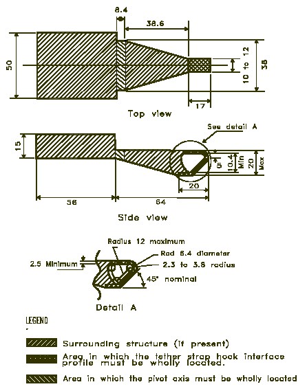 | |
| Notes: | |
| 1 | Dimensions in mm, except where otherwise indicated |
| 2 | Drawing not to scale |
| Figure 2 — Interface Profile of Tether Strap Hook with Integrated Adjustment Hardware | |
 | |
| Notes: | |
| 1 | Dimensions in mm, except where otherwise indicated. |
| 2 | Drawing not to scale. |
| 3 | Lap belt anchorage points are symmetrically located with respect to the centre SORL. |
| 4 | Maximum distance from the seat bight to the end of the buckle is 175 mm. |
| 5 | Outboard anchorage point located 700 mm from the centre SORL. |
| Figure 3 — Three-dimensional Schematic View of the Standard Seat Assembly Indicating Location of the Seat Belt Anchorage Points | |
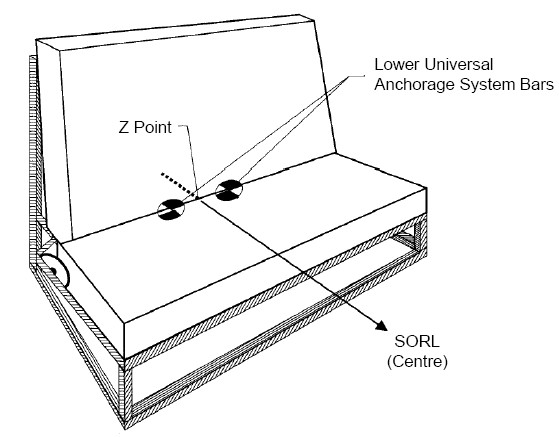 | |
| Notes: | |
| 1 | Drawing not to scale. |
| 2 | Lower universal anchorage system bars 6 mm in diameter and 25 mm in length. |
| 3 | Transverse horizontal distance between the centre of the bars and the vertical plane containing the SORL at the centre of the seat assembly is 140 mm. |
| Figure 4 — Three-dimensional Schematic View of the Standard Seat Assembly Indicating Location of the Lower Universal Anchorage System | |
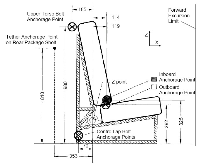 | |
| Notes: | |
| 1 | Dimensions in mm, except where otherwise indicated. |
| 2 | Drawing not to scale. |
| 3 | Anchorage point on rear package shelf located on vertical longitudinal plane containing the centre SORL. |
| Figure 5 — Side View of the Standard Seat Assembly Indicating the Location of the Seat Belt Anchorage Points | |
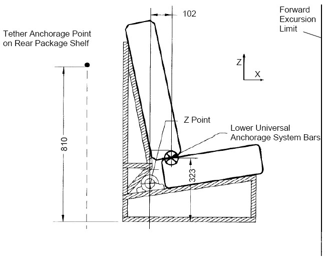 | |
| Notes: | |
| 1 | Dimensions in mm, except where otherwise indicated. |
| 2 | Drawing not to scale. |
| 3 | Anchorage point on rear package shelf located on vertical longitudinal plane containing the centre SORL. |
| 4 | Head excursion limit is 720 mm with tether attached. |
| 5 | Lower universal anchorage system bars located 102 mm forward of Z point and 323 mm upward from floor. |
| Figure 6 — Side View of the Standard Seat Assembly Indicating the Location of the Lower Universal Anchorage System | |
 | |
| Note: | |
| The illustrated limits move during dynamic testing. | |
| Figure 7 — Forward and Upper Excursion Limits for any Portion of the Target Point on Either Side of the Anthropomorphic Test Device Head |

Figure 8 — Forward-most Point of the Anthropomorphic Test Device Head on the Vertical Plane
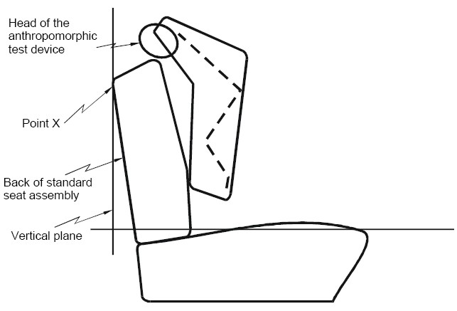
Figure 9 — Point X on the Vertical Plane of the Standard Seat Assembly
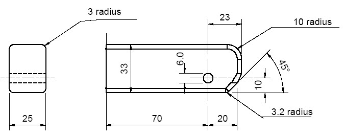 | |
| Notes: | |
| 1 | Dimensions in mm, except where otherwise indicated. |
| 2 | Drawing not to scale. |
| Figure 10 — Rear and Side View of Checking Device for Lower Connector System - Envelope Dimensions | |
- SOR/2001-341, s. 28
- SOR/2002-206, ss. 29, 30
SCHEDULE 11(Section 5.1)Lower Universal Anchorage System Symbol

- SOR/2002-206, s. 31
Page Details
- Date modified: