SCHEDULE IV(Subsections 2(1) and 5(1) and (3), section 11.2 and paragraphs 12.1(1)(c) and (2)(b) to (k))
[
SOR/95-147, s. 6
SOR/2011-264, s. 4
SOR/2020-22, s. 11
]
PART I[Repealed, SOR/2007-180, s. 5]
PART II
Controls, Tell-tales, Indicators and Sources of Illumination (Standard 101)
Interpretation
101(1) For the purposes of this section, control has the same meaning as in Technical Standards Document No. 101, Controls, Tell-tales, Indicators and Sources of Illumination (TSD 101).
General
(2) Every vehicle that is required by section 5 of these Regulations to conform to the standards set out in this section shall, in respect of the controls, tell-tales, indicators and sources of illumination that are fitted in the occupant compartment, conform to the requirements of TSD 101, as amended from time to time.
Technical Standards Document No. 101
(3) Despite S5.2.1 of TSD 101,
(a) if the left turn signal and the right turn signal each have their own control or tell-tale, the arrows in the symbol required for the turn signals control or tell-tale may be disassociated and each arrow may be used separately as a distinct symbol;
(b) if the left turn signal and the right turn signal each have their own tell-tale and the arrows in the symbol required for the turn signals tell-tale are disassociated so that each arrow is used separately as a distinct symbol, the simultaneous flashing of the left and right turn signal tell-tales may be used as the hazard warning signal tell-tale;
(c) the identification of a control set out below is not required if the control is combined with the master lighting switch:
(i) the control for the tail lamps, parking lamps, licence plate lamps, side marker lamps, identification lamps and clearance lamps, and
(ii) the headlamp lower beam control;
(d) if a single tell-tale is used to indicate more than one brake system condition, only the symbol required for the brake system malfunction shall be used;
(e) the identification of a control set out below is not required if the control is an integral part of the key-locking system of the vehicle:
(i) the engine start control, and
(ii) the engine stop control;
(f) the identification required for the drive position of the automatic transmission control may be replaced by a letter, a number, a combination of letters and numbers, or any symbol that is not set out in column 2 of the table to this section;
(g) the symbol required for the engine start control may be replaced by the word “start”;
(h) the symbol required for the engine stop control may be replaced by the word “stop”;
(i) the symbol required for the electronic stability control system malfunction tell-tale may be replaced by the abbreviation “ESC”;
(j) the symbol required for the electronic stability control system off control and tell-tale may be replaced by the abbreviation “ESC OFF”; and
(k) until September 1, 2019, the symbol required for the passenger air bag deactivated control and tell-tale may be replaced by the words “passenger air bag off” or “pass air bag off”.
Speedometers and Odometers
(4) A speedometer shall indicate the speed of the vehicle in kilometres per hour or in kilometres per hour and miles per hour. The unit or units of measurement shall be identified on the speedometer or at a location adjacent to it.
(5) A speedometer shall be illuminated whenever the vehicle’s propulsion system and headlamps are activated, unless the headlamps are being flashed for signalling purposes or are being operated as daytime running lamps.
(6) An odometer or trip odometer shall indicate distances in kilometres or in miles. If the distances are indicated in miles, that unit of measurement shall be identified at a location adjacent to the odometer or trip odometer.
Passenger Air Bag Deactivated Tell-tale
(7) The tell-tale indicating that the passenger air bag has been deactivated shall be fitted in the interior of the vehicle
(a) forward of and above the seating reference point of each front outboard designated seating position when the seat is in its forwardmost position; and
(b) in such a manner that the tell-tale, when alight, is visible to the driver and any front passenger when they are restrained by seat belts that are adjusted in accordance with the vehicle manufacturer’s instructions.
(8) Despite subsection (7), the tell-tale indicating that the passenger air bag has been deactivated
(a) shall not be fitted at or adjacent to a location that can serve for storage if an object stored at that location will obstruct the tell-tale from the view of the driver and any front passenger when they are restrained by seat belts that are adjusted in accordance with the vehicle manufacturer’s instructions; and
(b) shall not be fitted at a location where the tell-tale will not be completely visible to the driver when the driver is restrained by a seat belt that is adjusted in accordance with the vehicle manufacturer’s instructions and a rearward-facing child restraint system or an infant restraint system is installed in the forwardmost right outboard designated seating position.
Owner’s Manual
(9) The English and French versions of the owner’s manual shall contain an explanation of every symbol, word, abbreviation or letter used to identify a control, tell-tale or indicator that is fitted in the vehicle and is required to be identified under this section.
Transitional Provision
(10) Until September 1, 2019, a vehicle referred to in subsection (2) may conform to the requirements of this section as it read on the day before the day on which this subsection came into force.
TABLE
Identification of Controls, Tell-tales and Indicators
Column 1
Column 2
Column 3
Column 4
Column 5
Column 6
ITEM
SYMBOL
[RESERVED]
FUNCTION
ILLUMINATION
COLOUR
Headlamp upper beam
or
or
or
Control
Tell-tale
Blue or blue-green
Turn signals
or
Control
Tell-tale
Green
Hazard warning signal
or
Control
Yes
Tell-tale
Red
Tail lamps, parking lamps, licence plate lamps, side marker lamps, identification lamps and clearance lamps
or
Control
Yes
Windshield wiping system
Control
Yes
Windshield washing system
Control
Yes
Windshield wiping and washing system
Control
Yes
Windshield defrosting and defogging system
Control
Yes
Rear window defrosting and defogging system
Control
Yes
Brake system malfunction
Tell-tale
Red or red-orange
Antilock brake system malfunction
Tell-tale
Yellow
[RESERVED]
[RESERVED]
Antilock brake system malfunction in vehicles subject to CMVSS 121, other than trailers
Tell-tale
Yellow
Antilock brake system malfunction in trailers subject to CMVSS 121
Tell-tale
Yellow
Low brake pressure
Tell-tale
Red or red-orange
Low brake fluid
Tell-tale
Red or red-orange
Parking brake applied
Tell-tale
Red or red-orange
Brake lining wear-out condition
Tell-tale
Red or red-orange
Electronic stability control system malfunction for vehicles subject to CMVSS 126
Tell-tale
Yellow
Electronic stability control system off for vehicles subject to CMVSS 126
Control
Yes
Tell-tale
Yellow
Electronic stability control system malfunction for vehicles subject to CMVSS 136
or
or
Tell-tale
Yellow
Fuel level
or
Tell-tale
Indicator
Yes
Oil pressure
Tell-tale
Indicator
Yes
Engine coolant temperature
Tell-tale
Indicator
Yes
Battery charging
Tell-tale
Indicator
Yes
Engine stop
Control
Yes
[RESERVED]
[RESERVED]
[RESERVED]
Automatic transmission control position
Indicator
Yes
Park
P
Reverse
R
Neutral
N
Drive
D
Heating or air-conditioning fan
or
Control
Yes
[RESERVED]
[RESERVED]
[RESERVED]
Hand throttle control
Control
Engine start
Control
Manual choke control
Control
[RESERVED]
Horn
Control
Master lighting switch
or
Control
Headlamp lower beam
or
or
or
Control
Low brake air pressure
Tell-tale
Red
Seat belt unfastened
or
Tell-tale
Red
Airbag malfunction
Tell-tale
Red or yellow
Side airbag malfunction
or
Tell-tale
Red or yellow
Passenger air bag deactivated
or
Control
Tell-tale
Yellow
SOR/78-257, s. 2
SOR/86-976, s. 2
SOR/93-31, s. 3
SOR/94-374, s. 5
SOR/95-147, s. 7
SOR/95-164, s. 3
SOR/97-200, s. 3
SOR/97-421, ss. 18(E), 19(F), 20(F)
SOR/2003-272, s. 7
SOR/2007-180, s. 22(F)
SOR/2008-258, s. 7
SOR/2009-318, s. 19(F)
SOR/2009-323, s. 2
SOR/2015-24, s. 3
SOR/2017-104, ss. 3 to 5
SOR/2017-231 s. 2
Transmission Control Functions (Standard 102)
[
SOR/97-421, s. 3
]
102(1) Any automatic transmission fitted on a vehicle shall have
(a) its control positions in such a sequence that
(i) movement between any forward and reverse drive position may be made only through a neutral position,
(ii) in the case of a steering-column-mounted control, movement from the neutral position to any forward drive position may be made in a clockwise direction only, and
(iii) the park position, if included in the sequence, is located at the end of the sequence adjacent to the reverse drive position; and
(b) one forward drive position that, in vehicles having more than one forward transmission gear ratio, provides a greater degree of engine braking than the highest speed transmission ratio at speeds below 40 km/h.
(2) On any vehicle equipped with an automatic transmission, a motor used for the vehicle’s propulsion must not be started by setting the ignition switch to the position used to start the motor if the transmission control is in a forward or reverse drive position.
(2.1) If a passenger car, multi-purpose passenger vehicle, truck or three-wheeled vehicle has a GVWR of 4 536 kg or less and a transmission control sequence that includes a park position, the transmission control must not be capable of shifting from the park position to the forward or reverse drive position — while a motor used for the vehicle’s propulsion is in use — unless the service brake pedal is depressed or the service brakes are otherwise engaged.
(3) Subject to subsection (5), where the transmission control sequence includes a park position, the identification of the transmission control positions and the position selected shall be displayed in at least a single location in view of the driver when
(a) the ignition switch is set to the position where the transmission can be shifted; or
(b) the transmission control is not in the park position.
(4) Subject to subsection (5), if the transmission control sequence does not include a park position, the identification of the transmission control positions and the position selected shall be displayed in at least a single location in view of the driver when the ignition switch is set to the position where the engine is capable of operation.
(5) The identification of transmission control positions need not be displayed when the ignition switch is set to the position used to start the vehicle.
(6) The identification of the transmission control positions and sequence, on vehicles equipped with a manual transmission, shall be permanently displayed in view of the driver.
(7) If a passenger car, multi-purpose passenger vehicle, truck or three-wheeled vehicle has a GVWR of 4 536 kg or less and is equipped with a manual transmission, a motor used for the vehicle’s propulsion must not be started by setting the ignition switch to the position used to start the motor unless the clutch pedal is depressed or the drive train is otherwise disengaged.
(8) In this section, drive train means the components that transfer motive power from the motor to the drive wheels.
SOR/95-164, s. 4
SOR/97-421, ss. 4, 22(F)
SOR/2003-189, s. 1
SOR/2003-272, s. 34
SOR/2006-94, s. 4(E)
SOR/2007-246, s. 2
Windshield Defrosting and Defogging
103(1) In this section,
critical area
critical area means area C as referred to in section 104 of this Schedule; (zone critique)
defog
defog means to remove moisture from the inside surface of the glass; (désembuer)
defrost
defrost means to melt frost or ice on the inside or outside surface of the glass; (dégivrer)
entire windshield
entire windshield means area A as referred to in section 104 of this Schedule; (pare-brise tout entier)
road load
road load means the power output required to move the vehicle at the curb mass plus 180 kg on level, clean, dry, smooth portland cement concrete pavement or other surface with an equivalent coefficient of surface friction at a specified speed through still air at 20°C and a standard barometric pressure of 101.3 kPa, and includes driveline friction, rolling friction and air resistance. (charge de route)
(2) Subject to subsection (2.1), every vehicle shall be equipped with a windshield defrosting and defogging system.
(2.1) A three-wheeled vehicle that is equipped with a windshield shall be equipped with a windshield defrosting and defogging system.
(3) In the case of a passenger car or a three-wheeled vehicle, the windshield defrosting and defogging system shall
(a) meet the requirements of section 3 of SAE Recommended Practice J902 Passenger Car Windshield Defrosting Systems, (August 1964), when tested in accordance with paragraph (b) except that the areas referred to in that section as “critical area” and “entire windshield” shall be as referred to in subsection (1) of this section; and
(b) be tested in accordance with such of the portions of paragraphs 4.1 to 4.4.7 of SAE Recommended Practice J902, (August 1964), or SAE Recommended Practice J902a, (March 1967), as are applicable to that system.
(4) Despite the testing requirements set out in subsection (3) for the windshield defrosting and defogging system of a passenger car or three-wheeled vehicle,
(a) in the case of a passenger car or three-wheeled vehicle equipped with a heating system other than a heat exchanger type that uses the engine’s coolant as a means to supply the heat to the heat exchanger, the procedure specified by the vehicle’s manufacturer for cold weather starting shall be followed during the entire test period, except that the use of a power or heat source external to the vehicle is not permitted;
(b) in the case of all other passenger cars and three-wheeled vehicles,
(i) during the entire test period, the engine speed shall not exceed 1,500 revolutions per minute in neutral gear or the engine speed and load shall not exceed the speed and load at 40 km/h (25 miles per hour) in the manufacturer’s recommended gear with road load, or
(ii) during the first 5 minutes of the test period, the warm-up procedure recommended by the vehicle’s manufacturer for cold weather starting shall be followed and during the last 35 minutes of the test period, the procedure referred to in subparagraph (i) shall be followed;
(c) a room air change of 90 times per hour is not required;
(d) the windshield wipers may be used during the test if they are operated without manual assistance;
(e) one or two windows may be open a total of 25 mm;
(f) the defroster blower may be turned on at any time;
(g) the wind velocity is at any level from 0 to 3 km/h; and
(h) the test chamber temperature and the wind velocity shall be measured after the engine has been started, at the forwardmost point of the vehicle or a point 91.4 cm (36 inches) from the base of the windshield, whichever is farther forward, at a level halfway between the top and the bottom of the windshield on the vehicle centreline.
SOR/97-264, s. 1
SOR/2003-272, s. 8
SOR/2008-104, s. 9
Windshield Wiping and Washing System
104(1) In this section,
areas A, B and C
areas A, B and C means the areas referred to in Column I of Tables I, II, III and IV to this section when established as shown in Figures 1 and 2 of SAE Recommended Practice J903a Passenger Car Windshield Wiper Systems, (May 1966), using the angles specified in Columns III to VI of the above Tables; (zones A, B et C)
daylight opening
daylight opening means the maximum unobstructed opening through the glazing surface as defined in paragraph 2.3.12 of Section E, Ground Vehicle Practice, SAE Aerospace-Automotive Drawing Standards, (September 1963); (ouverture de jour)
glazing surface reference line
glazing surface reference line means the intersection of the glazing surface and a horizontal plane 635 mm above the seating reference point, as shown in Figure 1 of SAE Recommended Practice J903a (May 1966); (ligne de référence de la surface vitrée)
overall width
overall width means the maximum overall body width dimension W116 as defined in Section E, Ground Vehicle Practice, SAE Aerospace-Automotive Drawing Standards, (September 1963); (largeur hors tout)
plan view reference line
plan view reference line means,
(a) in respect of vehicles with a bench type front seat, a line parallel to the longitudinal centreline of the vehicle and outboard of the centre of the steering wheel by a distance equal to 0.15 times the difference between one-half the shoulder room dimension and the steering wheel centre offset, as shown in Figure 2 of SAE Recommended Practice J903a, (May 1966); and
(b) in respect of vehicles with individual front seats,
(i) a line parallel to the longitudinal centreline of the vehicle which passes through the centre of the driver’s designated seating position, or
(ii) a line parallel to the longitudinal centreline of the vehicle located so that the geometric centre of the 95 per cent eye range contour is positioned on the longitudinal centreline of the driver’s designated seating position; (ligne de référence longitudinale)
shoulder room dimension
shoulder room dimension means the front shoulder room dimension W3 as defined in Section E, Ground Vehicle Practice, SAE Aerospace-Automotive Drawing Standards, (September 1963); (espace d’épaules)
95 per cent eye range contour
95 per cent eye range contour means the 95th percentile tangential cut-off specified in SAE Recommended Practice J941a Passenger Car Driver’s Eye Range, (August 1967). (95 pour cent du contour de portée visuelle)
(2) For the purposes of this section, the expressions “manikin H-point”, “manikin H-point with seat in rearmost position”, and “H-point” used in an SAE Standard or SAE Recommended Practice mean “seating reference point”.
(3) Subject to subsection (3.1), every vehicle shall have a power-driven windshield wiping system that has at least two frequencies or speeds and that has, irrespective of engine speed and engine load,
(a) one frequency or speed of at least 45 cycles per minute;
(b) a difference of at least 15 cycles per minute between the highest frequency or speed and one of the lower frequencies or speeds; and
(c) the lower frequency or speed referred to in paragraph (b) equal to at least 20 cycles per minute.
(3.1) A three-wheeled vehicle that is equipped with a windshield shall have a windshield wiping system that conforms to the requirements of subsection (3).
(4) Compliance with subsection (3) shall be demonstrated by testing under the conditions specified in sections 4.1.1 and 4.1.2 of SAE Recommended Practice J903a, (May 1966).
(5) In the case of a passenger car or a three-wheeled vehicle, the windshield wiping system, when tested wet in accordance with SAE Recommended Practice J903a (May 1966), shall wipe the percentage of areas A, B and C of the windshield that
(a) is specified in Column II of whichever of Tables I, II, III or IV to this section is applicable; and
(b) is within the area bounded by a perimeter line on the glazing surface 25 mm from the edge of the daylight opening.
(6) Subject to subsection (7), every vehicle shall have a windshield washing system that meets the requirements of SAE Recommended Practice J942, Passenger Car Windshield Washer Systems (November 1965), except that the words “the effective wipe pattern defined in SAE J903, paragraph 3.1.2” in paragraph 3.1 of SAE Recommended Practice J942 shall be replaced
(a) in the case of a passenger car or a three-wheeled vehicle, by the words “the areas established in accordance with the definition of areas A, B and C in subsection (1) of Canada Motor Vehicle Safety Standard No. 104”; and
(b) in the case of a multi-purpose passenger vehicle, truck or bus, by the words “the pattern designed by the manufacturer for the windshield wiping system on the exterior surface of the windshield glazing”.
(7) A three-wheeled vehicle that is equipped with a windshield shall have a windshield washing system that meets the requirements of subsection (6).
TABLE I
Passenger Cars and Three-Wheeled Vehicles of Less Than 1 520 mm Overall Width
Column I
Column II
Column III
Column IV
Column V
Column VI
Area
Minimum Percentage to be wiped
Angle in degrees
Left
Right
Up
Down
A
80
16
49
7
5
B
94
13
46
4
3
C
99
7
15
3
1
TABLE II
Passenger Cars and Three-Wheeled Vehicles of 1 520 mm or More But Less Than 1 630 mm Overall Width
Column I
Column II
Column III
Column IV
Column V
Column VI
Area
Minimum Percentage to be wiped
Angle in degrees
Left
Right
Up
Down
A
80
17
51
8
5
B
94
13
49
4
3
C
99
7
15
3
1
TABLE III
Passenger Cars and Three-Wheeled Vehicles of 1 630 mm or More But Less Than 1 730 mm Overall Width
Column I
Column II
Column III
Column IV
Column V
Column VI
Area
Minimum Percentage to be wiped
Angle in degrees
Left
Right
Up
Down
A
80
17
53
9
5
B
94
14
51
5
3
C
99
8
15
4
1
TABLE IV
Passenger Cars and Three-Wheeled Vehicles of 1 730 mm or More Overall Width
Column I
Column II
Column III
Column IV
Column V
Column VI
Area
Minimum Percentage to be wiped
Angle in degrees
Left
Right
Up
Down
A
80
18
56
10
5
B
94
14
53
5
3
C
99
10
15
5
1
SOR/94-670, s. 2(F)
SOR/97-264, s. 2
SOR/2002-55, s. 21
SOR/2003-272, s. 9
SOR/2006-94, s. 4(E)
SOR/2008-104, s. 10
Hydraulic and Electric Brake Systems (Standard 105)
105(1) Subject to section 135 of this Schedule, every multi-purpose passenger vehicle, truck and bus shall conform to the requirements of Technical Standards Document No. 105, Hydraulic and Electric Brake Systems (TSD 105), as amended from time to time.
(2) An indicator lamp referred to in S5.3 of TSD 105 shall, when activated due to a condition set out in S5.3.1 of TSD 105, display the identification symbol set out in the table to section 101 of this Schedule that corresponds to that condition, but if the vehicle is fitted with a single common indicator lamp, the lamp shall display the identification symbol for a brake system malfunction set out in the table to section 101 of this Schedule.
(3) The statement set out in S5.4.3 of TSD 105 may be replaced by another statement to the same effect.
(4) to (6)[Repealed, SOR/2015-24, s. 4]
SOR/79-374, s. 3
SOR/80-637, s. 1
SOR/86-683, s. 3
SOR/86-976, s. 3
SOR/91-144, s. 1
SOR/96-89, s. 2
SOR/97-200, ss. 4, 6
SOR/97-421, s. 5
SOR/98-524, s. 4(F)
SOR/99-357, s. 3
SOR/2001-35, s. 4
SOR/2005-42, s. 13
SOR/2008-104, s. 11
SOR/2009-79, s. 1
SOR/2009-318, s. 19(F)
SOR/2011-238, s. 1
SOR/2015-24, s. 4
Brake Hoses (Standard 106)
[
SOR/93-561, s. 3
SOR/2011-238, s. 1
]
106(1) Every brake hose, brake hose assembly and brake hose end fitting with which a passenger car, multi-purpose passenger vehicle, truck, bus, three-wheeled vehicle, motorcycle, trailer, and trailer converter dolly are equipped shall conform to the requirements of Technical Standards Document No. 106, Brake Hoses (TSD 106), as amended from time to time.
(2) A reference in TSD 106 to a standard published by ASTM that is set out in column 1 of the table to this subsection may be read as a reference to the standard set out opposite that standard in column 2 of the table.
TABLE
Item
Column 1
Column 2
1
ASTM B 117 – 03, Standard Practice for Operating Salt Spray (Fog) Apparatus
ASTM B 117 – 07a, Standard Practice for Operating Salt Spray (Fog) Apparatus
2
ASTM D 471 – 98ε1, Standard Test Method for Rubber Property — Effect of Liquids
ASTM D 471 – 06ε1, Standard Test Method for Rubber Property — Effect of Liquids
3
ASTM D 4329 – 99, Standard Practice for Fluorescent UV Exposure of Plastics
ASTM D 4329 – 05, Standard Practice for Fluorescent UV Exposure of Plastics
4
ASTM E 4 – 03, Standard Practices for Force Verification of Testing Machines
ASTM E 4 – 08, Standard Practices for Force Verification of Testing Machines
5
ASTM G 151 – 97, Standard Practice for Exposing Nonmetallic Materials in Accelerated Test Devices that Use Laboratory Light Sources
ASTM G 151 – 06, Standard Practice for Exposing Nonmetallic Materials in Accelerated Test Devices that Use Laboratory Light Sources
6
ASTM G 154 – 00, Standard Practice for Operating Fluorescent Light Apparatus for UV Exposure of Nonmetallic Materials
ASTM G 154 – 06, Standard Practice for Operating Fluorescent Light Apparatus for UV Exposure of Nonmetallic Materials
(3)[Repealed, SOR/2014-307, s. 1]
SOR/79-677, s. 3
SOR/79-907, s. 1
SOR/93-561, s. 4
SOR/97-421, s. 16
SOR/2007-180, s. 6
SOR/2009-318, s. 8
SOR/2009-330, s. 1
SOR/2011-238, s. 1
SOR/2014-307, s. 1
107[Repealed, SOR/96-437, s. 2]
Lighting Systems and Reflective Devices (Standard 108)
Passenger Cars, Multi-purpose Passenger Vehicles, Trucks, Trailers and Buses
108(1) Every passenger car, multi-purpose passenger vehicle, truck, trailer and bus shall conform to Technical Standards Document No. 108, Lamps, Reflective Devices, and Associated Equipment (TSD 108), as amended from time to time.
Three-wheeled Vehicles
(2) Every three-wheeled vehicle shall be equipped with lamps, reflex reflectors and associated components as required under subsection (1) for passenger cars, and
(a) if an outermost parking lamp is installed more than 400 mm from the nearest of the two outer edges of the vehicle that are used to determine the overall width of the vehicle, with a white forward-facing reflex reflector that is installed not more than 400 mm from that edge to indicate the width of the vehicle; and
(b) if an outermost tail lamp or outermost rear reflex reflector is installed more than 400 mm from the nearest of the two outer edges of the vehicle that are used to determine the overall width of the vehicle, with a red rearward-facing reflex reflector that is installed not more than 400 mm from that edge to indicate the width of the vehicle.
Alternative Lamps for Passenger Cars, Three-wheeled Vehicles, Multi-purpose Passenger Vehicles, Trucks and Buses
(3) Subject to subsection (4), instead of being equipped with headlamps as required under subsection (1) or (2), as the case may be, passenger cars, three-wheeled vehicles, multi-purpose passenger vehicles, trucks and buses may be equipped with adaptive driving beam lamps that conform to SAE Recommended Practice J3069, Adaptive Driving Beam (June 2016), except that the lamps shall not be capable of activation or deactivation by pedal.
(4) If the adaptive driving beam is formed by the entirety or a portion of an upper beam or lower beam, or both, the lamps shall also conform to TSD 108, except that despite S10.18, horizontal aim adjustment is allowed.
(5) Instead of being equipped with headlamps as required under subsection (1) or (2), as the case may be, passenger cars, three-wheeled vehicles, multi-purpose passenger vehicles, trucks and buses may be equipped with headlamps that
(a) in the case of a passenger car, multi-purpose passenger vehicle, truck or bus, conform to
(i) United Nations Regulation No. 8, Uniform Provisions Concerning the Approval of Motor Vehicle Headlamps Emitting an Asymmetrical Passing Beam or a Driving Beam or Both and Equipped with Halogen Filament Lamps (H1, H2, H3, HB3, HB4, H7, H8, H9, HIR1, HIR2 and/or H11), as amended from time to time,
(ii) United Nations Regulation No. 20, Uniform Provisions Concerning the Approval of Motor Vehicle Headlamps Emitting an Asymmetrical Passing Beam or a Driving Beam or Both and Equipped with Halogen Filament Lamps (H4 Lamps), as amended from time to time,
(iii) United Nations Regulation No. 31, Uniform Provisions Concerning the Approval of Power-Driven Vehicle’s Halogen Sealed-beam Headlamps (HSB) Emitting a European Asymmetrical Passing Beam or a Driving Beam or Both, as amended from time to time,
(iv) United Nations Regulation No. 98, Uniform Provisions Concerning the Approval of Motor Vehicle Headlamps Equipped with Gas-discharge Light Sources, as amended from time to time, or
(v) United Nations Regulation No. 112, Uniform Provisions Concerning the Approval of Motor Vehicle Headlamps Emitting an Asymmetrical Passing-beam or a Driving-beam or Both and Equipped with Filament Lamps and/or Light-emitting Diode (LED) Modules, as amended from time to time;
(b) in the case of a three-wheeled vehicle, conform to
(i) the regulation referred to in subparagraph (a)(i), (ii) or (v), or
(ii) the regulation referred to in subparagraph (a)(iii) or (iv), as if the vehicle were a passenger car;
(c) are installed on the vehicle in such a manner as to produce only a beam pattern for right-hand traffic, and, if the vehicle is fitted with a mechanism that allows the headlamps to produce a beam pattern for left-hand traffic, that mechanism is inoperative; and
(d) conform to, as applicable, the physical tests referred to in the following provisions of TSD 108:
(i) S10.13.4,
(ii) S10.14.7, and
(iii) S10.15.7.
(6) Instead of being equipped with headlamps in accordance with subsection (1) or (2), as the case may be, passenger cars, three-wheeled vehicles, multi-purpose passenger vehicles, trucks and buses may be equipped with headlamps that conform to United Nations Regulation No. 123, Uniform Provisions Concerning the Approval of Adaptive Front-lighting Systems (AFS) for Motor Vehicles, as amended from time to time.
(7) The headlamps referred to in subsection (6) shall
(a) be installed
(i) in accordance with paragraph 6.22 of United Nations Regulation No. 48, Uniform Provisions Concerning the Approval of Vehicles with Regard to the Installation of Lighting and Light-signalling Devices, as amended from time to time, except that, despite paragraph 6.22.6.2, the automatic levelling device is mandatory in all cases, and
(ii) in such a manner as to produce only a beam pattern for right-hand traffic and, if the vehicle is fitted with a mechanism that allows the headlamps to produce a beam pattern for left-hand traffic, that mechanism shall be inoperative; and
(b) above a mounting height of 850 mm, have a maximum intensity that does not exceed the intensity requirements under TSD 108 for upper beam headlamps where the mounting height is measured to the centre of the highest mounted lamp.
(8) For the purposes of subsections (5) and (6), the following requirements of the United Nations Regulations referred to in those subsections do not apply:
(a) any requirements respecting the type-approval process;
(b) any requirements respecting the marking of type-approved headlamps; and
(c) any requirements respecting
(i) the conformity of production of type-approved headlamps,
(ii) the penalties for non-conformity of production, and
(iii) the modification of a headlamp type and extension of approval.
(9) For the purposes of subsection (6) and subparagraph (7)(a)(i), United Nations Regulations Nos. 48 and 123 are considered to be applicable to three-wheeled vehicles, despite any provision to the contrary in those Regulations.
Motorcycles Other than Motor Tricycles
(10) Every motorcycle other than a motor tricycle shall conform to TSD 108, except that
(a) S6.1.3.5.1 (Vertical headlamp arrangement) does not apply; and
(b) despite S10.18, S10.18.1 applies to motorcycles except that “both vertical and horizontal aim” shall be read as “the vertical aim”.
Motor Tricycles
(11) Every motor tricycle shall conform to TSD 108, except that
(a) the following provisions of TSD 108 do not apply:
(i) S6.1.3.5.1 (Vertical headlamp arrangement), and
(ii) S10.17.1.2.2 (distance between headlamps);
(b) despite S10.18, S10.18.1 applies to motor tricycles except that “both vertical and horizontal aim” shall be read as “the vertical aim”;
(c) despite S6.1.1 and S6.1.3.1 and Table I-c, a motor tricycle shall be equipped with tail lamps, stop lamps and reflex reflectors in the number and at the mounting locations specified in Table I-a for passenger cars; and
(d) instead of being equipped with headlamps as specified in S6.1 and Table I-c, a motor tricycle may be equipped with lower beam headlamps and upper beam headlamps as specified in S6.1 and Table I-a for passenger cars.
(12) In addition to being equipped with reflex reflectors and lamps as specified in S6.1 and Table I-c of TSD 108, a motor tricycle shall be
(a) equipped with parking lamps as specified in S6.1 and Table I-a of TSD 108 for passenger cars;
(b) if an outermost parking lamp is installed more than 400 mm from the nearest of the two outer edges of the motor tricycle that are used to determine the overall width of the motor tricycle, equipped with a white forward-facing reflex reflector that is installed not more than 400 mm from that edge to indicate the width of the motor tricycle; and
(c) if an outermost tail lamp or outermost rear reflex reflector is installed more than 400 mm from the nearest of the two outer edges of the motor tricycle that are used to determine the overall width of the motor tricycle, equipped with a red rearward-facing reflex reflector that is installed not more than 400 mm from that edge to indicate the width of the motor tricycle.
Alternative Headlamps for Motorcycles
(13) Instead of being equipped with headlamps as required under subsection (10) or (11), as the case may be, motorcycles may be equipped with headlamps that
(a) conform to
(i) subsection (5),
(ii) United Nations Regulation No. 57, Uniform Provisions Concerning the Approval of Headlamps for Motor Cycles and Vehicles Treated as Such, as amended from time to time,
(iii) United Nations Regulation No. 72, Uniform Provisions Concerning the Approval of Motor Cycle Headlamps Emitting an Asymmetrical Passing Beam and a Driving Beam and Equipped with Halogen Lamps (HS1 Lamps), as amended from time to time, or
(iv) United Nations Regulation No. 113, Uniform Provisions Concerning the Approval of Motor Vehicle Headlamps Emitting a Symmetrical Passing Beam or a Driving Beam or Both and Equipped with Filament, Gas-discharge Light Sources or LED Modules, as amended from time to time;
(b) are installed in accordance with the requirements of paragraphs 5.7, 5.11, 5.13, 6.1 and 6.2 of United Nations Regulation No. 53, Uniform Provisions Concerning the Approval of Category L3 Vehicles with Regard to the Installation of Lighting and Light-Signalling Devices, as amended from time to time; and
(c) in the case of headlamps conforming to a Regulation referred to in subparagraph (a)(ii), (iii) or (iv), conform to
(i) the performance requirements of the vibration test, moisture test, dust test and corrosion test described in S14.5 of TSD 108, and
(ii) in the case of headlamps that do not incorporate a glass lens, the performance requirements of the plastic optical materials tests described in S14.4 of TSD 108.
(14) For the purposes of subsection (13), the following requirements of the United Nations Regulations referred to in that subsection do not apply:
(a) any requirements respecting the type-approval process;
(b) any requirements respecting the marking of type-approved headlamps; and
(c) any requirements respecting
(i) the conformity of production of type-approved headlamps,
(ii) the penalties for non-conformity of production, and
(iii) the modification of a headlamp type and extension of approval.
Restricted-use Motorcycles
(15) Every restricted-use motorcycle shall be equipped with reflex reflectors as required under subsection (10) for motorcycles other than motor tricycles.
Additional Requirements for the Activation of Certain Lamps
(16) In addition to being activated as specified in Table I-a of TSD 108, parking lamps, tail lamps, licence plate lamps and side marker lamps on a passenger car, multi-purpose passenger vehicle, three-wheeled vehicle, truck or bus shall be activated
(a) while the front fog lamps on the vehicle are activated in a steady-burning state other than as daytime running lamps; or
(b) while the rear fog lamps on the vehicle are activated in a steady-burning state.
(17) Except when it is used to give intermittent luminous warnings at short intervals, the upper beam may be activated only when the master light switch is in the “headlamps on” position or in the “AUTO” (automatic) position and the conditions for automatic activation of the lower beam exist.
(18) Despite S6.1.5 and Table I-a of TSD 108, the tail lamps may be activated without the concurrent activation of the headlamps or parking lamps, if the daytime running lamps are activated.
(19) Beginning on September 1, 2021, if the fuel level indicator, oil pressure indicator, engine coolant temperature indicator, battery charging indicator, transmission control position indicator or speedometer indicator or their identifications are illuminated when the daytime running lights of a vehicle are in use,
(a) the lower beam headlamps shall
(i) automatically activate in a steady-burning state in less than two seconds when the ambient light outside the vehicle is less than 1,000 lux while the transmission control is in the forward or reverse position and the vehicle is in motion, unless the lower beam headlamps were deactivated manually after their automatic activation following the most recent disarming of the immobilization system in accordance with section 114, and
(ii) automatically deactivate under the conditions set out by the manufacturer; or
(b) the tail lamps shall be alight.
(20) For the purposes of paragraph (19)(a), the ambient light outside a vehicle shall be measured on a horizontal surface, with a cosine corrected sensor at the same height as the mounting position of the ambient light sensor on the vehicle.
Fog Lamps and Forward Auxiliary Road Illumination Lamps — Aiming Adjustment Mechanism
(21) Every passenger car, multi-purpose passenger vehicle, three-wheeled vehicle, motor tricycle, truck and bus equipped with a front fog lamp or forward auxiliary road illumination lamp shall be equipped with a mechanism for that lamp that
(a) allows aim adjustment of the vertical aim by one person to maintain the beam pattern of the lamp within the full range of vertical pitch of the vehicle, with the use of ordinarily available tools; and
(b) allows the adjustment referred to in paragraph (a) after being subjected to the corrosion test procedure set out in S14.6.3.1 of TSD 108.
Information
(22) There shall be provided, in the owner’s manual, with every passenger car, multi-purpose passenger vehicle, truck and bus, the information required by TSD 108 in relation to the safe operation of the lighting systems and reflective devices of the vehicle.
(23) There shall be provided, in the owner’s manual, with every three-wheeled vehicle, information relating to the safe operation of the lighting systems and reflective devices of the vehicle that is the same as the information required by TSD 108 in relation to passenger cars.
(24) Except for the words “sealed beam” referred to in S6.5.3.3.1 of TSD 108 and the word “motorcycle” referred to in S10.17.2 of TSD 108, any information required under this section to be marked on a passenger car, multi-purpose passenger vehicle, three-wheeled vehicle, motorcycle, restricted-use motorcycle, trailer, truck or bus shall be in English and French.
Daytime Running Lamps
(25) Subsections (26) to (30) apply to passenger cars, multi-purpose passenger vehicles, trucks, buses and three-wheeled vehicles.
(26) Every vehicle shall be equipped with daytime running lamps
(a) in accordance with S6.1.3.1 of TSD 108, except that the reference to “applicable photometric requirements” in that provision is a reference to the applicable photometric requirements set out in SAE Standard J2087, Daytime Running Light (August 2017) (SAE Standard J2087);
(b) in accordance with S6.2 of TSD 108, except that the references in that provision to “lighting equipment required by this TSD” and to “required lamp” include a reference to “daytime running lamp”; and
(c) that conform to
(i) sections 5, 6 and 7.3.1 of SAE Standard J2087, except that despite section 6.1.2, if a daytime running lamp is optically combined with a white front position lamp that has a projected luminous lens area of 200 cm2 or less, it may conform to the light intensity distribution values shown in figure 1 when tested in accordance with section 5.1, or
(ii) until September 1, 2020, SAE Standard J583, Front Fog Lamps (September 2016) (SAE Standard J583).
(27) Despite section 6.4 of SAE Standard J2087, the light from a daytime running lamp shall be
(a) if the lamp is optically combined with a parking lamp, white or yellow;
(b) if produced by a turn signal lamp, yellow; and
(c) in all other cases, white.
Switching — Daytime Running Lamps
(28) Subject to subsections (29) and (30), the daytime running lamps on a vehicle shall be activated not later than when the vehicle is set in motion under its own power and shall remain activated until the motors or engines used for the vehicle’s propulsion are switched off and as a result the vehicle enters a mode of operation other than “accessory” or “on”.
(29) The daytime running lamps on a vehicle shall
(a) be deactivated while the lower beam headlamps are activated to provide road illumination;
(b) beginning on September 1, 2020, be deactivated while the front fog lamps provide road illumination after being activated by the driver; and
(c) if they also serve as front turn signal lamps,
(i) be deactivated on the side of the vehicle where a turn signal is activated, while that turn signal is activated, and
(ii) be deactivated on both sides of the vehicle while the hazard warning signal is activated.
(30) The daytime running lamps on a vehicle may be
(a) deactivated while the parking brake is applied or the transmission control is in the park or neutral position and the vehicle is not in motion;
(b) deactivated while the headlamps are being flashed for signalling purposes;
(c) switched off manually, in which case they shall reactivate automatically, at the discretion of the manufacturer, either not later than when the vehicle travels more than 100 m or when the speed of the vehicle exceeds 10 km/h; and
(d) wired to flash for signalling purposes.
Motorcycle Running Lamps
(31) The following lamps on a motorcycle shall be activated not later than when the motorcycle is set in motion under its own power and shall remain activated until the motorcycle’s main electrical system is turned off or until the motorcycle is put in the “accessory” mode of operation:
(a) every tail lamp;
(b) every licence plate lamp; and
(c) every headlamp or, as an alternative, one or two lamps that conform to the requirements for dedicated daytime running lamps set out in SAE Standard J2087.
TSD 108
(32) For the purposes of this section, “equipment” in TSD 108 shall be read as “component”.
United Nations Regulations
(33) For the purposes of this section,
(a) “dipped beam” and “passing beam” in United Nations Regulations Nos. 8, 20, 31, 48, 53, 57, 72, 98, 112, 113 and 123 shall be read as “lower beam” or as “lower beam headlamp”, as the context requires; and
(b) “driving beam” and “main beam” in United Nations Regulations Nos. 8, 20, 31, 48, 53, 57, 72, 98, 112, 113 and 123 shall be read as “upper beam” or as “upper beam headlamp”, as the context requires.
SAE
(34) For the purposes of section 7.3.1 of SAE Standard J2087 and section 5.2.5.1 of SAE Standard J583, “should” shall be interpreted as expressing an obligation.
Transitional Provision
(35) Despite subsections (1) to (34), a vehicle may, until August 31, 2019, conform to the requirements of this section that are applicable to a lighting system or reflective device, as they read immediately before the day on which this subsection comes into force.
SOR/79-306, s. 3
SOR/80-636, s. 2
SOR/84-812, s. 3
SOR/86-979, s. 1
SOR/87-497, s. 2
SOR/87-660, s. 4
SOR/88-268, s. 5
SOR/91-692, s. 2
SOR/94-374, s. 5
SOR/94-692, s. 2(F)
SOR/95-147, s. 8
SOR/95-164, s. 5
SOR/96-366, s. 5
SOR/97-421, ss. 16, 18(E), 22(F)
SOR/99-112, s. 1
SOR/99-426, s. 1
SOR/2000-182, s. 5
SOR/2001-60, s. 1
SOR/2001-116, s. 1
SOR/2001-353, s. 2
SOR/2003-272, s. 10
SOR/2005-42, ss. 1, 2
SOR/2006-94, s. 4(E)
SOR/2008-104, s. 12
SOR/2009-330, s. 2
SOR/2014-307, s. 2
SOR/2015-23, s. 3
SOR/2018-43, s. 4
108.1[Repealed, SOR/2018-43, s. 4]
109[Repealed, SOR/79-339, s. 3]
Tire Selection and Rims for Motor Vehicles With a GVWR of 4 536 KG or Less (Standard 110)
General
110(1) Every motor vehicle with a GVWR of 4 536 kg or less — except motorcycles other than motor tricycles equipped with passenger car tires, restricted-use motorcycles, three-wheeled vehicles equipped with tires other than passenger car tires and low-speed vehicles — and every tire rim manufactured for use on those vehicles must conform to the requirements of Technical Standards Document No. 110, Tire Selection and Rims for Motor Vehicles With a GVWR of 4 536 kg or Less (TSD 110), as amended from time to time.
Technical Standards Document No. 110
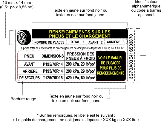
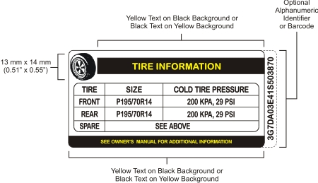
(2) Except as provided in subsections (3) and (4), the information specified in S4.3 and S4.3.5 of TSD 110 shall appear, at the option of the manufacturer, either
(a) in both official languages on one vehicle placard, as shown in Figure 3, or, if the manufacturer chooses to use a tire inflation pressure label, on one placard and one label, as shown in Figures 3 and 6; or
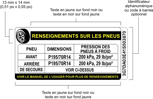
(b) in each official language on two vehicle placards, as shown in Figures 1 and 2, or, if the manufacturer chooses to use a tire inflation pressure label, on two placards and two labels, as shown in Figures 1, 2, 4 and 5, affixed at the same location on the vehicle but apart.
(3) The information specified in S4.3(f) of TSD 110 that appears on a vehicle placard and, at the manufacturer’s option, on a tire inflation pressure label, in accordance with paragraph (2)(a), shall appear either
(a) in the form of the symbol number N.03 for Operator’s manual, operation instructions, that is included in International Standard ISO 2575, entitled Road vehicles — Symbols for controls, indicators and tell-tales, 7th edition, May 1, 2004; or
(b) in both official languages on one placard, as shown in Figure 3, or on one placard and one label, as shown in Figures 3 and 6.
(4) The information specified in S4.3(f) of TSD 110 that appears on a vehicle placard and, at the manufacturer’s option, on a tire inflation pressure label, in accordance with paragraph 2(b), shall appear either
(a) in the form of the symbol number N.03 specified in paragraph (3)(a); or
(b) in each official language on two placards, as shown in Figures 1 and 2, or on two placards and two labels, as shown in Figures 1, 2, 4 and 5, affixed at the same location on the vehicle but apart.
(5) The words “Voir le manuel de l’usager pour plus de renseignements”, in the French version of the information specified in S4.3(f) of TSD 110, may, at the option of the manufacturer, be replaced by the words “Voir le guide du propriétaire pour plus de renseignements”, “Voir le manuel du propriétaire pour plus de renseignements” or “Voir le guide de l’automobiliste pour plus de renseignements”.
(6) The information specified in S4.3.3 of TSD 110 shall be in both official languages.
(7) The following definitions apply for the purposes of TSD 110.
load rating
load rating means the maximum load a tire is rated to carry at a given inflation pressure. (charge nominale)
maximum load rating
maximum load rating means the load rating at the maximum permissible inflation pressure for that tire. (limite de charge nominale)
rim base
rim base means that portion of a rim remaining after the removal of all split or continuous rim flanges, side rings, and locking rings that can be detached from the rim. (base de jante)
Load Range Identification Symbol
(8) In the case of vehicles equipped with light-truck tires, the load range identification symbol shall appear either on the compliance label required by section 6 of these Regulations or on the vehicle placard or tire inflation pressure label, after the tire size designation.
(9)[Repealed, SOR/2014-307, s. 3]
Figure 1 — Vehicle Placard, Unilingual English Example
Figure 2 — Vehicle Placard, Unilingual French Example
Figure 3 — Vehicle Placard, Bilingual Example
Figure 4 — Tire Inflation Pressure Label, Unilingual English Example
Figure 5 — Tire Inflation Pressure Label, Unilingual French Example
Figure 6 — Tire Inflation Pressure Label, Bilingual Example
SOR/79-339, s. 3
SOR/79-940, s. 7
SOR/87-448, s. 1
SOR/2003-272, s. 12
SOR/2008-258, s. 8
SOR/2014-82, s. 1
SOR/2014-307, s. 3
SOR/2020-22, s. 12
Mirrors and Rear Visibility Systems
Mirrors
General
111(1) Any mirror referred to in this section that is installed on a vehicle shall
(a) have a stable support;
(b) be adjustable in the horizontal and vertical directions;
(c) be a unit magnification mirror, except in the cases referred to in subsection (6), paragraph (13)(b) and subsection (16);
(d) be free of sharp points or edges that could cause an injury to an occupant of the vehicle or to a pedestrian;
(e) except in the case of a System B mirror installed on a school bus that has a forward control configuration, be installed so that the driver’s field of view through the mirror is not obscured by the portion of the windshield that is not wiped by the windshield wipers or by any opaque portion of the vehicle structure; and
(f) in the case of an outside rearview mirror, have no greater protrusion beyond the perimeter of the vehicle than is necessary to meet the field-of-view requirements for the mirror prescribed in this section.
(2) A rearview mirror referred to in subsection (7) or (11) or paragraph (26)(a) shall be capable of adjustment from within the occupant compartment of the vehicle.
(3) The average reflectance of a mirror referred to in this section shall be determined in accordance with SAE Standard J964, Test Procedure for Determining Reflectivity of Rear View Mirrors (June 1992).
(4) A mirror referred to in this section that is a single reflectance mirror shall have a reflectance level of at least 35 per cent.
(5) A mirror referred to in this section that is a multiple reflectance mirror shall have a daytime reflectance level of at least 35 per cent and a night-time reflectance level of at least 4 per cent. In the event of electrical failure, the mirror shall be adjustable, either manually or automatically, to a reflectance level of at least 35 per cent.
(6) An outside rearview mirror referred to in paragraph (7)(b) or subsection (26) or (27) that is installed on the side of the vehicle opposite the driver’s side may be convex if
(a) its reflective surface area is equal to or greater than the reflective surface area that a unit magnification mirror must have in accordance with that paragraph or subsection;
(b) its average radius of curvature is not less than 890 mm (35 inches) and not greater than 1 800 mm (71.5 inches); and
(c) the radius of curvature at any point does not deviate by more than 12.5 per cent from the average of any five radius-of-curvature measurements made on its reflective surface at least 6 mm (0.25 inch) from the edge of the image display.
Passenger Cars and Three-wheeled Vehicles
[
SOR/2003-272, s. 13
]
(7) An inside rearview mirror shall be installed on every passenger car and three-wheeled vehicle and shall, under the conditions prescribed in subsection (8),
(a) provide the driver with a field of view to the rear that
(i) is not less than 20° measured horizontally rearward from the projected eye point, and
(ii) extends to the horizon and includes a point on the road surface not more than 60 m (200 feet) directly behind the vehicle; or
(b) where the inside rearview mirror does not provide the field of view to the rear described in paragraph (a), be accompanied, on the side opposite the driver’s side, by an outside rearview mirror that has not less than 90 per cent of the reflective surface area of an outside rearview mirror installed pursuant to subsection (11).
(8) For the purposes of subsection (7), the vehicle shall be on a level road surface and loaded with the lighter of the following loads, calculated on the basis of the driver and each occupant weighing 68 kg (150 pounds):
(a) a driver and four other occupants, and
(b) an occupant in each designated seating position.
(9) A field of view to the rear described in paragraph (7)(a) may be partially obscured by seated occupants or head restraints.
(10) An inside rearview mirror referred to in subsection (7), if situated in the head impact area, shall, when the reflective surface of the mirror is subjected to a force of 400 N (90 pounds) in any direction that is not more than 45° from the forward longitudinal direction, deflect, collapse or break away without leaving sharp edges.
(11) An outside rearview mirror shall be installed on the driver’s side of every passenger car and three-wheeled vehicle in such a manner as to provide the driver with a field of view to the rear on a level road surface that
(a) may be partially obscured by the rear body or fender contours;
(b) extends to the horizon; and
(c) includes a line measuring 2.5 m (8 feet) perpendicular to and outboard from the vertical longitudinal plane tangent to the driver’s side of the vehicle at its widest part, at a point 10.6 m (35 feet) behind the eyes of the driver seated with the driver’s seat in the rearmost position.
(12) For the purposes of subsections (7), (9) and (11), the field of view to the rear of the driver shall be evaluated by using
(a) the location of the driver’s eye reference points for the 95th percentile tangential cut-off specified in SAE Recommended Practice J941a, Passenger Car Driver’s Eye Range (August 1967); or
(b) the driver’s eye reference points at a nominal location appropriate for any 95th percentile adult male driver.
Motorcycles
(13) Every motorcycle shall have, mounted on each side so that the horizontal centre of each reflective surface of the mirror is at least 280 mm (11 inches) outward from the longitudinal centreline of the motorcycle,
(a) a rearview mirror with not less than 80 cm2 (12.5 square inches) of reflective surface area; or
(b) a convex rearview mirror with not less than 64.5 cm2 (10 square inches) of reflective surface area and an average radius of curvature that is not less than 510 mm (20 inches) and not greater than 1 800 mm (71.5 inches).
(13.1) As an alternative to the rearview mirrors required by subsection (13), a motorcycle may be equipped with rearview mirrors that conform to paragraph 16 of United Nations Regulation No. 81, Uniform Provisions Concerning the Approval of Rear-view Mirrors of Two-wheeled Power-driven Vehicles with or without Side Car, with Regard to the Installation of Rear-view Mirrors on Handlebars (United Nations Regulation No. 81), as amended by any amendment prior to the 01 series of amendments.
(13.2) Despite paragraph 16.2.1 of United Nations Regulation No. 81, all two-wheeled vehicles with a maximum speed of 50 km/h or less shall be equipped with two rearview mirrors.
(13.3) For the purposes of subsections (13.1) and (13.2), a reference in United Nations Regulation No. 81 to “two-wheeled vehicle” or “three-wheeled vehicle” is to be read as a reference to “motorcycle”, and a reference to “maximum designed speed” is to be read as a reference to “maximum speed”.
School Buses
General
(14) For the purposes of subsections (16) to (25), a driver’s eye position shall be represented by the left and right eye points as defined in SAE Recommended Practice J1050, Describing and Measuring the Driver’s Field of View (August 1994), and shall be at any place within the area defined by a 95th percentile eyellipse in accordance with SAE Recommended Practice J941, Motor Vehicle Drivers’ Eye Locations (June 1997), with the following adaptations:
(a) a 50/50 male-to-female ratio must be used for the male/female mix; and
(b)heel point referred to in that Recommended Practice and in other documents referenced in that Recommended Practice means the accelerator heel point (AHP) as defined in section 3.16.1 of SAE Recommended Practice J1100, Motor Vehicle Dimensions (February 2001), and the position of the heel point is that determined by the manufacturer.
(c)[Repealed, SOR/2008-72, s. 2]
(15) For the purposes of subsections (16) to (25),
(a) cylinders A, D and E shall be 0.305 m (1 foot) high and 0.305 m (1 foot) in diameter;
(b) cylinders B and C shall be 0.915 m (3 feet) high and 0.305 m (1 foot) in diameter; and
(c) cylinders A, B, C, D and E shall be of a colour that provides a high contrast with the road surface on which the bus is parked.
Requirements
(16) Every school bus shall have the following two outside mirror systems:
(a) System A, which consists, on each side of the school bus, of one unit magnification mirror that conforms to subsection (18) and one convex mirror that conforms to subsection (19); and
(b) System B, which consists, on each side of the school bus, of one convex mirror that conforms to subsections (20) to (24).
(17) A System A mirror and System B mirror shall conform to the provisions referred to in subsection (16) at any driver’s eye position, when they are adjusted in accordance with the manufacturer’s instructions.
(18) Each System A unit magnification mirror shall have a reflective surface area of not less than 325 cm2 (50 square inches) that provides, at the driver’s eye position, a field of view that includes a continuous view rearward, of the side of the school bus and the road surface, which view shall begin no farther than 60 m (200 feet) rearward of the mirror’s surface and extend to the horizon when measured on a level road, as illustrated in Figure 1.
(19) Each System A convex mirror shall
(a) provide, at the driver’s eye position, a field of view that includes continuous and complete views as illustrated in Figure 1,
(i) rearward,
(ii) of the ground, which view overlaps the field of view provided by the unit magnification mirror described in subsection (18),
(iii) of the side of the bus,
(iv) in the mirror installed on the side opposite the driver’s side, of cylinders B and D, placed in accordance with subsection (25), and
(v) in the mirror installed on the driver’s side, of cylinders C and E, placed in accordance with subsection (25);
(b) have an average radius of curvature of not less than 482 mm (19 inches); and
(c) have a radius of curvature that does not deviate at any point by more than 12.5 per cent from the average of any five radius-of-curvature measurements taken at least 6 mm (0.25 inch) from the edge of the reflective surface.
(20) Each System B mirror shall be installed so that
(a) the distance from the driver’s eye position to the centre of the mirror is at least 95.25 cm (37.5 inches); and
(b) the slope of the mirror surface has no discontinuities.
(21) Each System B mirror shall provide a field of view that includes continuous and complete views at the driver’s eye position, as illustrated in Figure 1, of
(a) the ground from the front bumper forward to a point where direct observation of the ground is possible;
(b) the ground and the side of the bus rearward of the front bumper, extending to and overlapping the field of view provided by the System A convex mirror;
(c) in the case of a mirror installed on the side opposite the driver’s side, of cylinders A and B, placed in accordance with subsection (25), and
(d) in the case of a mirror installed on the driver’s side, of cylinders A and C, placed in accordance with subsection (25).
(22) The images of cylinders A, B and C, placed in accordance with subsection (25), that are reflected in each System B mirror shall meet the following requirements:
(a) the shortest angular width of the image shall be no less than 3 minutes of arc, measured using the following equation:
X/D ≥ 0,000873
where
X
is the width of the image of the cylinder on the reflective surface,
D
is the distance between the centre point of the driver’s eye position and the centre of the reflective surface, and
0.000873
is the tangent of 3 minutes of arc; and
(b) the shortest angular length of the image shall be no less than 9 minutes of arc, measured using the following equation:
Y/D ≥ 0,002618
where
Y
is the length of the image of the cylinder on the reflective surface,
D
is the distance between the centre point of the driver’s eye position and the centre of the reflective surface, and
0.002618
is the tangent of 9 minutes of arc.
(23) For the purposes of subsection (22), a comparison chart, such as the one shown in Figure 2, may be used to measure the angular width and angular length of an image of a cylinder, where
(a) the comparison chart is placed in a vertical plane that contains the image to be evaluated;
(b) the plane of the comparison chart is perpendicular to the line of sight;
(c) the image of the cylinder and the comparison chart are visible through the still or video camera’s viewfinder;
(d) a photograph is taken at the driver’s eye position; and
(e) the image of the cylinder is larger than the references shown on the comparison chart.
(24) Images reflected in each System B mirror shall be located no less than 3 minutes of arc from the edge of the reflective surface, when measured at the driver’s eye position.
Testing
(25) A System A mirror and a System B mirror shall be tested as follows:
(a) cylinders A, B, C, D and E shall be placed at the following locations, as illustrated in Figure 1, with measurements taken from the centre of the cylinder, as viewed from above:
(i) cylinder A shall be placed in front of the bus so that its centre passes through the bus’s longitudinal centreline and its top is directly visible through the portion of the windshield wiped by the windshield wipers at the driver’s eye position,
(ii) cylinder B shall be placed on the side opposite the driver’s side at a point where the cylinder is entirely visible through the convex mirrors of both System A and System B on that side so that its centre falls in a vertical plane that is 2 m (6.6 feet) to the right of, and perpendicular to, a vertical plane tangent to the bus’s most outboard surface,
(iii) cylinder C shall be placed on the driver’s side at a point where the cylinder is entirely visible through the convex mirrors of both System A and System B on that side so that its centre falls in a vertical plane that is 2 m (6.6 feet) to the left of, and perpendicular to, a vertical plane tangent to the bus’s most outboard surface,
(iv) cylinder D shall be placed on the side opposite the driver’s side so that its centre falls in the vertical plane that passes through the centreline of the bus’s rear-wheel axle and that is 2 m (6.6 feet) to the right of the bus’s most outboard surface, and
(v) cylinder E shall be placed on the driver’s side so that its centre falls in the vertical plane that passes through the centreline of the bus’s rear-wheel axle and that is 2 m (6.6 feet) to the left of the bus’s most outboard surface;
(b) every mirror shall be adjusted in accordance with the manufacturer’s recommendations to the driver’s eye position and is not to be moved or readjusted during testing for that eye position but may be readjusted for subsequent tests for different eye positions;
(c) a still or video camera shall be positioned so that its image plane is located at the driver’s eye point in such a manner that the reflective surface is visible to the camera through the windows of the bus;
(d) for a specific driver’s eye position, the requirements of subsections (16) to (25) shall be satisfied with the still or video camera positioned at either the left or right eye point;
(e) the still or video camera shall be supported so as to allow pivoting
(i) in the vertical and horizontal planes of its image plane to no greater than the maximum allowable limits of eye rotation specified in SAE Recommended Practice J1050, Describing and Measuring the Driver’s Field of View (August 1994), and
(ii) in the horizontal plane of its image plane to no greater than the maximum allowable limit of neck rotation specified in SAE Recommended Practice J1050, at a point corresponding to the neck pivot point as specified in that Recommended Practice, only after the maximum limits of eye rotation have been reached;
(f) all of the still or video camera observations shall be done with the service door of the bus closed and the stop signal arm fully retracted; and
(g) for the purposes of subsection (21), the front bumper shall be the forwardmost structural contour of the bumper excluding the fasteners, protruding discrete bumper stops, and any attached accessories such as crossing control arms, which shall be removed prior to testing.
Other Vehicles
(26) Every multi-purpose passenger vehicle, truck and bus, with a GVWR of 4 536 kg (10,000 pounds) or less, other than a school bus, shall have
(a) the following rearview mirrors, namely,
(i) an inside rearview mirror that meets the requirements of subsections (7), (9) and (10),
(ii) on the driver’s side, an outside rearview mirror that meets the field-of-view requirements of subsection (11), and
(iii) on the side opposite the driver’s side, an outside rearview mirror that has not less than 90 per cent of the reflective surface area of the outside rearview mirror installed on the driver’s side; or
(b) on each side of the vehicle, an outside rearview mirror of which not less than 125 cm2 (19.5 square inches) of reflective surface area is located so as to provide the driver with a view to the rear along both sides of the vehicle.
(27) Every multi-purpose passenger vehicle, truck and bus with a GVWR of more than 4 536 kg (10,000 pounds), other than a school bus, shall have on each side of the vehicle an outside rearview mirror of which not less than 325 cm2 (50 square inches) of reflective surface area is located so as to provide the driver with a view to the rear along both sides of the vehicle.
Shipment
(28) A company may ship a vehicle bearing a compliance label or information label, as the case may be, on which no outside mirrors have been installed, if the applicable outside mirrors and all of the hardware that is necessary for their mounting accompany the vehicle and all of the holes that are necessary for mounting those mirrors have been made in the sheet metal of the vehicle.
Rear Visibility Systems
(29) Subject to subsection (32), every passenger car and three-wheeled vehicle with a GVWR of 4 536 kg or less that is manufactured on or after the day specified in S5.5(b) of section 571.111, chapter V, Title 49 of the Code of Federal Regulations of the United States, as amended from time to time, shall be equipped with a rear visibility system that conforms to the requirements for rear visibility set out in S5.5, other than S5.5(a), of that section, as amended from time to time, and that is tested in accordance with the rear visibility test procedure set out in S14 of that section, as amended from time to time.
(30) Subject to subsection (33), every multi-purpose passenger vehicle, low-speed vehicle, truck and bus with a GVWR of 4 536 kg or less that is manufactured on or after the day specified in S6.2(b) of section 571.111, chapter V, Title 49 of the Code of Federal Regulations of the United States, as amended from time to time, shall be equipped with a rear visibility system that conforms to the requirements for rear visibility set out in S6.2, other than S6.2(a), of that section, as amended from time to time, and that is tested in accordance with the rear visibility test procedure set out in S14 of that section, as amended from time to time.
(31) For the purposes of subsections (29) and (30),
(a)rear visibility system has the same meaning as in S4 of section 571.111, chapter V, Title 49 of the Code of Federal Regulations of the United States, as amended from time to time;
(b) a reference to the term “backing event”, “environmental test fixture”, “external component”, “key”, “rearview image” or “rear visibility system” in S4, S5.5, S6.2 or S14 of section 571.111, chapter V, Title 49 of the Code of Federal Regulations of the United States, as amended from time to time, is to be read as a reference to that term as defined in S4; and
(c) a reference to “starting system” in S4, including its definition, or S14 of section 571.111, chapter V, Title 49 of the Code of Federal Regulations of the United States, as amended from time to time, is to be read as a reference to “ignition switch”.
(32) Subsection (29) does not apply to a vehicle to which an information label has been applied under subsection 6.4(1), to which a compliance label has been applied under paragraph 6.6(1)(b) or to which an additional label has been applied under paragraph 9(1)(c) if the vehicle is manufactured before the first anniversary of the day specified in S5.5(b) of section 571.111, chapter V, Title 49 of the Code of Federal Regulations of the United States, as amended from time to time.
(33) Subsection (30) does not apply to a vehicle to which an information label has been applied under subsection 6.4(1), to which a compliance label has been applied under paragraph 6.6(1)(b) or to which an additional label has been applied under paragraph 9(1)(c) if the vehicle is manufactured before the first anniversary of the day specified in S6.2(b) of section 571.111, chapter V, Title 49 of the Code of Federal Regulations of the United States, as amended from time to time.
FIGURE 1 — Fields of View of System A and System B Mirrors
FIGURE 2 — Comparison Chart
NOTE: CALCULATE THE DIMENSIONS OF THE REFERENCES USING THE EQUATIONS SET OUT IN SUBSECTION 111(2)
SOR/79-940, s. 7
SOR/80-439, s. 3
SOR/82-918, s. 1
SOR/87-658, s. 2
SOR/88-268, s. 6
SOR/95-147, s. 9
SOR/97-463, s. 2
SOR/2002-55, s. 13
SOR/2002-448, s. 1
SOR/2003-272, s. 14
SOR/2006-94, s. 4(E)
SOR/2008-72, s. 2
SOR/2017-57, s. 2
SOR/2017-231, ss. 3, 4
111.1[Repealed, SOR/87-658, s. 2]
112[Repealed, SOR/2001-353, s. 3]
Hood Latch System
113(1) In this section, hood means any exterior movable body panel forward of the windshield that is used to cover an engine, luggage, storage or battery compartment.
(2) Each hood with which a vehicle is equipped shall be provided with a hood latch system.
(3) A front-opening hood that, in any position, partially or completely obstructs a driver’s forward view through the windshield of the vehicle shall be provided with a second latching position on the hood latch system or with a second hood latch system.
SOR/79-306, s. 4
SOR/79-940, s. 7
SOR/2000-182, s. 6
Theft Protection and Rollaway Prevention (Standard 114)
114(1) With the exception of a walk-in van, every passenger car, every three-wheeled vehicle, and every multi-purpose passenger vehicle and truck with a GVWR of 4 536 kg or less shall conform to the requirements of Technical Standards Document No. 114, Theft Protection and Rollaway Prevention (TSD 114), as amended from time to time.
(2) The term self-mobility in TSD 114 means movement of a vehicle under its own power.
(3)[Repealed, SOR/2014-307, s. 4]
Immobilization System
(4) With the exception of a walk-in van and an emergency vehicle, every passenger car, every three-wheeled vehicle, and every multi-purpose passenger vehicle and truck with a GVWR of 4 536 kg or less shall be equipped with an immobilization system that conforms to
(a) one of the following sets of requirements as modified by subsection (22), (23) or (24):
(i) the requirements of section 3, subsection 4.3, sections 6 to 10 and subsections 12.1, 12.2 and 12.16 of National Standard of Canada CAN/ULC-S338-98, entitled Automobile Theft Deterrent Equipment and Systems: Electronic Immobilization (May 1998), published by the Underwriters’ Laboratories of Canada,
(ii) the general and particular specifications that are set out in Part III of United Nations Regulation No. 97, entitled Uniform Provisions Concerning the Approval of Vehicle Alarm Systems (VAS) and of Motor Vehicles with Regard to Their Alarm Systems (AS), in the version in effect on August 8, 2007, or
(iii) the general and particular specifications that are set out in Part IV of United Nations Regulation No. 116, entitled Uniform Provisions Concerning the Protection of Motor Vehicles Against Unauthorized Use, in the version in effect on February 10, 2009; or
(b) the requirements set out in subsections (8) to (21).
(5) A vehicle equipped with an immobilization system shall be accompanied by the following written information:
(a) instructions for operating and maintaining the system; and
(b) a warning not to leave a disarming device or a combination that disarms the system in the vehicle.
(6) The information shall be provided in English, French or both official languages, as requested by the first retail purchaser of the vehicle.
(7) In this section, disarming device means a physical device that contains or transmits the code that disarms the immobilization system of a vehicle.
(8) Subject to subsection (9), an immobilization system shall arm automatically within a period of not more than 1 minute after the disarming device is removed from the vehicle, if the vehicle remains in a mode of operation other than “accessory” or “on” throughout that period.
(9) If the disarming device is a keypad or biometric identifier, the immobilization system shall arm automatically within a period of not more than 1 minute after the motors used for the vehicle’s propulsion are turned off, if the vehicle remains in a mode of operation other than “accessory” or “on” throughout that period.
(10) The immobilization system shall arm automatically not later than 2 minutes after the immobilization system is disarmed, unless
(a) action is taken for starting one or more motors used for the vehicle’s propulsion;
(b) disarming requires an action to be taken on
(i) the engine start control or electric motor start control,
(ii) the engine stop control or electric motor stop control, or
(iii) the ignition switch; or
(c) disarming occurs automatically by the presence of a disarming device and the device is inside the vehicle.
(11) If armed, the immobilization system
(a) shall prevent the vehicle from moving more than 3 m under its own power by inhibiting the operation of at least one electronic control unit; and
(b) shall not have any impact on the vehicle’s brake system except that it may prevent regenerative braking and the release of the parking brake.
(12) During the disarming process, a code shall be sent to the inhibited electronic control unit in order to allow the vehicle to move under its own power.
(13) It shall not be possible to disarm the immobilization system by interrupting its normal operating voltage.
(14) When the normal starting procedure requires that the disarming device mechanically latch into a receptacle and the device is physically separate from the ignition switch key, one or more motors used for the vehicle’s propulsion shall start only after the device is removed from that receptacle.
(15) The immobilization system shall conform to the following requirements:
(a) it shall have a minimum capacity of 50,000 code variants;
(b) it shall not be disarmed by a code that can disarm all other immobilization systems of the same make and model; and
(c) subject to subsection (16), it shall not have the capacity to process more than 5,000 codes within 24 hours;
(16) If an immobilization system uses rolling or encrypted codes, it may conform to the following requirements, instead of the requirement set out in paragraph (15)(c):
(a) the probability of obtaining the correct code within 24 hours shall not exceed 4 per cent; and
(b) it shall not be possible to disarm the system by re-transmitting in any sequence the previous 5 codes generated by the system.
(17) The immobilization system shall be designed so that, when tested as installed in the vehicle,
(a) neither the replacement of an original immobilization system component with a manufacturer’s replacement component nor the addition of a manufacturer’s component can be completed without the use of software; and
(b) it is not possible for the vehicle to move under its own power for at least 5 minutes after the beginning of the replacement or addition of a component referred to in paragraph (a).
(18) The immobilization system’s conformity to subsection (17) shall be demonstrated by testing that is carried out without damaging the vehicle.
(19) Paragraph (17)(b) does not apply to the addition of a disarming device that requires the use of another disarming device that is validated by the immobilization system.
(20) The immobilization system shall be designed so that it can neither be bypassed nor rendered ineffective in a manner that would allow a vehicle to move under its own power, or be disarmed, using one or more of the tools and equipment listed in subsection (21),
(a) within a period of less than 5 minutes, when tested as installed in the vehicle; or
(b) within a period of less than 2.5 minutes, when bench-tested outside the vehicle.
(21) During a test referred to in subsection (20), only the following tools or equipment may be used:
(a) scissors, wire strippers, wire cutters and electrical wires;
(b) a hammer, a slide hammer, a chisel, a punch, a wrench, a screwdriver and pliers;
(c) steel rods and spikes;
(d) a hacksaw;
(e) a battery operated drill;
(f) a battery operated angle grinder; and
(g) a battery operated jigsaw.
(22) The requirements set out in National Standard of Canada CAN/ULC-S338-98 are modified as follows:
(a) the requirements respecting non-OEM systems as defined in section 2 of that document and respecting local noise regulations do not apply;
(b) a reference to a “manufacturer of the electronic immobilization system” is to be read as a reference to a “manufacturer”; and
(c) subsection 8.1 is to be read as follows: “Transponders and remote controls shall be in sealed enclosures that conform to the requirements of Subsections 12.1, General, and 12.2, Normal Operation.”
(23) The requirements set out in Part III of United Nations Regulation No. 97 are modified as follows:
(a) the aftermarket, type approval and radio transmission requirements do not apply;
(b) all references to paragraph 33 do not apply;
(c) for the purposes of paragraph 31.7, the word rapidly means less than 5 minutes and the words time consuming mean at least 5 minutes; and
(d) despite any statement to the contrary in paragraphs 31.10 and 31.11, the immobilization system shall not have any impact on the vehicle’s brake system.
(24) The requirements set out in Part IV of United Nations Regulation No. 116 are modified as follows:
(a) the aftermarket, type approval and radio transmission requirements do not apply;
(b) for the purposes of paragraph 8.2.7, the word rapidly means less than 5 minutes and the expression time consuming means at least 5 minutes;
(c) despite any statement to the contrary in paragraphs 8.2.10 and 8.2.11, the immobilization system shall not have any impact on the vehicle’s brake system; and
(d) all references to paragraph 8.4 do not apply.
SOR/79-940, s. 7
SOR/95-164, s. 6
SOR/97-264, s. 3
SOR/97-421, s. 6
SOR/2005-45, s. 4
SOR/2007-246, s. 3
SOR/2008-104, s. 13
SOR/2009-32, s. 2
SOR/2009-330, s. 3
SOR/2011-69, s. 1
SOR/2014-82, s. 2
SOR/2014-307, s. 4
SOR/2017-57, s. 8
Vehicle Identification Number
115(1) Every vehicle shall have a vehicle identification number and that vehicle identification number shall not be the same as the vehicle identification number of a vehicle having a model year of 1980 or later manufactured within the preceding 60 years.
(1.1) A vehicle that is manufactured from an incomplete vehicle shall bear the vehicle identification number assigned by the incomplete vehicle manufacturer.
(1.2) Where a vehicle identification number is stated on a label bearing a statement of compliance affixed to a vehicle and the vehicle is altered, the vehicle identification number shall apply to the altered vehicle.
(2) Subject to subsection (2.1), the vehicle identification number of each vehicle shall
(a) be composed of capital, sanserif characters;
(b) be sunk into, embossed on or imprinted, clearly and indelibly, and in such a manner that the vehicle identification number cannot be removed without damaging or defacing the plate, label or vehicle, on
(i) an integral or structural part of the vehicle other than the dash-board pad or dash-board cover,
(ii) the dash-board or dash-board cover if it is not designed to be replaced following an air bag deployment, or
(iii) a separate plate or label that is permanently affixed in a location referred to in subparagraph (i) or (ii); and
(c) in the case of a low-speed vehicle, multi-purpose passenger vehicle, passenger car, three-wheeled vehicle or truck having a GVWR of 4 536 kg or less, be
(i) composed of characters having a minimum height of 4 mm,
(ii) located inside the occupant compartment, and
(iii) without any part of such vehicle being removed, readable through the vehicle glazing under daylight conditions by an observer having 20/20 vision Snellen whose eyepoint is located outside the vehicle adjacent to the left windshield pillar.
(2.1) The vehicle identification number of a snowmobile shall
(a) be composed of capital, sans serif characters;
(b) be sunk into, embossed on, imprinted on or permanently affixed on the right exterior vertical surface of the track tunnel;
(c) be difficult to remove, replace or alter without detection;
(d) be composed of characters having a minimum height of 4 mm;
(e) be legible and indelible;
(f) be legible without any part of the vehicle having to be removed; and
(g) be protected from corrosion.
(2.2) At the option of the manufacturer, the vehicle identification number may also be displayed in a bar code format that shall meet the requirements of section 5.6 of guideline AIAG B-10, Trading Partner Labels Implementation Guideline (February, 2000), except for the specifications respecting code density and dimensions, which shall meet the requirements of section 4.1 of standard AIAG B-2, Vehicle Identification Number Label Standard (June, 1988).
(2.3) Every bar coded vehicle identification number shall be displayed on
(a) the vehicle’s compliance or information label; or
(b) a separate label that is applied beside the compliance or information label in accordance with paragraphs 7(a) and (b) of these Regulations.
(2.4) If the vehicle identification number is displayed on a label in a bar code format, it need not, until September 1, 2012, also be applied to the vehicle in accordance with paragraph 115(2)(b), but may, at the option of the manufacturer, be sunk into, embossed on or imprinted, clearly and indelibly, on
(a) any part of the vehicle that is not designed to be removed except for repair, other than glazing; or
(b) a separate plate or label that is permanently affixed to a part referred to in paragraph (a).
(3) The vehicle identification number of any vehicle shall be alphanumeric and shall be composed of 17 characters as follows:
(a) the first three characters, the third of which shall not be “9”, shall uniquely identify the manufacturer and the prescribed class of vehicle, if the manufacturer manufactures 1,000 or more vehicles of a prescribed class annually;
(a.1) the first three characters, the third of which shall be “9”, and the twelfth to fourteenth characters shall uniquely identify the manufacturer and the prescribed class of vehicle, if the manufacturer manufactures less than 1,000 vehicles of a prescribed class annually;
(b) the fourth to eighth characters, inclusive, shall uniquely identify the decipherable information for the vehicle as set out in Column II of Table I, except that
(i) the seventh character shall be alphabetic for a multi-purpose passenger vehicle, passenger car, three-wheeled vehicle or truck having a GVWR of 4 536 kg or less,
(ii) subject to subparagraph (i), the characters and their positioning may be determined by the manufacturer, and
(iii) in the case of an incomplete vehicle to be completed as a trailer, the decipherable information required for an incomplete vehicle in column II of Table I shall be that for a trailer;
(c) the ninth character shall be the check digit determined in accordance with subsections (7) and (8) after all other characters have been determined by the manufacturer;
(d) the tenth character shall be the code that corresponds to the vehicle model year as set out in Table II;
(e) the eleventh character shall identify the plant of manufacture of the vehicle;
(f) the twelfth to seventeenth characters shall be sequentially assigned by the manufacturer during the manufacturing process, if the manufacturer manufactures 1,000 or more vehicles of a prescribed class annually;
(g) the fifteenth to seventeenth characters shall be sequentially assigned by the manufacturer during the manufacturing process, if the manufacturer manufactures less than 1,000 vehicles of a prescribed class annually; and
(h) the fourteenth to seventeenth characters shall be numeric for all vehicles and the thirteenth character shall be numeric if the vehicle is a multi-purpose passenger vehicle, passenger car, three-wheeled vehicle or truck having a GVWR of 4 536 kg or less.
(4)[Repealed, SOR/2004-250, s. 3]
(5) Each character used in a vehicle identification number shall be one of the Arabic numerals or Roman letters specified in Table III.
(6)[Repealed, SOR/88-535, s. 1]
(7) The check digit referred to in paragraph (3)(c) shall be determined by
(a) assigning to each numeral of the vehicle identification number the actual mathematical value of that numeral;
(b) assigning to each letter the mathematical value for that letter specified in Table IV;
(c) multiplying the assigned value for each character of the vehicle identification number by the weight factor set out opposite that character in Table V; and
(d) adding together the numbers obtained under paragraph (c) and dividing the total by 11.
(8) The fractional portion of the quotient obtained by paragraph (7)(d), multiplied by 11, shall be the check digit, except that if that product is 10, the check digit shall be X.
(9) The Minister may require manufacturers of vehicles in respect of which this section applies to submit to the Minister, for each make and prescribed class of vehicle manufactured, those characters that uniquely identify the vehicle, including, where applicable, the twelfth to fourteenth characters, inclusive, that constitute part of the identifier, and, in all cases, the information necessary to decipher the characters in vehicle identification numbers.
(10) If a character in a vehicle identification number identifies engine net power, the engine net power represented by that character shall not differ by more than 10 per cent from the actual engine net power.
(11) Manufacturers of vehicles in respect of which this section applies shall apply to the Canadian Vehicle Manufacturers’ Association for the characters referred to in paragraphs 3(a) and (a.1) that uniquely identify the manufacturer and prescribed class of vehicle.
(12) Despite subsections (1) to (11), every vehicle having a model year of 2009 or earlier shall comply with the requirements of this section as it read on the day before the day on which this subsection came into force.
TABLE I
Column I
Column II
Item
Prescribed Class of Vehicle
Decipherable Information
1
Passenger car or three-wheeled vehicle
Make, line, series, body type, engine type and all restraint system types and their location in the vehicle
2
Multi-purpose passenger vehicle
Make, line, series, body type, engine type and gross vehicle weight rating. In addition, for multipurpose passenger vehicles with a GVWR of 4 536 kg or less, all restraint system types and their location in the vehicle.
3
Truck
Make, model or line, series, chassis, cab type, engine type, brake system and gross vehicle weight rating. In addition, for trucks with a GVWR of 4 536 kg or less, all restraint system types and their location in the vehicle.
4
Bus
Make, model or line, series, body type, engine type and brake system
5
Trailer
Make, type of trailer, body type, length and axle configuration
6
Motorcycle or restricted-use motorcycle
Make, type of cycle, line, engine type and engine net power
7
Incomplete vehicle
Make, model or line, series, cab type, engine type and brake system
8
Trailer converter dolly
Make, series and axle configuration
9
Snowmobile
Make, type of snowmobile, line, engine type and engine net power
10
Low-speed vehicle
Make, engine type, brake system, all restraint system types, body type and gross vehicle weight rating
TABLE II
Model Year Codes
Year
Code
2010
A
2011
B
2012
C
2013
D
2014
E
2015
F
2016
G
2017
H
2018
J
2019
K
2020
L
2021
M
2022
N
2023
P
2024
R
2025
S
2026
T
2027
V
2028
W
2029
X
2030
Y
2031
1
2032
2
2033
3
2034
4
2035
5
2036
6
2037
7
2038
8
2039
9
TABLE III
Authorized Characters
Numbers:
1234567890
Letters:
ABCDEFGHJKLMNPRSTUVWXYZ
All spaces provided for in the vehicle identification number must be occupied by a character specified in this table.
TABLE IV
Letter Values
A=1
B=2
C=3
D=4
E=5
F=6
G=7
H=8
J=1
K=2
L=3
M=4
N=5
P=7
R=9
S=2
T=3
U=4
V=5
W=6
X=7
Y=8
Z=9
TABLE V
Character and Weight Factor
lst 8
2nd 7
3rd 6
4th 5
5th 4
6th 3
7th 2
8th 10
9th 0
10th 9
11th 8
12th 7
13th 6
14th 5
15th 4
16th 3
17th 2
SOR/79-940, s. 7
SOR/82-753, s. 3
SOR/87-660, s. 5
SOR/88-268, s. 7
SOR/88-535, s. 1
SOR/92-545, s. 3
SOR/94-670, s. 2(F)
SOR/97-532, s. 3
SOR/2000-182, s. 7
SOR/2000-241, s. 1
SOR/2000-304, s. 5
SOR/2002-55, s. 14
SOR/2003-272, s. 15
SOR/2004-250, s. 3
SOR/2006-94, s. 4(E)
SOR/2008-72, s. 3(E)
SOR/2009-33, s. 2
SOR/2020-22, s. 13
SOR/2020-22, s. 16
Motor Vehicle Brake Fluids (Standard 116)
[
SOR/93-561, s. 5
SOR/97-421, s. 7(F)
SOR/2011-238, s. 2
]
116(1) The hydraulic brake system of a every passenger car, multi-purpose passenger vehicle, truck, bus, three-wheeled vehicle, motorcycle, trailer, and trailer converter dolly shall contain brake fluid that conforms to the requirements of Technical Standards Document No. 116, Motor Vehicle Brake Fluids (TSD 116), as amended from time to time.
(2) A reference in TSD 116 to a standard published by ASTM that is set out in column 1 of the table to this subsection may be read as a reference to the standard set out opposite that standard in column 2 of the table.
TABLE
Item
Column 1
Column 2
1
ASTM D 445 – 65, Viscosity of Transparent and Opaque Liquids (Kinematic and Dynamic Viscosities)
ASTM D 445 – 06, Standard Test Method for Kinematic Viscosity of Transparent and Opaque Liquids (and Calculation of Dynamic Viscosity)
2
ASTM D 1121 – 67, Standard Method of Test for Reserve Alkalinity of Engine Antifreezes and Antirusts
ASTM D 1287 – 91 (reapproved in 2002), Standard Test Method for pH of Engine Coolants and Antirusts
3
ASTM D 1123 – 59, Standard Method of Test for Water in Concentrated Engine Antifreezes by the Iodine Reagent Method
ASTM D 1123 – 99 (reapproved in 2003), Standard Test Methods for Water in Engine Coolant Concentrate by the Karl Fischer Reagent Method
4
ASTM D 1193 – 70, Standard Specifications for Reagent Water
ASTM D 1193 – 06, Standard Specification for Reagent Water
5
ASTM D 1415 – 68, Standard Method of Test for International Hardness of Vulcanized Natural and Synthetic Rubbers
ASTM D 1415 – 06, Standard Test Method for Rubber Property — International Hardness
6
ASTM D 2515 – 66, Standard Specification for Kinematic Glass Viscometers
ASTM D 446 – 07, Standard Specifications and Operating Instructions for Glass Capillary Kinematic Viscometers
7
ASTM E 1 – 68, Specifications for ASTM Thermometers
ASTM E 1 – 05, Standard Specification for ASTM Liquid-in-Glass Thermometers
8
ASTM E 77 – 66, Verification and Calibration of Liquid-in-Glass Thermometers
ASTM E 77 – 98, (reapproved in 2003), Standard Test Method for Inspection and Verification of Thermometers
9
ASTM E 298 – 68, Standard Methods for Assay of Organic Peroxides
ASTM E 298 – 01, Standard Test Methods for Assay of Organic Peroxides
(3)[Repealed, SOR/2014-307, s. 5]
SOR/79-940, s. 7
SOR/93-561, s. 6
SOR/97-421, s. 21(F)
SOR/2007-180, s. 7
SOR/2009-318, ss. 9, 10
SOR/2011-238, s. 2
SOR/2014-307, s. 5
Power-Operated Window, Partition and Roof Panel Systems (Standard 118)
118(1) Every power-operated window system, power-operated partition system and power-operated roof panel system fitted on a passenger car, a three-wheeled vehicle, an enclosed motorcycle or on a multi-purpose passenger vehicle or a truck with a GVWR of 4 536 kg or less shall conform to the requirements of Technical Standards Document No. 118, Power-Operated Window, Partition, and Roof Panel Systems (TSD 118), as amended from time to time.
(2) However, vehicles manufactured before October 1, 2010, need not comply with the requirements of S6 of TSD 118.
(3)[Repealed, SOR/2014-307, s. 6]
SOR/79-940, s. 7
SOR/86-682, s. 2
SOR/95-164, s. 7
SOR/97-421, s. 8
SOR/98-524, s. 4(F)
SOR/2003-272, s. 16
SOR/2006-94, s. 4(E)
SOR/2007-180, s. 8
SOR/2011-238, s. 2
SOR/2014-307, s. 6
Tire Selection and Rims for Motor Vehicles With a GVWR of More Than 4 536 KG (Standard 120)
General
120(1) Every motor vehicle with a GVWR of more than 4 536 kg, every three-wheeled vehicle equipped with tires other than passenger car tires, every motorcycle other than motor tricycles equipped with passenger car tires and every tire rim manufactured for use on those vehicles must conform to the requirements of Technical Standards Document No. 120, Tire Selection and Rims for Motor Vehicles With a GVWR of More Than 4 536 kg (TSD 120), as amended from time to time.
Technical Standards Document No. 120
(2) In addition to conforming to the requirements of S5.1.3 of TSD 120, used or retreaded tires installed on a bus, trailer, trailer converter dolly or truck shall
(a) not have been the subject of a notice of defect;
(b) have a tread depth greater than 1.5 mm; and
(c) have been originally manufactured to conform to the requirements of any of the following that applied at the time of manufacture:
(3) The information specified in S5.3 of TSD 120 shall be in both official languages.
(4) The following definitions apply for the purposes of TSD 120.
load rating
load rating means the maximum load a tire is rated to carry at a given inflation pressure. (charge nominale)
maximum load rating
maximum load rating means the load rating at the maximum permissible inflation pressure for that tire. (limite de charge nominale)
Load Range Identification Symbol
(5) In the case of vehicles equipped with light-truck tires, the load range identification symbol shall appear either on the compliance label required by section 6 of these Regulations or on the tire information label.
(6)[Repealed, SOR/2014-307, s. 7]
SOR/79-340, s. 3
SOR/79-696, ss. 1, 2
SOR/87-451, s. 1
SOR/94-670, s. 2(F)
SOR/95-147, s. 10
SOR/2002-55, ss. 15, 21
SOR/2003-272, s. 17
SOR/2005-342, s. 3
SOR/2006-94, s. 4(E)
SOR/2008-258, s. 9
SOR/2013-198, s. 15
SOR/2014-82, s. 3
SOR/2014-307, s. 7
SOR/2020-22, s. 14
Air Brake Systems (Standard 121)
121(1) Subject to subsection (2), this section applies in respect of every truck, bus and trailer that is equipped with an air brake system.
(2) This section does not apply in respect of the following trucks, buses and trailers:
(a) a trailer that has a width of more than 2.6 m with extendable equipment in the fully retracted position and that is equipped with two short-track axles in a line across the width of the trailer;
(b) a truck, bus or trailer that is equipped with an axle that has a gross axle weight rating of 13 154 kg or more;
(c) a truck or bus that has a speed attainable in 3.2 km (2 miles) of not more than 53.1 km/h;
(d) a truck that has a speed attainable in 3.2 km (2 miles) of not more than 72.3 km/h, an unloaded vehicle mass of not less than 95% of its GVWR, and no capacity to carry occupants other than the driver and the operating crew;
(e) a trailer that has a GVWR of more than 54 432 kg and whose body conforms to that described in the definition heavy hauler trailer in subsection 2(1) of these Regulations;
(f) a trailer that has an unloaded vehicle mass of not less than 95% of its GVWR; and
(g) a load divider dolly.
(3) Every truck, bus and trailer shall conform to the requirements of Technical Standards Document No. 121, Air Brake Systems (TSD 121), as amended from time to time.
(4) If a truck or bus is equipped with a front brake pressure limiting valve, that valve shall be automatic and shall operate while the service brakes are applied.
(5) Any antilock brake system malfunction indicator referred to in S5.1.6.2 of TSD 121 shall be the antilock brake system tell-tale set out in section 101.
(6) The parking brake static retardation force test that is referred to in S5.6.1 of TSD 121 shall be conducted in both a forward and a rearward direction.
(7)[Repealed, SOR/2014-307, s. 8]
SOR/78-351, s. 2
SOR/79-547, s. 1
SOR/79-940, s. 7
SOR/80-638, s. 2
SOR/92-250, s. 4
SOR/94-374, s. 5(F), SOR/94-670, s. 2(F)
SOR/95-147, s. 15(F)
SOR/96-89, ss. 3, 4(F)
SOR/97-200, s. 6
SOR/97-421, ss. 9(E), 22(F)
SOR/98-524, s. 4(F)
SOR/99-357, s. 4
SOR/2002-55, s. 21
SOR/2005-42, s. 13
SOR/2008-104, s. 14
SOR/2009-79, s. 2
SOR/2009-318, s. 19(F)
SOR/2013-220, s. 1
SOR/2014-307, s. 8
Motorcycle Brake Systems (Standard 122)
General
122(1) Every motorcycle shall conform to
(a) the requirements of Technical Standards Document No. 122, Motorcycle Brake Systems (TSD 122), as amended from time to time; or
(b) the requirements set out in paragraphs 5 and 6 and Annex 3 of United Nations Regulation No. 78, Revision 1, Uniform Provisions Concerning the Approval of Vehicles of Categories L1, L2, L3, L4 and L5 with Regard to Braking, in the version in effect on June 24, 2008, as amended by any subsequent amendments in the 03 series of amendments (United Nations Regulation No. 78).
(2) If a motorcycle is designed to operate with or without a sidecar, it shall conform to the requirements of subsection (1) in each of those configurations.
(3) Every motorcycle shall have a mark containing the symbol “DOT” followed by a reference to the type of brake fluid recommended by the manufacturer.
(4) The mark shall
(a) be permanently affixed and of a colour that contrasts with its background, or be engraved or embossed;
(b) be located, so as to be visible without obstruction, either on or within 101.6 mm of the brake-fluid reservoir filler plug or cap; and
(c) have letters and numbers at least 2.38 mm in height.
(5) The English and French versions of the owner’s manual shall include, respectively, the English or French version of the following warning about brake fluid:
“WARNING: Clean filler cap before removing. Use only [here insert the information contained on the mark referred to in subsection (3)] fluid from a sealed container.”
« AVERTISSEMENT : Nettoyer le bouchon de remplissage avant de l’enlever. Utiliser seulement du liquide [insérer ici les renseignements figurant sur la marque visée au paragraphe (3)] provenant d’un contenant scellé. »
Technical Standards Document No. 122
(6) For the purposes of TSD 122, the definitions antilock brake system or ABS, control, split service brake system and stopping distance in subsection 2(1) of these Regulations, and section 5.3 of these Regulations, do not apply.
(7) to (11)[Repealed, SOR/2015-111, s. 2]
United Nations Regulation No. 78
(12) For the purposes of this section,
(a) a reference to vehicle category “L1” in United Nations Regulation No. 78 is a reference to a limited-speed motorcycle that is designed to travel on two wheels in contact with the ground and that has a maximum speed of 50 km/h or less;
(b) a reference to vehicle category “L2” in United Nations Regulation No. 78 is a reference to a limited-speed motorcycle that is designed to travel on three wheels in contact with the ground and that has a maximum speed of 50 km/h or less;
(c) a reference to vehicle category “L3” in United Nations Regulation No. 78 is a reference to a motorcycle that is designed to travel on two wheels in contact with the ground, that has a maximum speed of more than 50 km/h and that is not equipped with a sidecar;
(d) a reference to vehicle category “L4” in United Nations Regulation No. 78 is a reference to a motorcycle that is designed to travel on two wheels in contact with the ground and that is equipped with a sidecar, and to a motorcycle that is designed to travel on three wheels in contact with the ground that are asymmetrically arranged in relation to the longitudinal median plane; and
(e) a reference to vehicle category “L5” in United Nations Regulation No. 78 is a reference to a motorcycle that has a maximum speed of more than 50 km/h and that is designed to travel on three wheels in contact with the ground that are symmetrically arranged in relation to the longitudinal median plane.
(13) For the purposes of this section and despite the definition three-wheeled vehicle in subsection 2(1) of these Regulations, the term three-wheeled vehicle used in United Nations Regulation No. 78 means a motorcycle that is designed to travel on two wheels in contact with the ground and that is equipped with a sidecar, and a motorcycle that is designed to travel on three wheels in contact with the ground.
(14) For the purposes of paragraph 1.1.3 of Annex 3 of United Nations Regulation No. 78, the peak braking coefficient shall be measured in accordance with paragraph 1.1.3(a) of that Regulation.
(15) For the purposes of paragraph 2.4 of Annex 3 of United Nations Regulation No. 78, the brake temperature shall be measured in accordance with paragraph 2.4(b) of that Regulation.
(16) Despite the second sentence of paragraph 5.1.6 of United Nations Regulation No. 78, sidecar wheels are never required to be equipped with a brake.
(17) A reference to a warning lamp in paragraph 5.1.12 of United Nations Regulation No. 78 shall be read as a reference to the tell-tale for a brake system malfunction set out in the table to section 101 of this Schedule.
(18) A reference to a warning lamp in paragraph 5.1.13 of United Nations Regulation No. 78 shall be read as a reference to the tell-tale for an antilock brake system malfunction set out in the table to section 101 of this Schedule.
Transitional Provision
(19) Despite subsections (1) to (18), a motorcycle may, until September 1, 2016, conform to the requirements of this section as it read immediately before the day on which this subsection comes into force.
SOR/81-88, s. 3
SOR/88-268, s. 9
SOR/98-524, s. 4(F)
SOR/2001-255, s. 1
SOR/2003-272, s. 18
SOR/2005-42, ss. 3, 4
SOR/2009-330, s. 4
SOR/2011-263, s. 3
SOR/2014-82, s. 4
SOR/2015-24, s. 5
SOR/2015-111, s. 2
SOR/2017-57, s. 8
Motorcycle Controls and Displays (Standard 123)
[
SOR/93-31, s. 4
SOR/2007-180, s. 9
SOR/2011-238, s. 3
]
General
123(1) Every motorcycle, except those designed and sold exclusively for use by law enforcement agencies, shall conform to the requirements of Technical Standards Document No. 123, Motorcycle Controls and Displays (TSD 123), as amended from time to time.
(2) Instead of conforming to subsection (1), motorcycles, except those designed and sold exclusively for use by law enforcement agencies, may conform to the requirements of paragraph 5 of United Nations Regulation No. 60, Uniform Provisions Concerning the Approval of Two-Wheeled Motor Cycles and Mopeds with Regard to Driver-Operated Controls Including the Identification of Controls, Tell-Tales and Indicators (United Nations Regulation No. 60), as amended by any amendment prior to the 01 series of amendments.
(3) Every motorcycle shall be equipped with a horn.
(4) The symbols and abbreviations used to identify the controls and displays of a motorcycle shall be provided in the English and French versions of the owner’s manual, accompanied by a full explanation.
(5) In the case of analogue speedometer displays, the kilometre-per-hour scale shall increase in a clockwise direction. Major graduations and numerals shall appear at 10 or 20 km/h intervals and minor graduations at 5 or 10 km/h intervals.
(6) An odometer or trip odometer installed on a motorcycle adjacent to the speedometer shall display distances in the same unit of measure as that of the predominant speedometer scale. If the odometer or trip odometer is not adjacent to the speedometer or switches between kilometres and miles independently of the speedometer, the odometer or trip odometer shall display distances in kilometres or miles and shall identify the unit of measure used.
(7) A turn signal lamp display fitted on a motorcycle shall be green or yellow.
(8) For the purposes of subsections (10), (11), (16) and (17), wherever the term “motorcycle” is used in International Standard ISO 6727, Road vehicles — Motorcycles — Symbols for controls, indicators and tell-tales (ISO 6727), as amended from time to time, it has the same meaning as motorcycle in subsection 2(1) of these Regulations.
TSD 123
(9) Item 12 of Table 3 to TSD 123 applies to manual fuel tank shutoff valves only.
(10) Any control or display that is not listed in Table 3 to TSD 123 and for which no other identification requirements are specified in these Regulations shall, if identified, be identified by the corresponding symbol set out in ISO 6727.
(11) Any control or display for which a symbol is not specified in Table 3 to TSD 123 or in ISO 6727 may be identified by a symbol designed by the manufacturer in compliance with the principles specified in ISO 6727.
(12) Despite the requirements of item 8 of Table 3 to TSD 123, a speedometer fitted on a motorcycle shall be calibrated in kilometres per hour or in kilometres per hour and miles per hour. Digital speedometers that switch between kilometres per hour and miles per hour are permitted if the unit of measure is identified.
(13) Despite S5.2.3(c) of TSD 123, the words and abbreviations that are required to be displayed under this section shall be displayed in both official languages. However, if there is insufficient space to display the words or abbreviations identifying the ignition, tachometer or fuel tank shutoff valve in both official languages in a readily visible manner, they may be displayed in one official language only.
(14) S5.2.4 of TSD 123 does not apply to motor tricycles.
(15) Despite S5.2.5 of TSD 123, it is not necessary for a footrest for a passenger on a motorcycle to fold rearward and upward when not in use.
United Nations Regulation No. 60
(16) Despite the second paragraph of paragraph 5.1 of United Nations Regulation No. 60, any control, tell-tale or indicator for which a symbol is not identified in Table 1 of United Nations Regulation No. 60 and for which no other identification requirements are specified in these regulations, shall, if identified, be identified by the corresponding symbol set out in ISO 6727.
(17) Despite the second paragraph of paragraph 5.1 of United Nations Regulation No. 60, any control, tell-tale or indicator for which a symbol is not specified in Table 1 of United Nations Regulation No. 60 or in ISO 6727 may be identified by a symbol designed by the manufacturer in compliance with the principles specified in ISO 6727.
(18) For the purposes of paragraph 5 of United Nations Regulation No. 60, if words or abbreviations are used, they shall be displayed in both official languages. However, if there is insufficient space to display the words or abbreviations identifying the ignition, tachometer or fuel tank shutoff valve in both official languages in a readily visible manner, they may be displayed in one official language only.
(19) In addition to meeting the requirement set out in the column under the heading “Operation” opposite 10 in the column under the heading “No” of Table 1 of United Nations Regulation No. 60, a speedometer fitted on a motorcycle shall be calibrated in kilometres per hour or in kilometres per hour and miles per hour. Digital speedometers that switch between kilometres per hour and miles per hour are permitted if the unit of measure is identified.
(20) Despite the second paragraphs set out in the column under the heading “Location” opposite each of 11 to 13 in the column under the heading “No” of Table 1 of United Nations Regulation No. 60, the controls for the audible warning device, driving beam and passing beam shall only comply with the requirements of the first paragraph of each number.
(21) Despite the third paragraph set out in the column under the heading “Operation” opposite 32 in the column under the heading “No” of Table 1 of United Nations Regulation No. 60, the foot selector manual gear shift control on vehicles with an engine capacity of less than 200 cubic centimetres shall comply with the requirements of the second paragraph of that column.
(22) For the purposes of subsections (16) to (21):
(a) references to “audible warning device”, “driving-beam” and “passing-beam” in the English version of United Nations Regulation No. 60 are to be read as references to “horn”, “upper beam” and “lower beam”, respectively; and
(b) references to “compteur de vitesse” in the French version of United Nations Regulation No. 60 are to be read as references to “indicateur de vitesse”.
SOR/79-306, s. 5
SOR/79-940, s. 7
SOR/82-656, s. 3
SOR/88-268, s. 10
SOR/93-31, s. 5
SOR/94-374, s. 5(F)
SOR/95-536, s. 7
SOR/96-366, s. 8
SOR/97-421, ss. 10, 11(F), 12(F), 22(F)
SOR/98-524, s. 4(F)
SOR/2003-272, s. 19
SOR/2007-180, s. 10
SOR/2009-318, s. 11
SOR/2011-238, s. 3
SOR/2014-307, s. 9
SOR/2017-57, s. 3
Accelerator Control Systems (Standard 124)
124(1) Every passenger car, multi-purpose passenger vehicle, truck, bus and three-wheeled vehicle shall conform to the requirements of Technical Standards Document No. 124, Accelerator Control Systems, as amended from time to time.
(2)[Repealed, SOR/2014-307, s. 10]
SOR/79-940, s. 7
SOR/2007-180, s. 10
SOR/2011-238, s. 3
SOR/2014-307, s. 10
Electronic Stability Control Systems for Light Vehicles (Standard 126)
126(1) Every passenger car, multi-purpose passenger vehicle, truck and bus with a GVWR of 4 536 kg or less must conform to the requirements of Technical Standards Document No. 126, Electronic Stability Control Systems for Light Vehicles (TSD 126), as amended from time to time.
(2) Instead of conforming to the requirements of subsection (1), every passenger car, multi-purpose passenger vehicle, truck and bus with a GVWR of 4 536 kg or less, may comply with the requirements set out in Annex 9 of United Nations Regulation No. 13H, Uniform provisions concerning the approval of passenger cars with regard to braking, as amended by any amendment prior to the 01 series of amendments, with the following adaptations:
(a) paragraph 3.3.1 of that Annex is to be read as allowing the lateral displacement to only be calculated using the double integration formula;
(b) paragraph 3.5.1.1 of that Annex is to be read as requiring that the additional gear reduction be of at least 2.0;
(c) paragraph 4.1.1 of that Annex is to be read as requiring the ambient temperature to be between 7°C and 40°C;
(d) paragraph 4.2.2.2 of that Annex does not apply; and
(e) the tires referred to in paragraph 4.3.3 of that Annex shall be the tires installed on the vehicle before it is sold to the first retail purchaser.
SOR/2013-55, s. 1
SOR/2014-307, s. 11
SOR/2017-57, s. 4
SOR/2017-104, s. 6
School Bus Pedestrian Safety Devices (Standard 131)
131(1) Subject to subsection (2), every school bus other than a multifunction school activity bus shall be equipped with one or two stop signal arms that conform to the requirements of Technical Standards Document No. 131, School Bus Pedestrian Safety Devices (TSD 131), as amended from time to time.
(2) The word “ARRÊT” may appear instead of, or together with, the word “STOP” in the manner specified with respect to the word “STOP” in S5.2.2 of TSD 131.
(3)[Repealed, SOR/2014-307, s. 12]
SOR/96-366, s. 9
SOR/2001-116, s. 2
SOR/2005-42, ss. 5, 6
SOR/2009-79, s. 3
SOR/2011-238, s. 3
SOR/2014-307, s. 12
SOR/2015-23, s. 4
Light Vehicle Brake Systems (Standard 135)
[
SOR/2001-35, s. 5
SOR/2011-238, s. 3
]
135(1) Every passenger car, every three-wheeled vehicle and every multi-purpose passenger vehicle, truck and bus with a GVWR of 3 500 kg or less shall conform to the requirements of Technical Standards Document No. 135, Light Vehicle Brake Systems (TSD 135), as amended from time to time.
(2) The statement set out in S5.4.3 of TSD 135 may be replaced by another statement to the same effect.
(3) A brake warning indicator referred to in S5.5.5 of TSD 135 shall, when activated due to a condition set out in S5.5.1 of TSD 135, display the identification symbol set out in the table to section 101 of this Schedule that corresponds to that condition, but if the vehicle is fitted with a single common brake warning indicator, the indicator shall display the identification symbol for a brake system malfunction set out in the table to section 101 of this Schedule.
(4) The word “car” used in S6.3.6 and S6.3.7 of the English version of TSD 135 shall be read as “vehicle”.
(5) to (7)[Repealed, SOR/2015-24, s. 6]
SOR/97-200, s. 5
SOR/99-357, s. 5
SOR/2001-35, s. 6
SOR/2003-272, s. 20
SOR/2005-42. s. 13
SOR/2006-94, s. 4(E)
SOR/2008-104, s. 15
SOR/2009-79, s. 4
SOR/2009-318, s. 19(F)
SOR/2011-238, s. 3
SOR/2015-24, s. 6
Electronic Stability Control Systems for Heavy Vehicles (CMVSS 136)
136(1) Subject to subsection (2), truck tractors and buses referred to in S3 of the standard set out in subpart 136, part 571, chapter V, Title 49 of the Code of Federal Regulations of the United States (FMVSS 136), must comply with the requirements of that standard, as amended from time to time. However,
(a) the definition of over-the-road bus set out in the standard does not apply;
(b) the terms perimeter-seating bus and transit bus in the standard have the meaning as in subsection 2(1) of these Regulations;
(c) the electronic stability control system malfunction tell-tale for vehicles subject to CMVSS 136 must be identified by the symbol set out in the table to section 101 of this Schedule or by the abbreviation “ESC”; and
(d) “National Highway Traffic Safety Administration” in the standard is to be read as “Transport Canada”.
(2) Despite FMVSS 136, subsection (1) applies to school buses.
(3) This section applies to vehicles manufactured on or after the dates set out in FMVSS 136.
SOR/2017-104, s. 7
PART III
200[Repealed, SOR/83-138, s. 2]
Occupant Protection
201(1) In this section,
head impact area
head impact area means the non-glazed surfaces of the interior of the vehicle that are capable of being contacted statically by the head form of a measuring device in accordance with the following procedure or its graphic equivalent:
(a) at each designated seating position, by placing the pivot point of the measuring device,
(i) for seats that are adjustable fore and aft, at
(A) the seating reference point, and
(B) a point 130 mm (five inches) horizontally forward of the seating reference point displaced vertically 20 mm (0.75 inches) or a distance equal to the rise that results from a 130 mm (five inches) forward adjustment of the seat, and
(ii) for seats that are not adjustable fore and aft, at the seating reference point,
(b) with the pivot point to top-of-head dimension at each adjustment allowed for the measuring device by the interior dimension of the vehicle, by determining all contact points above the lower windshield glass line and forward of the seating reference point, and
(c) beginning with the head form of the measuring device at each contact point referred to in paragraph (b) and with the measuring device in a vertical position if no contact point exists for a particular adjusted length, by pivoting the measuring device forward and downward through all arcs in vertical planes to 90° each side of the longitudinal plane through the seating reference point until the head form contacts an interior surface or until it is tangent to a horizontal plane 25 mm (1 inch) above the seating reference point, whichever occurs first; (zone d’impact de la tête)
interior compartment door
interior compartment door means any door in the interior of a vehicle installed by the manufacturer as a cover for storage space normally used for personal effects; (porte de compartiment intérieur)
measuring device
measuring device means a device having a spherical head form with a diameter of 165 mm (6.5 inches) attached to a pivot, with the distance between the pivot point and the top of the head form being adjustable at any point between 740 mm (29 inches) and 840 mm (33 inches); (appareil de mesure)
pelvic impact area
pelvic impact area means that area of the door or body side panel adjacent to any outboard designated seating position that is bounded by:
(a) horizontal planes 180 mm (seven inches) above and 100 mm (four inches) below the seating reference point, and
(b) vertical transverse planes 200 mm (eight inches) forward and 50 mm (two inches) rearward of the seating reference point. (zone d’impact pelvienne)
(2) This section applies to passenger cars and to multi-purpose passenger vehicles, trucks and buses with a GVWR of 4 536 kg (10,000 pounds) or less.
(3) Subject to subsection (3.2), the instrument panel of a vehicle shall be constructed so that the deceleration of a spherical head form with a weight of 6,8 kg (15 pounds) and a diameter of 165 mm (6.5 inches) does not exceed 80 g continuously for more than 3 ms when the area of the instrument panel that is within the head impact area is impacted in accordance with the test procedure referred to in subsection (3.1) at a relative velocity of
(a) 19.3 km/h, in the case of a vehicle that is equipped, at the right front outboard designated seating position, with an air bag and a Type 2 manual seat belt assembly that conform to section 208; and
(b) 24 km/h (15 mph), in the case of any other vehicle.
(3.1) The test of the instrument panel shall be performed in accordance with SAE Recommended Practice, “Motor Vehicle Instrument Panel Laboratory Impact Test Procedure — Head Area — SAE J921b” (November 1971) and using the instrumentation whose performance is specified in SAE Recommended Practice, “Instrumentation For Impact Tests — SAE J211” (October 1988) except that
(a) the origin of the line tangent to the surface of the instrument panel shall be a point on a transverse horizontal line through a point 130 mm (5 inches) horizontally forward of the seating reference point of the front outboard designated seating position, displaced vertically 19 mm (0.75 inches) or a distance equal to the rise in the seating reference point that results from a 130 mm (5 inch) forward adjustment of the seat; and
(b) the impact shall be directed in a vertical plane parallel to the longitudinal axis of the vehicle or in a plane normal to the surface at the point of contact.
(3.2) Subsection (3) does not apply to
(a) console assemblies;
(b) areas less than 130 mm (5 inches) from the junction of the instrument panel and the inside of the side structure of the body;
(c) areas closer to the junction of the windshield and the instrument panel than those areas that are capable of being contacted by the head form with the windshield in place;
(d) areas outboard of all points on the line of contact of the head form with the instrument panel when the head form is moved along the inboard side of a vertical longitudinal plane tangent to the inboard edge of the steering wheel; or
(e) areas below any point at which a vertical line is tangent to the rearmost surface of the instrument panel.
(4) Subject to subsection (4.1), the seats of a vehicle shall be constructed so that the deceleration of a spherical head form with a weight of 6,8 kg (15 pounds) and a diameter of 165 mm (6.5 inches) does not exceed 80 g continuously for more than 3 ms when the area of a seatback that is within the head impact area is impacted, at a relative velocity of 24 km/h (15 miles per hour), in accordance with SAE Recommended Practice, “Motor Vehicle Seatback Assembly Laboratory Impact Test Procedure — Head Area — SAE J346” (June 1971) using the instrumentation whose performance is specified in SAE Recommended Practice, “Instrumentation For Impact Tests — SAE J211” (October 1988), except that
(a) the origin of the line tangent to the uppermost component of the seatback frame shall be a point on a transverse horizontal line through the seating reference point of the appropriate rear outboard designated seating position, with adjustable forward seats in their rearmost design driving position and reclinable forward seatbacks in their normal design position;
(b) the impact shall be directed in a vertical plane parallel to the longitudinal axis of the vehicle or in a plane normal to the surface at the point of contact;
(c) in the case of
(i) a seat without head restraints, each test shall be performed
(A) in respect of each individual split seatback or bucket seat seatback, between two points each situated 100 mm (4 inches) outboard of its centreline, and
(B) in respect of each bench seat seatback, between two points each situated 100 mm (4 inches) outboard of the centreline of each outboard designated seating position, and
(ii) a seat with head restraints, each test shall be conducted at a point on the centreline of each head restraint with the head restraint in place at its lowest adjusted position; and
(d) in the case of a type of seat that is installed in more than one body style, tests conducted at the foremost and rearmost positions identified by the application of paragraph (a) shall be deemed to be conclusive for all intermediate positions.
(4.1) Subsection (4) does not apply in respect of
(a) seats installed in a school bus that complies with section 222 when tested in accordance with Motor Vehicle Safety Test Methods, section 222, “School Bus Passenger Seating and Crash Protection” (December 19, 1983);
(b) the rearmost seats;
(c) side-facing seats;
(d) back-to-back seats;
(e) folding auxiliary jump seats; and
(f) temporary seats.
(5) Subject to subsection (7), every interior compartment door located in an instrument panel, console, seatback or side panel adjacent to an outboard designated seating position shall remain closed when
(a) the interior compartment door latch system is tested by being subjected to a force equal to an inertia load of 10 g in a horizontal transverse direction and an inertia load of 10 g in a vertical direction, in accordance with SAE Recommended Practice, “Passenger Car Side Door Latch Systems — SAE J839” (July 1982);
(b) one of the following tests is conducted, namely,
(i) the vehicle is tested by being impacted perpendicularly into a fixed collision barrier at a forward longitudinal velocity of 48 km/h (30 miles per hour), or
(ii) the interior compartment door latch system is tested by being subjected to a force equal to a horizontal inertia load of 30 g in a longitudinal direction, in accordance with SAE Recommended Practice, “Passenger Car Side Door Latch Systems — SAE J839” (July 1982); and
(c) the instrument panel or seatback is tested in accordance with subsection (3) or (4), as the case may be.
(6)[Repealed, SOR/92-689, s. 1]
(7) All interior compartment door assemblies that have a locking device shall be tested with the locking device in an unlocked position.
(8) A sun visor shall be provided at each front outboard designated seating position on every vehicle and shall be constructed of, or covered with, energy absorbing material and so mounted that each mounting shall not have a rigid material edge with a radius of less than 3 mm (0.125 inch) that is statically contactable by a spherical head form with a diameter of 165 mm (6.5 inches).
(9) Each arm-rest installed on a vehicle, other than an arm-rest referred to in subsection (10), shall meet at least one of the following performance requirements:
(a) be constructed of energy absorbing material that collapses laterally at least 50 mm (2 inches) without permitting contact with any underlying rigid material;
(b) be constructed
(i) of energy absorbing material that collapses to within 32 mm (1.25 inches) of a rigid test panel surface without permitting contact with any rigid material, and
(ii) so that the vertical height of any rigid material between 13 mm (0.5 inches) and 32 mm (1.25 inches) from the panel surface is not less than 25 mm (1 inch); and
(c) when measured vertically in side elevation, provide at least 50 mm (2 inches) of coverage within the pelvic impact area along not less than 50 mm (2 inches) of its length.
(10) Each arm-rest that folds into the seat back or between two seat backs of a vehicle shall
(a) comply with subsection (9); or
(b) be constructed of or covered with energy absorbing material.
SOR/83-138, s. 2
SOR/86-453, s. 2
SOR/92-689, s. 1
SOR/94-374, s. 5(F)
SOR/94-692, s. 2(F)
SOR/97-447, s. 4
SOR/2006-94, s. 4(E)
Head Restraints
202 Every multi-purpose passenger vehicle, bus or truck with a GVWR of 4 536 kg or less, every passenger car and every three-wheeled vehicle shall conform to the requirements of Technical Standards Document No. 202, Head Restraints (TSD 202), as amended from time to time.
SOR/95-60, s. 2
SOR/2003-272, s. 21
SOR/2006-94, s. 4(E)
SOR/2007-180, s. 11
SOR/2008-72, s. 4(F)
SOR/2009-122, s. 1
SOR/2014-82, s. 5
SOR/2014-307, s. 13
Driver Impact Protection and Steering Control System
203(1) The steering control system of a vehicle shall be constructed in such a manner that no component or attachment — including any horn actuating mechanism — is capable, during normal driving manoeuvres, of catching the driver’s clothing or the driver’s jewellery, such as a watch, a ring or a bracelet other than a bracelet with loosely attached or dangling members.
(2) Subject to subsection (4), the steering control system of every passenger car and three-wheeled vehicle and every multi-purpose passenger vehicle, bus and truck — other than a walk-in van — with a GVWR of 4 536 kg or less shall be tested in accordance with SAE Recommended Practice J944, Steering Control System — Passenger Car — Laboratory Test Procedure (June 1980).
(3) The following requirements with respect to the steering control system shall be met during the test referred to in subsection (2):
(a) the system shall be impacted by a body block at a relative velocity of 24 km/h;
(b) the impact force developed on the chest of the body block and transmitted to the system shall not exceed 11 120 N, except for intervals with a cumulative duration of not more than 3 ms.
(4) Subsections (2) and (3) do not apply to a vehicle that conforms to the requirements of S5 and S14 of Technical Standards Document No. 208, Occupant Crash Protection (TSD 208), as amended from time to time.
(5)[Repealed, SOR/2014-307, s. 14]
SOR/79-719, s. 2
SOR/83-138, s. 3
SOR/90-387, s. 3
SOR/94-291, s. 4
SOR/94-692, s. 2
SOR/97-201, s. 5
SOR/97-421, s. 17
SOR/2006-94, s. 4(E)
SOR/2009-121, s. 2
SOR/2013-9, s. 3
SOR/2014-307, s. 14
Steering Column Rearward Displacement
204(1) Every passenger car and three-wheeled vehicle, and every truck, bus and multi-purpose passenger vehicle — other than a walk-in van — with a GVWR of 4 536 kg or less and an unloaded vehicle mass of 2 495 kg or less, shall conform to the requirements of Technical Standards Document No. 204, Steering Control Rearward Displacement (TSD 204), as amended from time to time.
(2) For the purposes of this section, the words passenger car used in TSD 204 mean passenger car and three-wheeled vehicle.
(3) Subsection (1) does not apply to a vehicle that conforms to the requirements of S5 and S14 of Technical Standards Document No. 208, Occupant Crash Protection (TSD 208), as amended from time to time.
(4)[Repealed, SOR/2014-307, s. 15]
SOR/80-440, s. 2
SOR/83-138, s. 4
SOR/90-387, s. 1
SOR/94-692, s. 2(F)
SOR/97-201, s. 5
SOR/97-421, s. 22(F)
SOR/2006-94, s. 4(E)
SOR/2008-72, s. 5
SOR/2009-121, s. 2
SOR/2013-9, s. 4
SOR/2014-307, s. 15
Glazing Materials
205(1) For the purposes of this section, bus, motorhome, multi-purpose passenger vehicle, passenger car, readily removable windows, trailer, and truck in the ANSI Z26 Safety Standard — 1996 shall have the same meaning as in subsection 2(1) of these Regulations.
(2) For the purposes of this section, the definition motor vehicle in the ANSI Z26 Safety Standard — 1996 does not apply.
(3) Subject to subsections (4) to (13), each piece of glazing material for use in a vehicle, except a trailer other than a bus trailer, shall meet the requirements of the ANSI Z26 Safety Standard — 1996.
(4) In the event of any inconsistency or conflict between the requirements for items 1 to 16B listed in section 4.2 of the ANSI Z26 Safety Standard — 1996 and the requirements shown in Table 1 of that Standard, the latter shall prevail.
(5) Any glazing material for use in a multi-purpose passenger vehicle shall meet the requirements specified in the ANSI Z26 Safety Standard — 1996 for glazing material for use in trucks.
(5.1) Any glazing material for use in a three-wheeled vehicle shall meet the requirements specified in the ANSI Z26 Safety Standard — 1996 for glazing materials for use in passenger cars.
(6) Despite section 6 of the ANSI Z26 Safety Standard — 1996, the exposed edges of tempered glazing material installed in school buses need not be banded.
(7) Instead of using the procedures described in the ANSI Z26 Safety Standard — 1996 for tests 1 and 16 described in that Standard, those tests may be conducted using the procedures described for tests 1 and 16 in the ANSI Z26 Safety Code — 1990.
(8) Instead of using the steel frame made in accordance with Figure 1 in the ANSI Z26 Safety Standard — 1996 required for tests 6, 8 to 14, 26 and 29 described in that Standard, those tests may be conducted using a maple or similar hardwood frame made in accordance with Figure 1 in the ANSI Z26 Safety Code — 1990.
(9) Instead of conducting the fracture test using the procedure for test 7 described in the ANSI Z26 Safety Standard — 1996 and testing the specimens specified in that test, the fracture test may be conducted using the following procedure:
(a) test the uncracked and unbroken specimens remaining from test 6 described in the ANSI Z26 Safety Standard — 1996;
(b) continue the procedure for test 6 by increasing the height from which the sphere is dropped by increments of 305 mm starting from a height of 3.35 m until each specimen is broken; and
(c) interpret the results in accordance with test 7.
(10) When conducting tests 9 and 12 described in the ANSI Z26 Safety Standard — 1996, the specimens of the glazing materials listed in item 14 of section 4 of the ANSI Z26 Safety Standard — 1996 may be clamped in the frame of the holding fixture.
(11) When conducting test 26 described in the ANSI Z26 Safety Standard — 1996, the specimens of the glazing materials listed in item 14 of section 4 of the ANSI Z26 Safety Standard — 1996 shall be clamped in the frame of the holding fixture.
(12) Any plastic glazing material that meets the requirements of item 7 of section 4 of the ANSI Z26 Safety Standard — 1996 may be used in that portion of a motorcycle windshield that is below an imaginary horizontal plane located 380 mm vertically above the lowest seating position.
(13) Each piece of glazing material installed in a vehicle shall be legibly and permanently marked with
(a) the appropriate marking required by section 7 of the ANSI Z26 Safety Standard — 1996; and
(b) an approved code mark, assigned by the Minister to the glazing material manufacturer, in letters and numbers not less than 1.8 mm in height.
SOR/82-656, s. 4
SOR/84-336, s. 1
SOR/86-161, s. 2
SOR/88-268, s. 11
SOR/93-5, s. 3(F)
SOR/94-670, s. 2(F)
SOR/94-717, s. 2
SOR/2002-55, s. 16
SOR/2002-187, s. 2
SOR/2003-272, s. 22
SOR/2004-250, s. 4
SOR/2006-94, s. 4(E)
SOR/2017-57, s. 5(F)
Door Locks and Door Retention Components (Standard 206)
206(1) Every bus with a GVWR of 4 536 kg or less, enclosed motorcycle, multi-purpose passenger vehicle, three-wheeled vehicle, passenger car and truck that is equipped with side doors or back doors shall be so equipped in accordance with either
(a) the requirements of Technical Standards Document No. 206, Door Locks and Door Retention Components (TSD 206), as amended from time to time; or
(b) the general requirements, performance requirements and test procedures set out in United Nations Regulation No. 11, Uniform Provisions Concerning the Approval of Vehicles with regard to Door Latches and Door Retention Components (United Nations Regulation No. 11), as amended from time to time by any amendment in the 03 or 04 series of amendments.
(2) For the purposes of paragraph 6.3.2 of United Nations Regulation No. 11, the locking device shall be the device referred to in paragraph 6.3.2.1(a) or (b) of that Regulation.
(3)[Repealed, SOR/2014-307, s. 16]
SOR/97-14, s. 2
SOR/2001-116, s. 3
SOR/2002-55, s. 21
SOR/2003-272, s. 23
SOR/2005-42, ss. 7, 8
SOR/2006-94, s. 4(E)
SOR/2008-73, s. 3
SOR/2009-34, s. 1
SOR/2013-220, s. 2
SOR/2014-307, s. 16
SOR/2017-57, ss. 6, 8
Anchorage of Seats
207(1) Every passenger car, three-wheeled vehicle, truck, bus and multi-purpose passenger vehicle shall conform to the requirements of Technical Standards Document No. 207, Anchorage of Seats (TSD 207), as amended from time to time.
(2) The label referred to in S4.4 of TSD 207 shall be in both official languages.
(3) In the case of a truck or multi-purpose passenger vehicle with a GVWR greater than 4 536 kg or a motor home, a seat that is labelled in accordance with S4.4 of TSD 207 is not considered to be a designated seating position.
(4)[Repealed, SOR/2014-307, s. 17]
SOR/2011-264, s. 5
SOR/2014-307, s. 17
SOR/2016-318, s. 9
Occupant Protection In Frontal Impacts (Standard 208)
[
SOR/2013-9, s. 5
]
Seat Belt Installation Requirements
208(1) Every enclosed motorcycle shall be equipped at each designated seating position with a Type 2 manual seat belt assembly that
(a) has an upper torso restraint that cannot be detached from the pelvic restraint;
(b) can be adjusted by means of an emergency-locking retractor; and
(c) cannot be detached from any anchorage point.
(2) Every passenger car and three-wheeled vehicle, and every truck and multi-purpose passenger vehicle with a GVWR of 4 536 kg or less, shall be equipped
(a) at each front outboard designated seating position except the one referred to in paragraph (b), and at each rear designated seating position except those referred to in paragraphs (c) and (d), with a Type 2 manual seat belt assembly that
(i) has an upper torso restraint that cannot be detached from the pelvic restraint,
(ii) can be adjusted by means of an emergency-locking retractor, and
(iii) cannot be detached from any anchorage point;
(b) at each front outboard designated seating position that is designed for a disabled person, with a Type 2 seat belt assembly;
(c) at each rear designated seating position that has a seat designed to be easily removed and replaced by means of equipment installed by a manufacturer for that purpose, or that is adjacent to a walkway located between the seat and the side of the vehicle and designed to allow access to more rearward seating positions, or that is an inboard designated seating position that has a seat whose back can be folded so that no part of the back extends above a horizontal plane located 250 mm above the highest seating reference point on the seat, with a Type 2 manual seat belt assembly that conforms to the requirements of paragraph (a) or with a Type 2 manual seat belt assembly that
(i) can be detached from the upper or lower anchorage point, but not from both, by means of a key or key-like object,
(ii) can be adjusted by means of an emergency-locking retractor, and
(iii) has an upper torso restraint that cannot be detached from the pelvic restraint;
(d) at each rear designated seating position that has a seat that can be adjusted to change the direction it is facing, with a Type 2 manual seat belt assembly that conforms to the requirements of paragraph (a) and can function regardless of the direction the seat is adjusted to face, or with a Type 2 manual seat belt assembly that cannot be detached from any anchorage point and that
(i) has a pelvic restraint that restrains the movement of the pelvis regardless of the direction the seat is adjusted to face and is equipped with an emergency-locking retractor, and
(ii) in the case of a seat that can be placed in a forward-facing or rear-facing position or within ±30° of either position, has an upper torso restraint that
(A) can be detached from the pelvic restraint,
(B) can be adjusted by means of an emergency-locking retractor,
(C) is for use only in conjunction with the pelvic restraint, and
(D) can function when the seat is in any position in which it can be placed within that range; and
(e) at each rear designated seating position that has a side-facing seat, and at each front inboard designated seating position,
(i) with a Type 2 manual seat belt assembly that conforms to the requirements of paragraph (a),
(ii) with a Type 2 manual seat belt assembly that
(A) has a pelvic restraint that can be adjusted by means of an emergency-locking retractor, an automatic-locking retractor or a manual adjusting device,
(B) has an upper torso restraint that can be adjusted by means of an emergency-locking retractor or a manual adjusting device, and
(C) cannot be detached from any anchorage point, or
(iii) with a Type 1 manual seat belt assembly that
(A) can be adjusted by means of an emergency-locking retractor, an automatic-locking retractor or a manual adjusting device, and
(B) cannot be detached from any anchorage point.
(3) Every truck and multi-purpose passenger vehicle with a GVWR greater than 4 536 kg shall be equipped
(a) at each front outboard designated seating position
(i) with a Type 2 manual seat belt assembly that
(A) has an upper torso restraint that cannot be detached from the pelvic restraint,
(B) can be adjusted by means of an emergency-locking retractor or an automatic-locking retractor, and
(C) cannot be detached from any anchorage point, or
(ii) with a Type 1 manual seat belt assembly that
(A) can be adjusted by means of an emergency-locking retractor or an automatic-locking retractor, and
(B) cannot be detached from any anchorage point; and
(b) at each front inboard designated seating position and at each rear designated seating position
(i) with a Type 2 manual seat belt assembly that
(A) has an upper torso restraint that cannot be detached from the pelvic restraint,
(B) can be adjusted by means of an emergency-locking retractor, an automatic-locking retractor or a manual adjusting device, and
(C) cannot be detached from any anchorage point, or
(ii) with a Type 1 manual seat belt assembly that
(A) can be adjusted by means of an emergency-locking retractor, an automatic-locking retractor or a manual adjusting device, and
(B) cannot be detached from any anchorage point.
(4) In the case of a motor home, the number of designated seating positions with seat belts shall not be less than the number of sleeping positions.
(5) Every bus, other than a school bus, transit bus, perimeter-seating bus and prison bus, must be equipped
(a) at each designated seating position, except those referred to in paragraphs (b) to (d), with a Type 2 manual seat belt assembly that
(i) has an upper torso restraint that cannot be detached from the pelvic restraint,
(ii) can be adjusted by means of an emergency-locking retractor, and
(iii) cannot be detached from any anchorage point;
(b) at each rear designated seating position that has a seat designed to be easily removed and replaced by means of equipment installed by a manufacturer for that purpose, or that is adjacent to a walkway located between the seat and the side of the vehicle and designed to allow access to more rearward seating positions, or that is an inboard designated seating position that has a seat whose back can be folded so that no part of the back extends above a horizontal plane located 250 mm above the highest seating reference point on the seat, with a Type 2 manual seat belt assembly that conforms to the requirements of paragraph (a) or with a Type 2 manual seat belt assembly that
(i) can be detached from the upper or lower anchorage point, but not from both, by means of a key or key-like object,
(ii) can be adjusted by means of an emergency-locking retractor, and
(iii) has an upper torso restraint that cannot be detached from the pelvic restraint;
(c) at each rear designated seating position that has a seat that can be adjusted to change the direction it is facing, with a Type 2 manual seat belt assembly that conforms to the requirements of paragraph (a) and can function regardless of the direction the seat is adjusted to face, or with a Type 2 manual seat belt assembly that cannot be detached from any anchorage point and that
(i) has a pelvic restraint that restrains the movement of the pelvis regardless of the direction the seat is adjusted to face and is equipped with an emergency-locking retractor, and
(ii) in the case of a seat that can be placed in a forward-facing or rear-facing position or within ±30° of either position, an upper torso restraint that
(A) can be detached from the pelvic restraint,
(B) can be adjusted by means of an emergency-locking retractor,
(C) is for use only in conjunction with the pelvic restraint, and
(D) can function when the seat is in any position in which it can be placed within that range; and
(d) at each rear designated seating position that has a side-facing seat,
(i) with a Type 2 manual seat belt assembly that conforms to the requirements of paragraph (a),
(ii) with a Type 2 manual seat belt assembly that
(A) has a pelvic restraint that can be adjusted by means of an emergency-locking retractor, an automatic-locking retractor or a manual adjusting device, and
(B) cannot be detached from the pelvic restraint or from any anchorage point, or
(iii) with a Type 1 manual seat belt assembly that
(A) can be adjusted by means of an emergency-locking retractor, an automatic-locking retractor or a manual adjusting device, and
(B) cannot be detached from any anchorage point.
(6) Every school bus, transit bus, perimeter-seating bus and prison bus must be equipped, at the driver’s designated seating position, with a Type 2 manual seat belt assembly that
(a) has an upper torso restraint that cannot be detached from the pelvic restraint;
(b) can be adjusted by means of an emergency-locking retractor or an automatic-locking retractor; and
(c) cannot be detached from any anchorage point.
(7)[Repealed, SOR/2018-143-2, s. 4]
(8) [Reserved]
(9) An automatic-locking retractor that is installed in order for a seat belt assembly to conform to the requirements of paragraph (2)(e), (3)(a) or (b) or (5)(d) or subsection (6) shall
(a) engage the next locking position when a length of seat belt webbing between 19 mm and 77 mm has moved into the retractor, as measured from an initial position determined by extending the seat belt webbing to 75 per cent of its total length from the retractor; and
(b) if used on a vehicle seat that has a suspension system, be attached to the suspended portion of the seat.
Seat Belt Fit
(10) A Type 2 manual seat belt assembly shall be constructed so that when a 50th percentile adult male occupant is secured in place by the seat belt assembly, the intersection of the upper torso restraint and the pelvic restraint shall be at least 150 mm from the front vertical centreline of the occupant, measured along the centreline of the pelvic restraint, with
(a) any upper torso restraint manual adjusting device adjusted in accordance with the manufacturer’s instructions;
(b) the vehicle seat adjusted to its rearmost and lowest position; and
(c) the seat back adjusted to the manufacturer’s nominal design riding position.
(11) When the vehicle seat is placed in any position, and the seat back is placed in the manufacturer’s nominal design riding position and any adjustable seat belt anchorage is placed in the manufacturer’s nominal design position for a 50th percentile adult male occupant, every pelvic restraint shall
(a) at the driver’s designated seating position, be adjustable to fit any occupant whose dimensions range from those of a 5th percentile adult female to those of a 95th percentile adult male; and
(b) at all of the other designated seating positions, be adjustable to fit any occupant whose dimensions range from those of a 50th percentile six-year-old child to those of a 95th percentile adult male.
(12) When the vehicle seat is placed in any position, and the seat back is placed in the manufacturer’s nominal design riding position and any adjustable seat belt anchorage is placed in the manufacturer’s nominal design position for a 50th percentile adult male occupant, every upper torso restraint shall be adjustable to fit any occupant whose dimensions range from those of a 5th percentile adult female to those of a 95th percentile adult male.
Technical Standards Document No. 208
(13) Every passenger car, multi-purpose passenger vehicle, truck, bus and three-wheeled vehicle, and their owner’s manuals, shall conform to the requirements of Technical Standards Document No. 208, Occupant Crash Protection (TSD 208), as amended from time to time.
(14) For the purposes of this section,
(a) the words passenger car used in TSD 208 mean passenger car and three-wheeled vehicle; and
(b) the word dummy used in the English version of TSD 208 means anthropomorphic test device.
(15) Despite subsection (13), every vehicle with a front outboard designated seating position that is designed for a disabled person may, instead of conforming to the requirements of S5, S7.1, S7.2, S7.4 and S14 to S27 of TSD 208, display the following statement on one or more labels, permanently affixed in view of the occupants of the front designated seating positions, in letters of not less than six points in height: “The [here refer to the outboard designated seating position in the front row of designated seating positions that does not conform to the requirements set out in CMVSS 208] does not conform to all of the requirements set out in CMVSS 208. / La [insérer ici la place assise désignée extérieure de la première rangée de places assises designées qui n’est pas conforme aux exigences prévues par la NSVAC 208] n’est pas conforme à toutes les exigences prévues par la NSVAC 208.”
(16) Despite subsection (13), every three-wheeled vehicle shall, at the option of the manufacturer, either conform to the requirements of S5 and S14 to S27 of TSD 208 or display the following statement on one or more labels, permanently affixed in view of the occupants of the front designated seating positions, in letters of not less than six points in height: “This vehicle does not conform to the requirements of the dynamic or static tests set out in CMVSS 208. / Ce véhicule n’est pas conforme aux exigences des essais dynamiques ou statiques prévues par la NSVAC 208.”
(17) If a label referred to in subsection (15) or (16) is displayed in a vehicle, the English and French versions of the owner’s manual shall include the statement contained on the label.
(18) The information contained on the label referred to in S4.5.1(a) of TSD 208 shall be in both official languages.
(19) Despite S4.5.4 of TSD 208, a passenger car, three-wheeled vehicle, multi-purpose passenger vehicle, truck and bus manufactured on or after September 1, 2012 may be equipped with a device that deactivates the air bag installed at the right front outboard designated seating position in the vehicle if all of the conditions in S4.5.4.1 to S4.5.4.4 of that TSD are satisfied.
(20) Despite S6.4(b) of TSD 208, the compression deflection of the sternum relative to the spine of the upper thorax of each anthropomorphic test device shall not exceed 55 mm.
(21) The information referred to in S4.5, S7.1.1.5 and S7.4.2 of TSD 208 shall be provided in the English and French versions of the owner’s manual.
(22) S14 of TSD 208 applies to every passenger car, and to every truck, bus and multi-purpose passenger vehicle — other than a walk-in van — with a GVWR of 3 856 kg or less and an unloaded vehicle weight of 2 495 kg or less.
(23) Despite S15.3.4 of TSD 208, the compression deflection of the sternum relative to the spine of the upper thorax of each anthropomorphic test device shall not exceed 45 mm, when the vehicle is tested in accordance with S16.1(a)(2) or S18 of TSD 208.
(24)[Repealed, SOR/2014-307, s. 18]
Air Bag Warning Labels
(25) If a vehicle is equipped with an air bag at a front outboard designated seating position, the vehicle shall have a label or labels permanently affixed to the sun visor at that designated seating position or permanently affixed in a readily visible area adjacent to the sun visor stating, in letters of not less than six points in height, in both official languages, the following warnings:
(a) in the case of a right front outboard designated seating position with an air bag that can be deactivated by means of a manual cut-off switch,
(i) a warning not to install an infant restraint system or a rear-facing child restraint system in that designated seating position unless the air bag is deactivated, and
(ii) a warning about the safety of children around air bags; and
(b) in all other cases, a warning about the safety of children around air bags.
Transitional Provision
(26) Until September 1, 2020, buses may conform to the applicable requirements of this section as it read on the day before the day on which this subsection came into force.
SOR/78-80, s. 2
SOR/80-782, s. 2
SOR/87-578, s. 2
SOR/90-387, s. 3
SOR/93-5, s. 4
SOR/97-201, s. 5
SOR/97-447, s. 5
SOR/98-125, s. 6
SOR/98-524, s. 4(F)
SOR/2002-55, s. 17
SOR/2003-272, s. 24
SOR/2006-94, s. 4(E)
SOR/2007-180, s. 12
SOR/2008-72, s. 6
SOR/2008-104, s. 16(F)
SOR/2013-9, ss. 5, 6
SOR/2014-307, s. 18
SOR/2016-318, s. 10
SOR/2018-143-2, s. 4
Seat Belt Assemblies (Standard 209)
[
SOR/95-536, s. 7(F)
SOR/2011-238, s. 4
]
209(1) Every passenger car, multi-purpose passenger vehicle, truck, bus, low-speed vehicle, three-wheeled vehicle and enclosed motorcycle shall be equipped with seat belt assemblies that conform to the requirements of Technical Standards Document No. 209, Seat Belt Assemblies (TSD 209), as amended from time to time.
(2) The pelvic restraint of a Type 2 manual seat belt assembly that is equipped with a detachable upper torso restraint shall meet all requirements for a Type 1 seat belt assembly set out in these Regulations.
(3) A reference in TSD 209 to a standard published by ASTM or AATCC that is set out in column 1 of the table to this subsection may be read as a reference to the standard set out in column 2.
TABLE
Item
Column 1
Column 2
1
AATCC Test Method 30 – 1981, Fungicides Evaluation on Textiles: Mildew and Rot Resistance of Textiles
AATCC Test Method 30 – 2004, Antifungal Activity, Assessment on Textile Materials: Mildew and Rot Resistance of Textile Materials
2
ASTM B 117 – 73, Standard Method of Salt Spray (Fog) Testing
ASTM B 117 – 03, Standard Practice for Operating Salt Spray (Fog) Apparatus
3
ASTM B 456 – 79, Standard Specification for Electrodeposited Coatings of Copper Plus Nickel Plus Chromium and Nickel Plus Chromium
ASTM B 456 – 03, Standard Specification for Electrodeposited Coatings of Copper Plus Nickel Plus Chromium and Nickel Plus Chromium
4
ASTM D 756 – 78, Standard Practice for Determination of Weight and Shape Changes of Plastics Under Accelerated Service Conditions
ASTM D 756 – 93, Standard Practice for Determination of Weight and Shape Changes of Plastics Under Accelerated Service Conditions
5
ASTM E 4 – 79, Standard Methods of Load Verification of Testing Machines
ASTM E 4 – 07, Standard Practices for Force Verification of Testing Machines
6
ASTM G 23 – 81, Standard Practice for Operating Light-Exposure Apparatus (Carbon-Arc Type) With and Without Water for Exposure of Nonmetallic Materials
ASTM G 152 – 06, Standard Practice for Operating Open Flame Carbon Arc Light Apparatus for Exposure of Nonmetallic Materials
(4) For the purposes of S4.1(e) of TSD 209, the first sentence of the section shall be read without reference to the words “readily accessible to the occupant to permit his easy and rapid removal from the assembly”.
(5) S4.1(g) and (m), S4.5(b) and S4.6 of TSD 209 do not apply.
(6) The instructions referred to in S4.1(l) of TSD 209 shall be provided in the English and French versions of the owner’s manual.
(7) The requirements relating to non-locking retractors set out in S4.1(l), S4.3(h) and S5.2(h) and (k) of TSD 209 do not apply.
(8) The requirements relating to colour retention set out in S4.2(e) of TSD 209 do not apply.
(9) The requirements relating to the transfer of corrosion set out in S4.3(a)(2) of TSD 209 do not apply.
(10) A Type 1 or Type 2 seat belt assembly that includes a load-limiter and that does not meet the elongation requirements set out in S4.2(c), S4.4(a)(2) or S4.4(b)(4) or (5) of TSD 209 may be installed only at a front outboard designated seating position that is equipped with a frontal air bag.
SOR/78-910, s. 2
SOR/87-154, s. 3
SOR/92-545, s. 4
SOR/97-447, s. 6
SOR/2007-180, s. 13
SOR/2009-318, s. 12
SOR/2011-238, s. 4
SOR/2013-117, s. 6
SOR/2016-318, s. 11
Seat Belt Anchorages (Standard 210)
General
210(1) The following seat belt anchorages must be installed in a designated seating position in respect of which a seat belt assembly has been installed under section 208:
(a) if a Type 1 seat belt assembly has been installed, seat belt anchorages for a pelvic restraint; or
(b) if a Type 2 seat belt assembly has been installed, seat belt anchorages for a combination pelvic and upper torso restraint.
(2) The seat belt anchorages set out in subsection (1) and the owner’s manual for three-wheeled vehicles, passenger cars, multipurpose passenger vehicles, buses other than a school bus, and trucks with a GVWR of 4 536 kg or less must conform to the requirements of Technical Standards Document No. 210, Seat Belt Anchorages (TSD 210), as amended from time to time.
(3) Only the strength test requirement set out in S4.2 of TSD 210 applies to enclosed motorcycles.
Transitional Provision
(4) Until September 1, 2020, the seat belt anchorages referred to in subsection (1) and the owner’s manuals referred to in subsection (2) may conform to the requirements of this section as it read on the day before the day on which this subsection came into force.
SOR/90-588, s. 3
SOR/93-5, s. 5
SOR/97-447, s. 7
SOR/2003-57, ss. 1, 3(F), 4(F)
SOR/2003-272, s. 25
SOR/2006-94, s. 4(E)
SOR/2007-180, s. 14
SOR/2008-72, s. 7
SOR/2011-264, s. 6
SOR/2018-143-2, s. 5
User-ready Tether Anchorages for Restraint Systems and Booster Seats (Standard 210.1)
[
SOR/2013-117, s. 7
]
Application
210.1(1) Subject to subsection (2), this section applies to every
(a) passenger car;
(b) three-wheeled vehicle;
(c) multi-purpose passenger vehicle and truck with a GVWR of 3 856 kg or less and an unloaded vehicle weight of 2 495 kg or less;
(d) school bus; and
(e) bus, other than a school bus, with a GVWR of 4 536 kg or less.
(2) This section does not apply to
(a) a designated seating position at which a built-in restraint system is provided that is not part of a removable vehicle seat; or
(b) a hearse.
General
(3) Subject to subsections (3.2) and (3.3), a user-ready tether anchorage shall be installed in a vehicle, other than a convertible or an open-body type vehicle,
(a) in the case of a vehicle, other than a school bus, that has only one row of forward-facing designated seating positions, at all forward-facing designated seating positions other than that of the driver;
(b) in the case of a vehicle, other than a school bus, that has two or more rows of designated seating positions, and not more than three forward-facing designated seating positions located to the rear of the first row of designated seating positions, at all forward-facing designated seating positions located to the rear of the first row of designated seating positions;
(c) in the case of a vehicle, other than a school bus, that has two or more rows of designated seating positions, and four or more forward-facing designated seating positions located to the rear of the first row of designated seating positions, at three forward-facing designated seating positions located to the rear of the first row of designated seating positions, with at least one user-ready tether anchorage being installed at a forward-facing designated seating position in the second row of designated seating positions, and at least one user-ready tether anchorage being installed at a forward-facing inboard designated seating position, if such a designated seating position exists;
(d) in the case of a school bus that has not more than 24 passenger designated seating positions, and only one forward-facing designated seating position other than that of the driver and those of a bench seat that is next to an emergency exit and contains an adjacent seat, at that forward-facing designated seating position;
(e) in the case of a school bus that has not more than 24 passenger designated seating positions, and two or more forward-facing designated seating positions other than that of the driver and those of a bench seat that is next to an emergency exit and contains an adjacent seat, at two of those forward-facing designated seating positions;
(f) in the case of a school bus that has 25 or more, but not more than 65, passenger designated seating positions, and not more than three forward-facing designated seating positions other than that of the driver and those of a bench seat that is next to an emergency exit and contains an adjacent seat, at all of those forward-facing designated seating positions;
(g) in the case of a school bus that has 25 or more, but not more than 65, passenger designated seating positions, and four or more forward-facing designated seating positions other than that of the driver and those of a bench seat that is next to an emergency exit and contains an adjacent seat, at four of those forward-facing designated seating positions;
(h) in the case of a school bus that has 66 or more passenger designated seating positions, and not more than seven forward-facing designated seating positions other than that of the driver and those of a bench seat that is next to an emergency exit and contains an adjacent seat, at all of those forward-facing designated seating positions; and
(i) in the case of a school bus that has 66 or more passenger designated seating positions, and eight or more forward-facing designated seating positions other than that of the driver and those of a bench seat that is next to an emergency exit and contains an adjacent seat, at eight of those forward-facing designated seating positions.
(3.1) A user-ready tether anchorage shall be available for use at all times, except when the designated seating position at which it is installed is not available for use because the vehicle seat has been removed or converted to an alternate use, such as the carrying of cargo.
(3.2) If a lower universal anchorage system is installed at a passenger designated seating position in the first row of designated seating positions in accordance with subsection 210.2(8), one user-ready tether anchorage shall be installed at that designated seating position.
(3.3) The number of user-ready tether anchorages required under paragraphs (3)(b) and (c) may be reduced by one if a user-ready tether anchorage is installed in the first row of designated seatings positions in accordance with subsection (3.2).
(3.4)[Repealed, SOR/2013-117, s. 8]
(4) The portion of a user-ready tether anchorage that is designed to bind with the tether strap hook shall be readily accessible and, if under a cover, the cover shall be identified by one of the symbols or the mirror image of one of the symbols set out in Figure 2 and shall be removable without the use of tools.
Tether Anchorage Positioning
(5) Subject to subsections (5.1) and (7), the portion of each user-ready tether anchorage that is designed to bind with a tether strap hook shall be located within the shaded zone, as shown in Figures 3 to 7, of the designated seating position for which it is installed, with reference to the H-point of a template described in section 4.1 of SAE Standard J826, Devices for Use in Defining and Measuring Vehicle Seating Accommodation (July 1995), if
(a) the H-Point of the template is located
(i) at the unique Design H-Point of the designated seating position, as defined in section 3.11.1 of SAE Recommended Practice J1100, Motor Vehicle Dimensions (February 2001), at the full downward and full rearward position of the seat, or
(ii) in the case of a designated seating position that is equipped with a lower universal anchorage system, midway between the two lower universal anchorage system bars;
(b) the torso line of the template is at the same angle to the vertical plane as the vehicle seat back with the seat adjusted to its full rearward and full downward position and the seat back in its most upright position; and
(c) the template is positioned in the vertical longitudinal plane that contains the H-point of the template.
(5.1) In the case of a bus, no portion of the user-ready tether anchorage shall be located on the bus floor.
(6)[Repealed, SOR/2008-72, s. 8]
(7) The portion of a user-ready tether anchorage in a vehicle that is designed to bind with the tether strap hook may be located outside the shaded zone referred to in subsection (5), if no part of the shaded zone is accessible without removing a seating component of the vehicle and the vehicle is equipped with a routing device that
(a) ensures that the tether strap functions as if the portion of the anchorage designed to bind with the tether strap hook were located within the shaded zone;
(b) is at least 65 mm behind the torso line, in the case of a non-rigid-webbing-type routing device or a deployable routing device, or at least 100 mm behind the torso line, in the case of a fixed rigid routing device; and
(c) when tested after being installed as it is intended to be used, is of sufficient strength to withstand, with the user-ready tether anchorage, the force referred to in subsection (8).
Strength Requirements
(8) Subject to subsection (10), every user-ready tether anchorage in a row of designated seating positions shall, when tested, withstand the application of a force of 10 000 N
(a) applied by means of one of the following types of test devices, installed as a child restraint system would be in accordance with the vehicle manufacturer’s installation instructions, namely,
(i) a test device shown in Figures 12 to 16, or
(ii) a test device shown in Figures 7 and 8 of section 210.2, in the case of a designated seating position having a lower universal anchorage system;
(b) applied
(i) in a forward direction parallel to the vehicle’s vertical longitudinal plane through the X point on the test device, and
(ii) initially, along a line above the horizontal line, at an angle of 10° ± 5° to it.
(c) attained within 30 seconds, at any onset force rate of not more than 135 000 N/s; and
(d) maintained at a 10 000-N level for a minimum of one second.
(9)[Repealed, SOR/2008-72, s. 8]
(10) If the zones in which user-ready tether anchorages are located overlap and if, in the overlap area, a user-ready tether anchorage is installed that is designed to accept the tether strap hooks of two restraint systems or booster seats simultaneously, each portion of the user-ready tether anchorage that is designed to bind with a tether strap hook shall withstand the force referred to in subsection (8) when it is applied to both portions simultaneously.
(11) If a bench seat in a bus or a row of designated seating positions in another vehicle has more than one user-ready tether anchorage and a distance of 400 mm or more, measured in accordance with Figure 20, separates the midpoints of adjacent designated seating positions, the force referred to in subsection (8) or (10), as the case may be, shall be applied simultaneously to each user-ready tether anchorage in the manner specified in that subsection.
(12) The strength requirement tests shall be conducted with the vehicle seat adjusted to its full rearward and full downward position and the seat back in its most upright position.
Figure 1 [Repealed, SOR/2013-117, s. 8]
Figure 2 — Symbol Used to Identify the Location of a User-ready Tether Anchorage That Is under a Cover
Notes
1
Dimensions in mm
2
Drawing not to scale
3
Symbol may be embossed
4
Colour of the symbol is at the option of the manufacturer
Figure 3 — Side View, User-ready Tether Anchorage Location
Notes
1
Dimensions in mm, except where otherwise indicated
2
Portion of user-ready tether anchorage that is designed to bind with the tether strap hook to be located within shaded zone
3
Drawing not to scale
4
“R” Point: Shoulder reference point
5
“V” Point: V-reference point, 350 mm vertically above and 175 mm horizontally back from H-point
6
“W” Point: W-reference point, 50 mm vertically below and 50 mm horizontally back from “R” Point
7
“M” Plane: M-reference plane, 1 000 mm horizontally back from “R” Point
Figure 4 — Enlarged Side View of Strap Wrap-around Area, User-ready Tether Anchorage Location
Notes
1
Dimensions in mm, except where otherwise indicated
2
Portion of user-ready tether anchorage that is designed to bind with the tether strap hook to be located within shaded zone
3
Drawing not to scale
4
“R” Point: Shoulder reference point
5
“V”: V-reference point, 350 mm vertically above and 175 mm horizontally back from H-point
6
“W” Point: W-reference point, 50 mm vertically below and 50 mm horizontally back from “R” Point
7
“M” Plane: M-reference plane, 1 000 mm horizontally back from “R” Point
Portion of user-ready tether anchorage that is designed to bind with the tether strap hook to be located within shaded zone
2
Drawing not to scale
3
“R” Point: Shoulder reference point
4
“V” Point: V-reference point, 350 mm vertically above and 175 mm horizontally back from H-point
5
“W” Point: W-reference point, 50 mm vertically below and 50 mm horizontally back from “R” Point
Figures 8 to 11 [Repealed, SOR/2008-72, s. 8]
Figure 12 — Three-dimensional Schematic View of the Static Force Application Test Device
Figure 13 — Side View, Static Force Application Test Device
Notes
1
Material: 6061-T6-910 Aluminum
2
Dimensions in mm, except where otherwise indicated
3
Drawing not to scale
4
Break all outside corners
Figure 14 — Plan View, Static Force Application Test Device
Notes
1
Material: 6061-T6-910 Aluminum
2
Dimensions in mm, except where otherwise indicated
3
Drawing not to scale
4
Break all outside corners and lightning hole edges approximately 1.5 mm
5
Break edges of vehicle seat belt path holes at least 44 mm
6
“B” = approximately 0.8 mm
Figure 15 — Front View, Static Force Application Test Device
Notes
1
Material: 6061-T6-910 Aluminum
2
Dimensions in mm, except where otherwise indicated
3
Drawing not to scale
4
“B” = approximately 0.8 mm
5
“C” = approximately 3.2 mm
Figure 16 — Cross Bar, Static Force Application Test Device
Notes
1
Material: Steel
2
Dimensions in mm, except where otherwise indicated
3
Drawing not to scale
4
Break all outside corners approximately 1.5 mm
5
Surfaces and edges are not to be machined unless otherwise specified for tolerance
6
Saw-cut or stock size material whenever possible
7
Construction to be securely welded
Figures 17 and 18 [Repealed, SOR/2002-205, s. 3]
Figure 19 [Repealed, SOR/2008-72, s. 8]
Figure 20 — Measurement of Distance Between Adjacent Designated Seating Positions for Use in Simultaneous Testing
Legend:
d =
centre to centre distance between the bars of a lower universal anchorage system for a given seating position (nominal distance of 280 mm)
D =
distance between vertical longitudinal planes located midway between the bars of a lower universal anchorage system for a given seating position
SgRP =
seating reference point
Notes:
1
Drawing not to scale
2
The midpoint of a designated seating position lies in the vertical longitudinal plane that is equidistant from the vertical longitudinal planes through the geometric centre of each of the two bars of the lower universal anchorage system installed at the seating position. For those designated seating positions that do not have the lower universal anchorage system bars, the midpoint of a designated seating position lies in the vertical longitudinal plane that passes through the SgRP of the seating position
3
The distance shall be measured between the vertical longitudinal planes passing through the midpoints of adjacent designated seating positions along a line perpendicular to the planes
SOR/86-975, s. 2
SOR/92-545, s. 5
SOR/94-669, s. 3
SOR/95-536, s. 7
SOR/98-457, s. 3
SOR/2000-44, ss. 1 to 3
SOR/2002-205, s. 3
SOR/2003-272, s. 26
SOR/2006-94, ss. 2, 4(E)
SOR/2007-180, s. 15
SOR/2008-72, s. 8
SOR/2013-117, s. 8
Lower Universal Anchorage Systems for Restraint Systems and Booster Seats (Standard 210.2)
[
SOR/2013-117, s. 9
]
Application
210.2(1) Subject to subsection (2), this section applies to every
(a) passenger car;
(a.1) three-wheeled vehicle;
(b) multi-purpose passenger vehicle and truck with a GVWR of 3 856 kg or less and an unloaded vehicle weight of 2 495 kg or less;
(c) bus, other than a school bus, with a GVWR of 4 536 kg or less; and
(d) school bus.
(2) This section does not apply to
(a) a walk-in van;
(b) a bus that has only one row of forward-facing designated seating positions rearward of the driver’s seat;
(c) a vehicle that is not equipped with a manual cut-off switch to deactivate the frontal air bag installed at the right front outboard designated seating position when any restraint system or booster seat is installed, and that
(i) has only one row of forward-facing designated seating positions,
(ii) cannot accommodate, because of the location of transmission or suspension components, the installation of the bars of a lower universal anchorage system to permit the attachment to them of a child restraint fixture as shown in Figure 1 in a seating position located to the rear of the first row of seating positions, or
(iii) has no seating position located to the rear of the first row of seating positions that is able to accommodate a child restraint fixture shown in Figures 2 to 4; or
(d) a hearse.
General
(3) A lower universal anchorage system consists of two straight horizontal bars that
(a) are transverse to the longitudinal axis of the vehicle;
(b) have a diameter of 6 mm ± 0.1 mm and a length, measured in accordance with Figure 12, of not less than 25 mm;
(c) are parallel, with collinear centroidal longitudinal axes, and are spaced laterally so that they permit the lower connectors on a child restraint fixture, shown in Figures 2 to 4, to be attached to them over the entire length of the lower connectors;
(d) are an integral and permanent part of a vehicle seat or seat anchorage or the structure of the vehicle such that they can be removed only with the use of tools;
(e) are rigidly attached to a vehicle seat or seat anchorage or the structure of the vehicle so that they will not deform more than 5 mm when subjected to a force of 100 N in any direction with the vehicle seat adjusted in the vehicle to its full rearward and full downward position and the seat back adjusted in the nominal design riding position; and
(f) permit a checking device to be attached to them over the entire width of the checking device, with a gap of less than 1 mm between the surface of the bars and line M, shown in Figure 5.
(4) Subject to subsections (7) and (8), a lower universal anchorage system shall be installed in a vehicle
(a) in the case of a vehicle, other than a school bus, that has only one row of forward-facing designated seating positions, at one forward-facing designated seating position other than that of the driver;
(b) in the case of a vehicle, other than a school bus, that has two or more rows of designated seating positions, and not more than two forward-facing designated seating positions located to the rear of the first row of designated seating positions, at all forward-facing designated seating positions located to the rear of the first row of designated seating positions;
(c) in the case of a vehicle, other than a school bus, that has two or more rows of designated seating positions, and three or more forward-facing designated seating positions located to the rear of the first row of designated seating positions, at two forward-facing designated seating positions located to the rear of the first row of designated seating positions, with at least one lower universal anchorage system being installed at a forward-facing designated seating position in the second row of designated seating positions;
(d) in the case of a school bus that has not more than 24 passenger designated seating positions, and only one forward-facing designated seating position other than that of the driver and those of a bench seat that is next to an emergency exit and contains an adjacent seat, at that forward-facing designated seating position;
(e) in the case of a school bus that has not more than 24 passenger designated seating positions, and two or more forward-facing designated seating positions other than that of the driver and those of a bench seat that is next to an emergency exit and contains an adjacent seat, at two of those forward-facing designated seating positions;
(f) in the case of a school bus that has 25 or more, but not more than 65, passenger designated seating positions, and not more than three forward-facing designated seating positions other than that of the driver and those of a bench seat that is next to an emergency exit and contains an adjacent seat, at all of those forward-facing designated seating positions;
(g) in the case of a school bus that has 25 or more, but not more than 65, passenger designated seating positions, and four or more forward-facing designated seating positions other than that of the driver and those of a bench seat that is next to an emergency exit and contains an adjacent seat, at four of those forward-facing designated seating positions;
(h) in the case of a school bus that has 66 or more passenger designated seating positions, and not more than seven forward-facing designated seating positions other than that of the driver and those of a bench seat that is next to an emergency exit and contains an adjacent seat, at all of those forward-facing designated seating positions; and
(i) in the case of a school bus that has 66 or more passenger designated seating positions, and eight or more forward-facing designated seating positions other than that of the driver and those of a bench seat that is next to an emergency exit and contains an adjacent seat, at eight of those forward-facing designated seating positions.
(5)[Repealed, SOR/2008-72, s. 9]
(6) A lower universal anchorage system shall be installed only at a designated seating position that is equipped with a user-ready tether anchorage, except in the case of a convertible or an open-body type vehicle.
(7) The number of lower universal anchorage systems required in a vehicle under subsection (4) may be reduced by the number of built-in restraint systems installed in the vehicle.
(8) Except in the case of a bus, if the distance between the rearward surface of the front seat back of the vehicle and the forward surface of the rear seat back of the vehicle is less than 720 mm, as measured in accordance with Figure 6, and if the vehicle is equipped with the manual cut-off switch referred to in paragraph (2)(c), a lower universal anchorage system may be installed at a passenger designated seating position in the first row of designated seating positions instead of at a designated seating position located to the rear of the first row of designated seating positions.
(9) A vehicle that is equipped with a seat that slides sideways or that can be installed in any other seating position in the vehicle shall meet the requirements of this section with the seat adjusted in any adjustment position.
(10)[Repealed, SOR/2008-72, s. 9]
Lower Universal Anchorage System Positioning
(11) Each bar of the lower universal anchorage system shall be installed so that a child restraint fixture can be attached to the system as shown in Figure 1.
(12) For the purposes of subsection (11), the vehicle seat shall be adjusted to its full rearward and full downward position, with the seat back in the nominal design riding position and the child restraint fixture shown in Figures 2 and 3 or in Figure 4 installed in the seat.
Strength Requirements
(13) A lower universal anchorage system installed in a row of designated seating positions shall not separate completely from the vehicle seat or seat anchorage or the structure of the vehicle when tested
(a) subject to subsection (15), by pulling with a force of 15 000 N, which force is
(i) applied by means of a test device shown in Figures 7 and 8 that is installed using both the associated user-ready tether anchorage and the lower universal anchorage system as a child restraint system would be installed in accordance with the vehicle manufacturer’s instructions,
(ii) applied in a forward direction parallel to the vehicle’s vertical longitudinal plane through the X point on the test device, starting with a pre-load force of 500 N,
(iii) applied initially, along a line above the horizontal line, at an angle of 10° ± 5° to it,
(iv) attained within 30 seconds, at any onset force rate of not more than 135 000 N/s, and
(v) maintained at a level of 15 000 N for a minimum of one second; and
(b) by pulling with a force of 5 000 N, which force is
(i) applied by means of a test device shown in Figures 7 and 8 that is installed as a child restraint system would be installed in accordance with the vehicle manufacturer’s instructions using both the user ready tether anchorage and the lower universal anchorage system or, at the manufacturer’s option, using only the lower universal anchorage system,
(ii) applied along a vertical longitudinal plane that is at an angle of 75º ± 5º to either side of a vertical longitudinal plane that is parallel to the vehicle’s longitudinal centre line, through the X point on the test device, starting with a pre-load force of 500 N,
(iii) applied initially, along a horizontal line or along any line below or above that line that is at an angle to that line of not more than 5°,
(iv) attained within 30 seconds, at any onset force rate of not more than 135 000 N/s, and
(v) maintained at a level of 5 000 N for a minimum of 1 second.
(14) When a force of 5 000 N is applied in accordance with paragraph (13)(b), the lower universal anchorage system shall not permit the X point on the test device to be displaced in the direction of the applied force by more than 125 mm if the test device is installed in an outboard designated seating position or by more than 150 mm if the test device is installed in an inboard designated seating position.
(15) A lower universal anchorage system installed in a designated seating position that is not equipped with an associated user-ready tether anchorage shall be tested by the application of a force of 11 000 N that is
(a) applied by means of a test device shown in Figures 7 and 8 that is installed using only the lower universal anchorage system;
(b) applied in a forward direction parallel to the vehicle’s vertical longitudinal plane through the X point on the test device, starting with a pre-load force of 500 N;
(c) applied initially, along a line above the horizontal line, at an angle of 10° ± 5° to it;
(d) attained within 30 seconds, at any onset force rate of not more than 135 000 N/s; and
(e) maintained at a level of 11 000 N for a minimum of one second.
Test Requirements
(16) If a bench seat in a bus or a row of designated seating positions in another vehicle has more than one lower universal anchorage system and a distance of 400 mm or more, measured in accordance with Figure 9, separates the midpoints of any adjacent designated seating positions, the force referred to in subsection (13) or (15) shall be applied simultaneously to each anchorage system in the manner specified in that subsection.
(17) The strength requirement tests shall be carried out under the following conditions:
(a) the vehicle seat is installed in the vehicle;
(b) the vehicle seat is adjusted to its full rearward and full downward position;
(c) the vehicle seat back is adjusted in the nominal design riding position;
(d) the head restraints, if installed at a designated seating position that is equipped with a lower universal anchorage system, are adjusted in accordance with the manufacturer’s instructions; and
(e) a rearward force of 135 N ± 15 N is applied to the centre of the lower front crossbar of the test device shown in Figures 7 and 8 to press the test device against the seat back as the position of the lower connectors of the test device is adjusted to remove slack or tension.
(17.1) Despite subsection (17), in the case of a bus, the strength requirement tests may be carried out when the vehicle seat is not installed in the vehicle if
(a) the user-ready tether anchorage is installed on the vehicle seat in accordance with the tether anchorage positioning requirements of section 210.1 for a designated seating position of the vehicle;
(b) the structure on which the seat is installed, the seat anchorage and all associated hardware are equivalent to those used when the vehicle seat is installed in the vehicle; and
(c) a rearward force of 135 N ± 15 N is applied to the centre of the lower front crossbar of the test device shown in Figures 7 and 8 to press the test device against the seat back as the position of the lower connectors of the test device is adjusted to remove slack or tension.
Information Respecting Lower Universal Anchorage Systems
(18) Subject to subsections (19) and (20), if a lower universal anchorage system is not visible along a line making an upward angle of at least 30° with the horizontal plane without compression of the seat cushion or seat back of the seating position, the presence of each bar of the system shall be indicated by the symbol shown in Figure 10, consisting of a circle containing a pictogram, which symbol shall meet the following conditions:
(a) the pictogram shall contrast with the background of the circle;
(b) the circle shall contrast with its background, namely, the seat back or seat cushion of the vehicle;
(c) its centre shall be located no more than 25 mm from the vertical longitudinal plane that passes through the centre of each bar of the system;
(d) it shall be marked on the seat back or on the seat cushion of the vehicle in accordance with Figure 11; and
(e) it shall be permanently marked by any means in a manner that makes it impossible to remove without defacing or destruction.
(19) In the case of a foldable lower universal anchorage system, its presence shall be indicated by the symbol shown in Figure 10 marked in accordance with subsection (18) or marked on the mechanism for deploying each bar of the foldable system and visible at the junction of the seat back and the seat cushion when the system is in the folded position.
(20) In the case of a lower universal anchorage system hidden by one or more covers, its presence may be indicated by the symbol shown in Figure 10 marked on each cover in the following cases:
(a) the covers are not entirely removable; or
(b) the system is visible in accordance with subsection (18) if the covers are entirely removed.
(21)[Repealed, SOR/2008-72, s. 9]
(22) The English and French versions of the owner’s manual for a vehicle that is equipped with a lower universal anchorage system shall contain the following information:
(a) if the symbol shown in Figure 10 is marked on a seat back, seat cushion or cover over the lower universal anchorage system, an explanation that the symbol indicates the presence of a lower universal anchorage system, and a reproduction of the symbol;
(b)[Repealed, SOR/2008-72, s. 9]
(c) an identification, by means of the symbol shown in Figure 10 or any other mark used to indicate the presence of a lower universal anchorage system, as applicable, of the designated seating positions that are equipped with a lower universal anchorage system;
(d) if the vehicle is equipped with a foldable system, instructions on how to deploy the system;
(e) if the vehicle is equipped with head restraints at the seating positions equipped with a lower universal anchorage system, instructions on the correct manner of adjusting the head restraints for use with user-ready tether anchorages;
(f) if the vehicle has more than one row of designated seating positions, a statement that children and infants are safer when properly restrained in a child restraint system or infant restraint system secured in a rear seating position; and
(g) if the vehicle is a convertible or an open-body type vehicle that has no designated seating position equipped with a user-ready tether anchorage, a statement that neither a restraint system nor a booster seat requiring the use of a tether strap can be properly secured to the vehicle.
Figure 1 — Lower Universal Anchorage System Positioning
Notes
1
Dimensions in mm, except where otherwise indicated
2
Drawing not to scale
Figure 2 — Three-dimensional Schematic Views of Child Restraint Fixture
Figure 3 — Side, Back and Top Views of Child Restraint Fixture
Notes
1
Dimensions in mm, except where otherwise indicated
2
Drawing not to scale
Figure 4 — Three-dimensional Schematic Views of Child Restraint Fixture with Side and Top Portions Removed
Notes
1
Dimensions in mm, except where otherwise indicated
2
Drawing not to scale
Figure 5 — Rear and Side View of Checking Device for Lower Universal Anchorage System — Envelope Dimensions
Notes:
1
Dimensions in mm, except where otherwise indicated
2
Drawing not to scale
Figure 6 — Distance Between Rows of Designated Seating Positions
Legend
1
Highest point of the rear seat cushion in the vertical longitudinal plane that passes through the centre of the driver’s seat cushion, if the vehicle is equipped with front bucket seats, or through the centre of the steering wheel rim, if the vehicle is equipped with a front bench seat
2
Longitudinal horizontal line tangent to point 1, extending between point 3 and point 4. The length of line 2 is defined as LCR
3
Rearward surface of the front seat back along line 2
4
Forward surface of the rear seat back along line 2
5
LCR - The distance between the rearward surface of the front seat back and the forward surface of the rear seat back
Notes
1
Adjustable seats are in the adjustment position midway between the forwardmost and rearmost positions and, if separately adjustable in a vertical direction, are at the lowest position. If an adjustment position does not exist midway between the forwardmost and rearmost positions, the closest adjustment position to the rear of the midpoint is used.
2
Place adjustable seat backs in the nominal design riding position as recommended by the manufacturer, in the manner specified by the manufacturer. Place adjustable anchorages in the nominal design riding position recommended by the manufacturer for a 50th percentile adult male occupant. Place each adjustable head restraint in its highest adjustment position. Adjustable lumbar supports are positioned so that the lumbar support is in its least firm adjustment position.
Figure 7 — Side, Back and Bottom View of the Static Force Application Test Device for Strength Requirements Test
Notes
1
Dimensions in mm, except where otherwise indicated.
2
Drawing not to scale.
3
Material: Unless otherwise indicated, steel, mild steel rectangular tubing 50 mm by 75 mm of 3 mm nominal thickness, with 6 mm thick force application test device attachment point plate.
4
Securely welded construction.
5
Pin dimensions: overall height: 16 mm; small diameter height: 6.75 mm; large diameter: 10 mm; small diameter: 8 mm.
Figure 8 — Three-dimensional Schematic Views of the Static Force Application Test Device for Strength Requirements Test
Figure 9 — Measurement of Distance Between Adjacent Designated Seating Positions for Use in Simultaneous Testing
Legend:
d =
centre to centre distance between the bars of a lower universal anchorage system for a given seating position (nominal distance of 280 mm)
D =
distance between vertical longitudinal planes located midway between the bars of a lower universal anchorage system for a given seating position
SgRP =
seating reference point
Notes:
1
Drawing not to scale
2
The midpoint of a designated seating position lies in the vertical longitudinal plane that is equidistant from the vertical longitudinal planes through the geometric centre of each of the two bars of the lower universal anchorage system installed at the seating position. For those designated seating positions that do not have the lower universal anchorage system bars, the midpoint of a designated seating position lies in the vertical longitudinal plane that passes through the SgRP of the seating position
3
The distance shall be measured between the vertical longitudinal planes passing through the midpoints of adjacent designated seating positions along a line perpendicular to the planes
Figure 10 — Lower Universal Anchorage System Symbol
Notes
1
Drawing not to scale.
2
Symbol may be shown in mirror image.
3
Colour of the symbol at choice of manufacturer.
Figure 11 — Placement of Symbol on the Seat Back and Seat Cushion of a Vehicle
Notes
1
Drawing not to scale.
2
50 mm ≤ a ≤ 100 mm.
3
b = 100 mm ± 25 mm.
Figure 12 — Width of Lower Universal Anchorage Bar, Top View
Note: Drawing not to scale
SOR/2002-205, s. 4
SOR/2003-272, s. 27
SOR/2005-342, s. 4
SOR/2006-94, ss. 3, 4(E)
SOR/2008-72, s. 9
SOR/2008-104, s. 17
SOR/2013-117, s. 10
211[Repealed, SOR/97-421, s. 13]
Windshield Mounting
212(1) Every passenger car, other than a forward control configuration vehicle or an open-body type vehicle with a fold-down or removable windshield, shall conform to the requirements of Technical Standards Document No. 212, Windshield Mounting (TSD 212), as amended from time to time.
(2) Every truck, bus and multi-purpose passenger vehicle with a GVWR of 4 536 kg or less, other than a walk-in van, a forward control configuration vehicle or an open-body type vehicle with a fold-down or removable windshield, shall conform to the requirements of TSD 212, as amended from time to time.
(3)[Repealed, SOR/2014-307, s. 19]
SOR/80-282, s. 3
SOR/82-274, s. 1
SOR/90-387, s. 2(F)
SOR/93-5, s. 6
SOR/94-692, s. 2(F)
SOR/95-536, s. 7(F)
SOR/97-201, s. 5
SOR/97-421, ss. 17, 22(F)
SOR/2003-57, s. 2
SOR/2008-72, s. 10(F)
SOR/2009-121, s. 3
SOR/2013-9, s. 7
SOR/2014-307, s. 19
213 to 213.3[Repealed, SOR/98-160, s. 3]
Built-in Restraint Systems and Built-in Booster Seats (Standard 213.4)
213.4(1) The following definitions apply in this section.
Test Method 213.4
Test Method 213.4 means Test Method 213.4 — Built-in Restraint Systems and Built-in Booster Seats (November 2012). (Méthode d’essai 213.4)
TSD 209
TSD 209 means Technical Standards Document No. 209, Seat Belt Assemblies, as amended from time to time. (DNT 209)
(2) For the purposes of this section, a reference in TSD 209 to webbing, a belt buckle or a related piece of adjustment hardware that is part of a Type 1 seat belt assembly is to be read as a reference to webbing, a belt buckle or a related piece of adjustment hardware that is part of a built-in restraint system.
(3) Every built-in restraint system and built-in booster seat shall be constructed only of materials that conform to the requirements of Technical Standards Document No. 302, Flammability of Interior Materials, as amended from time to time.
(4) Every built-in restraint system shall, when the anthropomorphic test device is positioned in the restraint system in accordance with subsection 5.4 of Test Method 213.4,
(a) restrain the upper torso by means of
(i) belts passing over each shoulder, or
(ii) a fixed or movable surface that conforms to the requirements of subsection (11);
(b) restrain the lower torso by means of
(i) a belt making an angle of at least 45° but not more than 90° with the seating surface of the restraint system at the belt attachment points, or
(ii) a fixed or movable surface that conforms to the requirements of subsection (11); and
(c) restrain the crotch by means of
(i) a crotch belt that is connectable to the belt referred to in subparagraph (b)(i) or to the surface referred to in subparagraph (b)(ii), or
(ii) a fixed or movable surface that conforms to the requirements of subsection (11).
(5) Every belt that is part of a built-in restraint system and that is designed to restrain a person shall be adjustable to snugly fit a person whose mass and height are within the ranges indicated in the statement required by paragraph (19)(a), when the person is positioned in the restraint system in accordance with the instructions referred to in subsection (21).
(6) Every belt buckle and related piece of adjustment hardware that is part of a built-in restraint system shall conform to the requirements of S4.3(a)(2), except the requirement respecting the transfer of corrosion, and S4.3(b) of TSD 209.
(7) Every belt buckle that is fitted on a belt designed to restrain a person in a built-in restraint system shall
(a) under the conditions set out in section 4 of Test Method 213.4,
(i) not release when any force of less than 40 N is applied, and
(ii) release when a force of at least 40 N but not more than 62 N is applied;
(b) under the conditions set out in section 6 of Test Method 213.4, release when a force of not more than 71 N is applied;
(c) conform to the requirements of S4.3(d)(2) of TSD 209, except that the surface area of the push-button of a belt buckle designed for push-button application shall be at least 385 mm2; and
(d) not release during the dynamic test specified in section 5 of Test Method 213.4.
(8) Any webbing that is designed to restrain a person within a built-in restraint system shall
(a) when tested in accordance with S5.1(b) of TSD 209 before being tested as set out in paragraphs (b) to (d), have a breaking strength of at least 11 000 N;
(b) when tested in accordance with S5.1(b) of TSD 209 after being subjected to abrasion as specified in S5.1(d) of TSD 209, have a breaking strength of at least 75% of the breaking strength determined in accordance with paragraph (a);
(c) when tested in accordance with S5.1(b) of TSD 209 after being subjected to buckle abrasion as specified in S5.3(c) of TSD 209, have a breaking strength of at least 75% of the breaking strength determined in accordance with paragraph (a):
(d) when tested in accordance with S5.1(b) of TSD 209 after being subjected to light exposure as specified in S5.1(e) of TSD 209, have a breaking strength of at least 60% of the breaking strength determined in accordance with paragraph (a);
(e) when tested in accordance with S5.1(b) of TSD 209 after being subjected to micro-organism exposure as specified in S5.1(f) of TSD 209, have a breaking strength of at least 85% of the breaking strength determined in accordance with paragraph (a); and
(f) if contactable by the torso of an anthropomorphic test device when the restraint system is tested in accordance with section 5 of Test Method 213.4, have a width of not less than 38 mm when measured as specified in S5.1(a) of TSD 209.
(9) Every built-in restraint system and built-in booster seat shall provide, for the support of a person’s back, a continuous surface that is flat or concave and has an area of not less than 54 800 mm2.
(10) A built-in restraint system shall not have any surface directly in front of a person, unless the surface is designed to limit the forward movement of the person.
(11) Every horizontal cross-section of a surface of a built-in restraint system that is designed to limit the forward movement of a person shall be flat or concave, and every vertical longitudinal cross-section of that surface shall be flat or convex with a radius of curvature of the underlying structure of not less than 50 mm.
(12) Any rigid structural component underlying a contactable surface of a built-in restraint system or built-in booster seat shall not have
(a) a protrusion, with any padding or flexible overlay material removed, of more than 9.5 mm; or
(b) an exposed edge with a radius of less than 6.4 mm.
(13) Every built-in restraint system and built-in booster seat, when tested in accordance with section 5 of Test Method 213.4, shall, in any of the positions that the restraint system, booster seat or vehicle seat can be used while the vehicle is in motion,
(a) exhibit no complete separation of any load-bearing structural element and no partial separation exposing a surface with
(i) a protrusion of more than 9.5 mm, or
(ii) a radius of less than 6.4 mm;
(b) remain in the same adjustment position during the test as it was in immediately before the test began;
(c) limit the movement of the head of the anthropomorphic test device toward the rear of the restraint system or booster seat by means of a continuous seat back that is an integral part of the restraint system or booster seat;
(d) limit the rotation of the head of the anthropomorphic test device toward the rear of the restraint system or booster seat, in the head’s midsagittal plane, by means of a continuous seat back that is an integral part of the restraint system or booster seat, so that the angle between the head and the torso is at no time during the test more than 45° as compared to the angle between the head and the torso immediately before the test began;
(e) except in the case of a restraint system or booster seat tested with the anthropomorphic test device specified in subpart O or S, part 572, chapter V, Title 49 of the Code of Federal Regulations of the United States (revised as of October 1, 2012), limit the resultant acceleration at the location of the accelerometer mounted in the upper thorax of the anthropomorphic test device to not more than 60 g, except for intervals of not more than 3 ms;
(f) except in the case of a restraint system or booster seat tested with the anthropomorphic test device specified in subpart O or S, part 572, chapter V, Title 49 of the Code of Federal Regulations of the United States (revised as of October 1, 2012), limit the resultant acceleration of the centre of gravity of the head of the anthropomorphic test device to not more than 80 g, except for intervals of not more than 3 ms, unless it is established that any resultant acceleration above 80 g is caused by another part of the anthropomorphic test device striking its head;
(g) not allow the angle between the back support surface and seating surface of the restraint system or booster seat to be less than 45° at the completion of the test; and
(h) except in the case of a restraint system or booster seat tested with the anthropomorphic test device specified in subpart O or S, part 572, chapter V, Title 49 of the Code of Federal Regulations of the United States (revised as of October 1, 2012), limit the distance that either knee pivot can extend in a forward longitudinal direction, at any time during and immediately after the test, to not more than 305 mm from the pre-test position.
(14) Every belt that is part of a built-in restraint system and that is designed to restrain a person in the restraint system shall not, when the restraint system is subjected to a dynamic test in accordance with section 5 of Test Method 213.4, impose on the anthropomorphic test device any loads that result from the mass of the restraint system or the mass of any part of the vehicle into which the restraint system is built.
(15) The continuous seat back referred to in paragraphs (13)(c) and (d) shall have
(a) a height
(i) of at least 500 mm, in the case of a built-in restraint system recommended by the manufacturer for use only by persons whose mass is 18 kg or less, or
(ii) of at least 560 mm, in the case of a built-in restraint system recommended by the manufacturer for use by a person whose mass is more than 18 kg; and
(b) a width of at least 200 mm, measured in the horizontal plane at a height of 500 mm in the case of a built-in restraint system described in subparagraph (a)(i) or at a height of 560 mm in the case of a built-in restraint system described in subparagraph (a)(ii).
(16) Subsection (15) does not apply in the case of
(a) a built-in restraint system that is designed to accommodate an anthropomorphic test device having, on either side, a target point that, when the anthropomorphic test device is positioned in the built-in restraint system in accordance with Test Method 213.4, is below a horizontal plane tangent to the top of the vehicle seat; or
(b) a built-in restraint system that is designed to accommodate the anthropomorphic test device specified in subpart N, part 572, chapter V, Title 49 of the Code of Federal Regulations of the United States (revised as of October 1, 2012), or a larger anthropomorphic test device.
(17) For the purposes of subsection (15), the height of the continuous seat back shall be measured, in a plane parallel to the surface of the seat back of the built-in restraint system and orthogonal to the vertical longitudinal plane passing through the longitudinal centreline of the restraint system, from the lowest point of the restraint system’s seating surface that is contacted by the buttocks of the seated anthropomorphic test device.
(18) Despite paragraph (15)(b), if a built-in restraint system or built-in booster seat provides surfaces for the support of the sides of the torso, and those surfaces extend at least 100 mm forward from the padded surface of the portion of the restraint system or booster seat provided for the support of the head of the anthropomorphic test device, the restraint system or booster seat may have a continuous seat back width of at least 150 mm.
(19) Every built-in restraint system and built-in booster seat shall have the following information stitched onto it, indelibly moulded into or onto it, or indelibly printed on a label affixed to it in a permanent manner:
(a) a statement that indicates
(i) in units based on the International System of Units and in imperial units, the mass and height ranges of the persons for whom the manufacturer recommends the restraint system or booster seat, and
(ii) in the case of a booster seat, that the booster seat is for use by a person whose mass is at least 18 kg; and
(b) a warning that
(i) if the manufacturer’s instructions on the use of the restraint system or booster seat are not followed, death or serious injury may occur, and
(ii) if the restraint system is equipped with belts for restraining the person, the belts must be snugly adjusted around the person.
(20) The information referred to in subsection (19) shall be
(a) in both official languages and in characters of at least 10 points; and
(b) fully visible when the built-in restraint system or built-in booster seat is configured for use.
(21) Every built-in restraint system and built-in booster seat shall be accompanied by printed instructions, in both official languages, that set out a step-by-step procedure, including diagrams, for
(a) using the restraint system or booster seat;
(b) positioning a person in the restraint system or booster seat; and
(c) adjusting every part of the restraint system or booster seat that is designed to restrain the person.
(22) The instructions referred to in subsection (21) shall
(a) explain the primary consequences of not following them or the warnings referred to in subparagraph 19(b)(ii); and
(b) in the case of a vehicle seat that is removable from the vehicle by means of a latch mechanism and that is equipped with a built-in restraint system or built-in booster seat, state that the vehicle seat, whether occupied or not, must be securely latched to the vehicle.
(23)[Repealed, SOR/2014-307, s. 20]
(24) Until September 1, 2013, a built-in restraint system or built-in booster seat may conform to the requirements of this section as it read on the day before the day on which this subsection came into force.
SOR/94-669, s. 6
SOR/2007-180, ss. 16, 21
SOR/2008-72, s. 11
SOR/2008-104, s. 18
SOR/2013-117, s. 11
SOR/2014-307, s. 20
SOR/2018-143-2, s. 6
Side Impact Protection (Standard 214)
General
214(1) The following vehicles shall conform to the requirements of Technical Standards Document No. 214, Side Impact Protection (TSD 214), as amended from time to time:
(a) passenger cars and three-wheeled vehicles; and
(b) the following vehicles that have a GVWR of 4 536 kg or less:
(i) buses,
(ii) trucks, other than walk-in vans, and
(iii) multi-purpose passenger vehicles.
(2) However, S7 and S9 of TSD 214 do not apply to an outboard designated seating position equipped with a seat or seat belt that is for a disabled person if the following requirements are met:
(a) the vehicle bears an additional label referred to in paragraph 9(1)(c);
(b) if the designated seating position is a front outboard designated seating position, one or more labels displaying one of the following statements, in letters of not less than six points in height, are permanently affixed to the vehicle within the view of the occupants of the front outboard designated seating positions:
(i) in the case of a single position, “The [indicate here the front outboard designated seating position that has been modified for a disabled person] has been modified for a disabled person, and the Moving Deformable Barrier and the Vehicle-To-Pole tests set out in CMVSS 214 — SIDE IMPACT PROTECTION do not apply to this seating position. / La [indiquer ici la place assise désignée extérieure avant qui a été modifiée pour une personne handicapée] a été modifiée pour une personne handicapée, et les essais contre une barrière mobile profilée et contre un poteau qui figurent dans la NSVAC 214 — PROTECTION EN CAS DE COLLISION LATÉRALE ne lui sont pas applicables.”, and
(ii) in the case of multiple positions, “The [indicate here the front outboard designated seating positions that have been modified for a disabled person] have been modified for a disabled person, and the Moving Deformable Barrier and the Vehicle-To-Pole tests set out in CMVSS 214 — SIDE IMPACT PROTECTION do not apply to these seating positions. / Les [indiquer ici les places assises désignées extérieures avant qui ont été modifiées pour une personne handicapée] ont été modifiées pour une personne handicapée, et les essais contre une barrière mobile profilée et contre un poteau qui figurent dans la NSVAC 214 — PROTECTION EN CAS DE COLLISION LATÉRALE ne leur sont pas applicables.”; and
(c) if the designated seating position is a rear outboard designated seating position, one or more labels displaying the following statement, in letters of not less than six points in height, are permanently affixed to the vehicle within the view of the occupant of that rear outboard designated seating position: “The [indicate here the rear outboard designated seating position that has been modified for a disabled person] has been modified for a disabled person, and the Moving Deformable Barrier test set out in CMVSS 214 — SIDE IMPACT PROTECTION does not apply to this seating position. / La [indiquer ici la place assise désignée extérieure arrière qui a été modifiée pour une personne handicapée] a été modifiée pour une personne handicapée, et l’essai contre une barrière mobile profilée qui figure dans la NSVAC 214 — PROTECTION EN CAS DE COLLISION LATÉRALE ne lui est pas applicable.”
(3) The statements set out in subparagraphs (b)(i) and (ii) and in paragraph (c) shall be included in the owner’s manual.
Technical Standards Document No. 214
(4) For the purposes of this section,
(a) “passenger car” in TSD 214 shall be read as “passenger car and three-wheeled vehicle”; and
(b) “anthropomorphic dummies”, “anthropomorphic test dummies”, “dummy”, “dummies” and “test dummies” in the English version of TSD 214 shall be read as “anthropomorphic test device”.
Transitional Provision
(5) Despite subsections (1) to (4), the vehicles referred to in subsection (1) may, until September 1, 2018, conform to the requirements of this section as it read immediately before the day on which this subsection comes into force.
SOR/82-275, s. 1
SOR/97-201, s. 3
SOR/2003-272, s. 28
SOR/2006-94, s. 4(E)
SOR/2007-180, s. 17
SOR/2016-254, s. 2
Bumpers
215(1) A passenger car shall be equipped with bumpers that conform to either
(a) the requirements set out in paragraph 6, and the low-speed-impact test procedure set out in Annex 3 — except for paragraph 4 of that Annex, of United Nations Regulation No. 42 — Uniform Provisions Concerning the Approval of Vehicles with Regard to Their Front and Rear Protective Devices (Bumpers, etc.), in the version dated June 12, 2007, as amended after that date by any amendment in the 00 series of amendments; or
(b) the requirements, conditions and test procedures set out in title 49, part 581, of the Code of Federal Regulations of the United States (revised as of October 1, 2006).
(2) Until August 31, 2009, a passenger car may conform either to the requirements of this section in its current version or as it read before the coming into force of these Regulations.
(3) A passenger car shall conform to the requirements of this section as of September 1, 2009.
SOR/79-338, s. 1
SOR/79-940, s. 8
SOR/91-692, s. 5
SOR/94-692, s. 2(F)
SOR/97-421, s. 22(F)
SOR/2008-199, s. 1
SOR/2017-57, s. 8
Roof Crush Resistance (Standard 216)
216(1) Every passenger car, multi-purpose passenger vehicle, truck or bus with a GVWR of 4 536 kg or less, except trucks with a GVWR greater than 2 722 kg built from a cutaway chassis, school buses and convertibles, shall conform to the requirements of Technical Standards Document No. 216, Roof Crush Resistance (TSD 216), as amended from time to time.
(2) Every passenger car, multi-purpose passenger vehicle, truck or bus with a GVWR of 4 536 kg or less that is built in two or more stages not using a chassis-cab and every passenger car, multi-purpose passenger vehicle, truck or bus with a GVWR greater than 2 722 kg but not greater than 4 536 kg that has an altered roof shall conform to the requirements of TSD 216 or TSD 220, which is referred to in section 220 of this schedule.
(3) Until August 31, 2016, the vehicles referred to in subsections (1) and (2) may conform to the requirements of this section as it read on the day before the day on which this version of the section came into force.
(4)[Repealed, SOR/2014-307, s. 21]
SOR/94-291, s. 5
SOR/2000-402, s. 1
SOR/2006-94, s. 4(E)
SOR/2009-291, s. 4
SOR/2014-82, s. 6
SOR/2014-307, s. 21
Bus Window Retention, Release and Emergency Exits
217(1) Subsections (2) and (2.1) do not apply to a windshield or a window of a size such that the length of the smallest chord along the surface of the glazing passing through the centroid is less than 200 mm (8 in.).
(2) Every window glazing and surrounding window frame in a bus shall be retained by its surrounding structure in a manner that prevents the formation of an opening large enough to admit the passage of a sphere with a diameter of 100 mm (4 inches) that is pressed through the opening by a force of 22 N (5 pounds) including the weight of the sphere, when the window is tested according to the procedure set out in subsection (2.1).
(2.1) Under the conditions set out in subsections (24) and (25), an increasing force shall be applied to the head form specified in Figure 4 to this section to cause it to move at a velocity of 51 mm per minute (2 in. per minute) from a point inside the vehicle that is at the centroid of the window glazing in a direction that is outward and perpendicular to the undisturbed surface of the glazing until one of the following occurs:
(a) the force equals 5 300 N (1,200 lb.);
(b) cracks have developed that penetrate to a depth of at least 80 per cent of the thickness of the glazing and radiate outward from the point of contact of the head form to two or more points at the window frame;
(c) the glazing shatters; or
(d) the inner surface of the glazing at the centroid has moved perpendicularly to the undisturbed surface of the glazing a distance equal to the square root of the length of the smallest chord along the surface of the glazing passing through the centroid divided by
(i) 1.25, where the distance is measured in centimetres, or
(ii) 2, where the distance is measured in inches.
(3) Every bus, other than a school bus and a prison bus, must be provided with unobstructed openings for rapidly urgent egress, the combined areas of which, when measured
(a) in square centimetres, is equal to at least 430 times the number of designated seating positions on the bus; or
(b) in square inches, is equal to at least 67 times the number of designated seating positions on the bus.
(4) A minimum of 40 per cent of the combined areas of the unobstructed openings required by subsection (3) shall be provided on each side of the bus.
(5) In determining the combined areas of unobstructed openings provided in a bus, no emergency exit, regardless of its actual area, shall be deemed to measure more than 3 450 cm2 (536 square inches).
(6) Subject to subsection (7), the unobstructed openings required by subsection (3) shall be provided in every bus with a GVWR of more than 4 536 kg (10,000 lb.) by
(a) at least one side door for each three designated seating positions in the vehicle; or
(b) side exits and at least one rear emergency exit that meets the requirements of subsections (11) to (14) when the bus is upright and when it is overturned on its side and any occupant is standing facing the rear emergency exit.
(7) Where the configuration of a bus described in subsection (6) precludes the installation of an accessible rear emergency exit, the bus shall be equipped in its rear half with a roof emergency exit that meets the requirements of subsections (11) to (14) when the bus is overturned on its side and any occupant is standing facing the roof emergency exit.
(8) The unobstructed openings required by subsection (3) shall be provided in every bus with a GVWR of 4 536 kg (10,000 lb.) or less by
(a) devices that meet the requirements of subsections (11) to (14) and do not use remote controls or central power systems;
(b) windows that can be opened manually to a position providing an opening large enough to admit unobstructed passage of an ellipsoid, with its major axis parallel to the longitudinal axis of the vehicle, that is generated by the rotation about its minor axis of an ellipse having a major axis of 500 mm (20 inches) and a minor axis of 330 mm (13 inches); or
(c) doors.
(9) Every school bus shall be provided with, at the option of the manufacturer,
(a) one rear emergency door that opens outward and is hinged on the right side for a bus with a GVWR of more than 4 536 kg (10,000 lb.);
(b) at least one rear emergency door that opens outward and is hinged on either side for a bus with a GVWR of 4 536 kg (10,000 lb.) or less; or
(c) the following emergency exits, namely,
(i) one emergency door
(A) hinged on its forward side, and
(B) located on the left side of the bus in the rear half of the bus passenger compartment, and
(ii) one push-out rear window that
(A) provides a minimum opening clearance 400 mm (16 in.) high and 1 200 mm (48 in.) wide,
(B) is capable of being released by the operation of not more than two mechanisms that are located in the high-force access region as shown in Figure 3C and that do not have to be operated simultaneously, and
(C) for release and opening, requires a force of not more than 180 N (40 lb.) applied in the directions specified in subsections (13) and (14).
(10) Every school bus shall be provided with a warning system that shall
(a) be activated when the vehicle ignition is in the ON position and
(i) any emergency exit of the bus is locked in such a manner that the release mechanism of the exit cannot be activated by a person at that exit without the use of a special device, such as a key, or special information, such as a lock combination,
(ii) a release mechanism that opens an emergency exit is not in the fully latched position, or
(iii) one or more emergency exits are not in the fully closed position; and
(b) generate a continuous warning sound audible at the driver’s seating position and in the immediate vicinity of the emergency door or push-out window that caused the system to be activated.
(11) Every push-out window or other emergency exit not required by subsection (9) shall have one or two release mechanisms located within the access regions shown in Figure 1, Figure 2 or Figure 3.
(12) The lower edge of the low-force access region in Figure 1 and the lower edge of region B of the high-force access region in Figure 2 shall be located
(a) 130 mm (five inches) above the adjacent seat, or
(b) if an arm rest is fitted, 50 mm (two inches) above the arm rest,
whichever is the higher.
(13) When tested in accordance with the conditions set out in subsections (24) and (26) both before and after the window retention test described by subsection (2), every emergency exit of a bus, other than an emergency door required by subsection (9), shall allow manual release of the exit release mechanism by an occupant using, at the option of the manufacturer,
(a) a low-force application of not more than 90 N (20 pounds) in a rotational or linear direction if the emergency exit release mechanism is located as shown in Figure 1 or Figure 3 of this section; or
(b) a high-force application of not more than 270 N (60 pounds) in a linear direction perpendicular to the undisturbed emergency exit surface if the emergency exit release mechanism is located as shown in Figure 2 or Figure 3 of this section.
(14) Every emergency exit release mechanism shall require for its operation not more than two applications of force, one of which must differ by 90 to 180 degrees from the direction of the initial push-out motion of the emergency exit.
(15) Under the conditions set out in subsections (24) and (26), both before and after the window retention test described in subsection (2.1), every school bus emergency door shall be capable of being manually released by one person, from inside and outside the bus, using a force not exceeding 180 N (40 lb.) that is applied
(a) within the access region for high forces shown in Figure 3B to this section for a side emergency exit door and in Figure 3D to this section for a rear emergency exit door;
(b) in any direction from outside the bus; or
(c) in an upward direction from inside the bus.
(16) Every school bus emergency door release mechanism shall be capable of being operated without the use of remote controls or tools and shall function independently of the vehicle’s power system.
(17) Every emergency exit of a bus, other than an emergency door required by subsection (9), shall, after the release mechanism has been operated, be capable of being opened outward manually by an occupant, using the force applications described in subsection (13), to a position providing an opening large enough to allow the unobstructed passage of the ellipsoid described in paragraph (8)(b).
(18) Under the conditions set out in subsections (24) and (26), both before and after the window retention test described in subsection (2.1), every emergency exit door of a school bus shall, after the release mechanism has been operated, be capable of being opened outward manually by one person to a position that provides
(a) in the case of a side emergency exit door, an opening at least 1 143 mm (45 in.) high and 610 mm (24 in.) wide located so that a vertical transverse plane tangent to the rearmost point of the closest seat back passes through the forward edge of the side emergency exit door; and
(b) in the case of a rear emergency exit door, an opening at least 610 mm (24 in.) wide that allows the unobstructed passage of a rectangular parallelepiped that measures l 143 mm (45 in.) in height, 305 mm (12 in.) in width perpendicular to the sides of the bus, and 610 mm (24 in.) in depth parallel to the sides of the bus, the bottom of which remains within 25 mm (1 in.) of the floor at all times during its passage through the opening.
(18.1) After insertion of a rectangular parallelepiped described in paragraph (18)(b), a rear emergency exit door or, where there are two rear emergency exit doors, both doors, shall be capable of being closed and latched.
(18.2) A school bus that has a GVWR of less than 4 536 kg (10,000 lb.) and two rear doors that function as emergency exit doors shall have
(a) a single release mechanism that simultaneously opens both rear doors in a manner such that neither rear door can interfere with the opening of the other rear door under any circumstances;
(b) hinging and latching mechanisms that prevent the rear doors from opening when they are closed and fully latched and, under the conditions set out in subsections (24) and (26), a force of 9 000 N (2,000 lb.) is applied perpendicularly to any part of the door other than the window glass by a circular steel plate having a diameter of 150 mm (6 in.) and a thickness of 13 mm (½ in.); and
(c) a single interior handle that operates the latching mechanisms and that is situated within 150 mm (6 in.) of a vertical plane equidistant from both sides of the aisle leading to the rear doors when the rear doors are closed and fully latched.
(18.3) The rear doors of a school bus referred to in subsection (18.2) shall, under the conditions set out in subsections (24) and (26) and, after undergoing the test specified in paragraph (18.2)(b), be capable of being opened from outside and inside the bus using a force not exceeding 180 N (40 lb.).
(19) Every push-out window or other emergency exit in a bus shall, for the purposes of identification and operation, be identified with a label located within 150 mm (six inches) of its release mechanism bearing words in both official languages or an approved symbol that identifies the emergency exit, and followed by concise operation instructions in both official languages, except that school bus emergency exits shall be identified in accordance with the requirements of subsection (23).
(20) Where a release mechanism is not located within the occupant space of an adjacent seat, a label indicating the location of the nearest release mechanism in both official languages and meeting the requirements of subsection (21) shall be placed within the occupant space.
(21) The marking on every label referred to in subsections (19) and (20) shall be legible to an occupant with corrected visual acuity corresponding to a Snellen ratio of 20/40 who is a person described in
(a) paragraph (22)(a), (b) or (c) when the locations described in the other two of those paragraphs are occupied; and
(b) paragraph (22)(d) or (e) when the only source of light is the normal night time illumination of the bus interior and the occupant is a person described in subsection (22).
(22) For the purposes of subsection (21), the following persons are described:
(a) a person seated in the adjacent seat;
(b) a person seated in the seat directly adjoining the adjacent seat;
(c) a person standing in the aisle location that is closest to the adjacent seat;
(d) a person standing in the aisle location nearest to the emergency exit when the exit has no adjacent seat; or
(e) a person lying with his back against the floor opposite the roof emergency exit if the vehicle is so equipped.
(23) Each school bus emergency exit provided in accordance with subsection (9) shall
(a) be identified as “Emergency Door” and “Porte de secours” or “Emergency Exit” and “Issue de secours” or “Sortie de secours”, whichever is applicable, in letters at least 50 mm (2 in.) high of a colour that contrasts with its background located at the top of or directly above the emergency door or exit on both the inside and outside surfaces of the bus; and
(b) have concise operating instructions describing the motions and, if applicable, sequence of motions necessary to unlatch and open the emergency door or exit, in letters at least 9.5 mm (3/8 in.) high of a colour that contrasts with its background, located within 150 mm (6 in.) of the release mechanism on the inside surface of the bus.
(24) For the purposes of subsections (2), (13), (15), (17) and (18)
(a) the vehicle shall be on a flat, horizontal surface; and
(b) the temperature inside and outside shall be maintained between 20°C and 30°C (70°F and 85°F) for a period of four hours immediately preceding the tests and during the tests.
(25) For the purpose of subsection (2), all windows installed in the vehicle shall be closed and latched in the manner intended for normal bus operation if latches are provided, except that to demonstrate compliance of windows installed in folding doors, the test need not be performed with the doors installed in the vehicle.
(26) For the purposes of subsections (13), (15), (17) and (18), all seats, arm rests and interior objects near the windows of the vehicle shall be adjusted for normal use with the seats in the upright position.
FIGURE 1 — LOW-FORCE ACCESS REGION FOR EMERGENCY EXITS HAVING ADJACENT SEATS
Notes:
1
Dimensions in mm
2
Drawing not to scale
3
* Clearance area around seat back, arm rests and other obstructions
4
The access region is the spatial volume created by the intersection of the projections of the areas shown in the two views
FIGURE 2 — HIGH-FORCE ACCESS REGIONS FOR EMERGENCY EXITS HAVING ADJACENT SEATS
Notes:
1
Dimensions in mm
2
Drawing not to scale
3
* Clearance area around seat back, arm rests and other obstructions
4
The access region is the spatial volume created by the intersection of the projections of the areas shown in the two views
Figure 3 — Low- and High-Force Access Regions for Emergency Exits Without Adjacent Seats
Figure 3A — Roof Emergency Exit
Notes:
1
Dimensions in mm
2
Drawing not to scale
Figure 3B — Side Emergency Exit
Notes:
1
Dimensions in mm
2
Drawing not to scale
Figure 3C — Rear Emergency Exit With Rear Obstruction
Notes:
1
Dimensions in mm
2
Drawing not to scale
3
* Clearance area around obstructions
Figure 3D — Rear Emergency Exit Without Rear Obstruction
Notes:
1
Dimensions in mm
2
Drawing not to scale
3
The access region is the spatial volume created by the intersection of the projections of the areas shown in the two views
FIGURE 4 — HEAD FORM
SOR/80-159, s. 1
SOR/86-978, s. 1
SOR/87-176, s. 1
SOR/92-122, s. 1
SOR/94-374, s. 5
SOR/94-692, s. 2
SOR/98-524, s. 4(F)
SOR/99-215, s. 1(F)
SOR/2009-330, s. 5
SOR/2018-143-2, s. 7
Windshield Zone Intrusion
219(1) Every passenger car, other than a forward control configuration vehicle or an open-body type vehicle with a fold-down or removable windshield, shall conform to the requirements of Technical Standards Document No. 219, Windshield Zone Intrusion (TSD 219), as amended from time to time.
(2) Every truck, bus and multi-purpose passenger vehicle with a GVWR of 4 536 kg or less, other than a walk-in van, a forward control configuration vehicle or an open-body type vehicle with a fold-down or removable windshield, shall conform to the requirements of TSD 219, as amended from time to time.
(3)[Repealed, SOR/2014-307, s. 22]
SOR/81-665, s. 2
SOR/97-201, s. 4
SOR/97-421, ss. 17, 22(F)
SOR/2008-72, s. 12(F)
SOR/2009-121, s. 4
SOR/2013-9, s. 8
SOR/2014-307, s. 22
Rollover Protection (Standard 220)
220(1) Every school bus shall conform to the requirements of Technical Standards Document No. 220, Rollover Protection (TSD 220), as amended from time to time.
(2) Every passenger car, multi-purpose passenger vehicle, truck or bus with a GVWR of 4 536 kg or less that is built in two or more stages not using a chassis-cab and every passenger car, multi-purpose passenger vehicle, truck or bus with a GVWR greater than 2 722 kg but not greater than 4 536 kg that has an altered roof shall conform to the requirements of TSD 220 or TSD 216, which is referred to in section 216 of this schedule.
(3)[Repealed, SOR/2014-307, s. 23]
SOR/79-940, s. 9
SOR/2009-291, s. 5
SOR/2014-82, s. 7
SOR/2014-307, s. 23
School Bus Body Joint Strength (Standard 221)
221(1) The following definitions in this subsection apply in this section.
body component
body component means a part of a bus body, including floor panels, made from a single piece of homogeneous material or from a single piece of composite material such as plywood or plastic. (élément de carrosserie)
body panel
body panel means a body component used on the exterior or interior surface of a bus to enclose the bus occupant space. (panneau de carrosserie)
body panel joint
body panel joint means the area of contact, attachment or close proximity between the edges of a body panel and another body component. (joint de panneau de carrosserie)
bus body
bus body means the portion of a bus that encloses the bus occupant space, including the floor and the body panel separating the engine compartment from the occupant space, but excluding the bumpers and chassis frame. (carrosserie d’autobus)
maintenance access panel
maintenance access panel means a body panel that must be moved or removed to provide access to serviceable components. (panneau d’accès pour l’entretien)
serviceable component
serviceable component means any part of a bus, of either a mechanical or electrical nature, that is explicitly identified in the owner’s manual or factory service manual as requiring routine maintenance actions at intervals of one year or less. Tubing, wires and harnesses are considered to be serviceable components only at their attachments. (élément nécessitant de l’entretien)
(2) This section applies in respect of all school bus body panel joints that lie rearward of the vertical transverse plane located 762 mm in front of the forward-most passenger seating reference point, except those that contact or are attached to or in close proximity to
(a) components such as rub rails that are entirely outside of body panels;
(c) trim or decorative parts that do not contribute to the strength of a body panel joint;
(d) interior maintenance access panels that are 305 mm or less when measured across any two points on the diametrically opposite sides of the opening; or
(e) all exterior maintenance access panels.
(3) Subject to subsection (4), when tested in accordance with Test Method 221, School Bus Body Joint Strength (October 20, 2000), every body panel joint shall be capable of sustaining, without separation, a tensile force that is equal to 60% of the breaking tensile strength within the weakest body panel component attached by the joint.
(4) A body panel joint is not required to be tested if a test specimen cannot be obtained in accordance with Test Method 221, School Bus Body Joint Strength (October 20, 2000) or it has only one discrete fastener or spot weld.
(5) Despite subsection (2), the maintenance access panels referred to in paragraph (2)(d) shall have no unattached segment at the joint longer than 110 mm.
(6) On or before January 14, 2002, a school bus having a GVWR of more than 4,536 kg may conform to this section or to section 221 as it read before the coming into force of this section.
(7) On or before January 14, 2002, a school bus having a GVWR of 4,536 kg or less may conform to this section.
(8) After January 14, 2002, every school bus shall conform to this section.
SOR/80-160, s. 2
SOR/97-421, s. 17
SOR/2001-36, s. 1
School Bus Passenger Seating and Crash Protection
222(1) Every school bus must conform to the requirements of Technical Standards Document No. 222, School Bus Passenger Seating and Crash Protection (TSD 222), as amended from time to time.
(2) If a school bus is equipped with a seat belt assembly at a rear designated seating position, the seat belt assembly must be Type 2 and it must conform to the requirements of TSD 222.
Transitional Provision
(3) Until September 1, 2020, school buses may conform to the requirements of this section as it read on the day before the day on which this subsection came into force.
SOR/80-161, s. 4
SOR/86-4 53, s. 3
SOR/91-593, s. 1
SOR/2018-143-2, s. 8
Rear Impact Guards (Standard 223)
Interpretation
223(1) The definitions in this subsection apply in this section.
dangerous goods
dangerous goods has the same meaning as in section 2 of the Transportation of Dangerous Goods Act, 1992. (marchandises dangereuses)
ground clearance
ground clearance means the vertical distance from the bottom edge of a horizontal member to the ground. (garde au sol)
guard width
guard width means, in respect of a rear impact guard that is installed on a trailer, the maximum horizontal guard dimension that is perpendicular to the longitudinal vertical plane passing through the longitudinal centreline of the trailer. (largeur du dispositif de protection)
horizontal member
horizontal member means the horizontal structural member of a rear impact guard. (pièce horizontale)
hydraulic guard
hydraulic guard means a rear impact guard designed to use fluid properties to provide a resistance force to deformation. (dispositif de protection hydraulique)
low-chassis trailer
low-chassis trailer means a trailer that has a chassis that extends behind the rearmost point of the rearmost tires and that has a lower rear surface that meets the configuration requirements of subsections (6) to (8). (remorque à châssis surbaissé)
outboard
outboard means, in respect of a trailer, away from the trailer centreline and toward the side extremities of the trailer. (extérieur)
pulpwood trailer
pulpwood trailer means a trailer that is designed exclusively to carry harvested logs or pulpwood and that is constructed with a skeletal frame with no means for the attachment of a solid bed, body or container. (remorque pour bois à pâte)
rear extremity
rear extremity means the rearmost point on a trailer that is above a horizontal plane located above the ground clearance and below a horizontal plane located 1 900 mm above the ground when the trailer is configured as specified in subsection (7) and when the trailer’s cargo doors, tailgate and other permanent structures are positioned as they normally are when the trailer is in motion. However, non-structural protrusions, including but not limited to the following, are excluded from the determination of the rearmost point:
(a) tail lamps;
(b) rubber bumpers;
(c) hinges and latches; and
(d) flexible aerodynamic devices that are capable of being folded to within 305 mm from the transverse vertical plane tangent to the rearmost surface of the horizontal member and that, while positioned as they normally are when the trailer is in motion, are located forward of the transverse plane that is tangent to the rear bottom edge of the horizontal member and that intersects a point located 1 210 mm rearward of the rearmost surface of the horizontal member and 1 740 mm above the ground. (extrémité arrière)
rear impact guard
rear impact guard means a device installed on or near the rear of a trailer so that, when the trailer is struck from the rear, the device limits the distance that the striking vehicle’s front end slides under the rear end of the trailer. (dispositif de protection arrière)
rounded corners
rounded corners means the outermost ends of a rear impact guard’s horizontal member that curve upward. (coins arrondis)
side extremity
side extremity means the outermost point on a trailer’s side that is above a horizontal plane located above the ground clearance, below a horizontal plane located 1 900 mm above the ground, and between a transverse vertical plane tangent to the rear extremity of the trailer and a transverse vertical plane located 305 mm forward of that plane, with non-structural protrusions such as tail lamps, rubber bumpers, hinges and latches excluded from the determination of the outermost point. (extrémité latérale)
tanker trailer
tanker trailer means a trailer that is designed exclusively to transport dangerous goods and that meets the rear impact protection requirements of National Standard of Canada CAN/CSA-B620-98, Highway Tanks and Portable Tanks for the Transportation of Dangerous Goods (August 1998), including Appendices A and B, as amended in April 1999, March 2000, July 2000, April 2001, November 2001 and May 2002, published by CSA. (remorque-citerne)
wheels back trailer
wheels back trailer means a trailer whose rearmost axle is permanently fixed and located such that the rearmost surface of the rearmost tires of the size recommended by the trailer manufacturer for that axle is not more than 305 mm forward of the transverse vertical plane tangent to the rear extremity of the trailer. (remorque à roues arrière reculées)
Application
(2) This section applies to every trailer with a GVWR of 4 536 kg or more other than
(a) a pole trailer, a pulpwood trailer, a wheels back trailer or a trailer designed to be used as temporary living quarters;
(b) a low-chassis trailer; and
(c) a trailer designed to interact with, or having, work-performing equipment located in or moving through the area that would be occupied by a horizontal member that meets the configuration requirements of subsections (6) to (8).
Rear Impact Guard Requirement
(3) Every trailer shall be equipped with a rear impact guard that meets the configuration requirements of subsections (5) to (8), as well as the applicable test requirements of subsections (9) to (12) when tested in accordance with Test Method 223 – Rear Impact Guard (December 2003).
(4) Until September 1, 2007, instead of being equipped with a rear impact guard in accordance with subsection (3), at the option of the manufacturer who installs the rear impact guard, a trailer may be equipped with a rear impact guard that is installed in accordance with Technical Standards Document No. 224 Rear Impact Protection, as amended from time to time and labelled in accordance with section 571.223 of the Code of Federal Regulations of the United States, Title 49 (revised as of October 1, 2000).
Configuration Requirements
(5) The horizontal member of a rear impact guard shall have a cross-sectional vertical height of at least 100 mm at any point across the guard width when installed on a trailer.
(6) The outermost surfaces of the horizontal member shall extend outboard to within 100 mm of the longitudinal vertical planes that are tangent to the side extremities, but shall not extend outboard of those planes.
(7) When the trailer is resting on level ground, unloaded, with its full capacity of fuel, its tires inflated and its air suspension, if so equipped, pressurized in accordance with the manufacturer’s recommendations, the ground clearance shall not exceed 560 mm at any point across the full width of the horizontal member. However, rounded corners may curve upward within 255 mm of the longitudinal vertical planes that are tangent to the side extremities.
(8) At any height above the ground clearance, the rearmost surface of the horizontal member shall be located as close as practicable to a transverse vertical plane tangent to the rear extremity of the trailer, and no more than 305 mm forward of that plane, as shown in Figure 1. However, the horizontal member may extend rearward of the plane.
Test Requirements
(9) Every rear impact guard shall demonstrate resistance to the following forces applied at the P1 and P2 test locations shown in Figure 2 by deflecting no more than 125 mm:
(a) 50 000 N at test location P1 on either the left or the right side of the guard if it is symmetrical, but both sides must be independently tested if the guard is not symmetrical; and
(b) 50 000 N at test location P2.
(10) Subject to subsection (11), every rear impact guard shall,
(a) by deflecting no more than 125 mm, demonstrate resistance to a uniform test load of at least 350 000 N, which shall be applied uniformly across the horizontal member by a uniform load application structure centred on the guard, as shown in Figure 2 of Test Method 223 – Rear Impact Guard (December 2003);
(b) in the case of a guard that demonstrates resistance to a uniform test load of 700 000 N or less, other than a hydraulic guard or one installed on a tanker trailer, absorb by plastic deformation at least 20 000 J of energy within the first 125 mm of deflection; and
(c) have a ground clearance not exceeding 560 mm, measured at each support to which the horizontal member is attached, as shown in Figure 3, after completion of the energy absorption test or, if that test is not required, after completion of the uniform load test.
(11) In the case of a rear impact guard that is symmetrical about the longitudinal vertical plane passing through the centre of the horizontal member, one half of the guard may be tested in accordance with subsection (12) if it is completely severed from the portion of the guard not being tested.
(12) When one half of a rear impact guard is tested it shall,
(a) by deflecting no more than 125 mm, demonstrate resistance to a test load of at least 175 000 N, which shall be applied
(i) uniformly across the tested portion of the horizontal member by a uniform load application structure centred on that portion, as shown in Figure 2 of Test Method 223 – Rear Impact Guard (December 2003), or
(ii) by a single point load at one of the P3 test locations on the tested portion of the horizontal member, as shown in Figure 2;
(b) in the case of a tested portion of a horizontal member that demonstrates resistance to a test load of 350 000 N or less, other than a hydraulic guard or one installed on a tanker trailer, absorb by plastic deformation at least 10 000 J of energy within the first 125 mm of deflection; and
(c) have a ground clearance not exceeding 560 mm, measured at each support to which the horizontal member is attached, as shown in Figure 3, after completion of the energy absorption test or, if that test is not required, after completion of the uniform load test.
Figure 1 — Side View of Trailer
Note:
1
Drawing not to scale
Figure 2 — Rear View of Trailer
Note:
1
Drawing not to scale
Figure 3 — Load Application Test
Note:
1
Drawing not to scale
SOR/2004-195, s. 2
SOR/2008-104, s. 19
SOR/2013-220, s. 3
Ejection Mitigation (Standard 226)
226(1) The following definitions apply in this section.
fixed security partition
fixed security partition means a structure that is located between two rows of designated seating positions in a vehicle and that extends the width of the vehicle so that an occupant cannot move between the rows. cloison de sécurité fixe
modified roof
modified roof means a roof on a vehicle that has been modified in whole or in part, or a roof added to a vehicle that did not have an original roof. toit modifié
(2) Subject to subsections (3) to (5), the following vehicles, other than convertibles and vehicles designed to be used without side doors, shall conform to the requirements of Technical Standards Document No. 226 — Ejection Mitigation (TSD 226), as amended from time to time:
(a) passenger cars,
(b) three-wheeled vehicles; and
(c) the following vehicles that have a GVWR of 4 536 kg or less:
(i) buses,
(ii) trucks, other than walk-in vans, and
(iii) multi-purpose passenger vehicles.
(3) A vehicle referred to in subsection (2) that has a modified roof or a fixed security partition does not need to conform to the requirements of TSD 226 if
(a) the vehicle bears a compliance label referred to in paragraph 6.6(1)(b) or an additional label referred to in paragraph 9(1)(c) of these Regulations; and
(b) the vehicle bears one or more labels permanently affixed within the view of occupants of the front outboard designated seating positions, displaying one of the following statements, as applicable, in letters of not less than six points in height:
(i) “This vehicle has a modified roof, and CMVSS 226 — EJECTION MITIGATION does not apply to this vehicle. / Ce véhicule a un toit modifié et la NSVAC 226 — RÉDUCTION DES RISQUES D’ÉJECTION ne s’applique pas à ce véhicule.”, and
(ii) “This vehicle has a fixed security partition, and CMVSS 226 — EJECTION MITIGATION does not apply to this vehicle. / Ce véhicule a une cloison de sécurité fixe et la NSVAC 226 — RÉDUCTION DES RISQUES D’ÉJECTION ne s’applique pas à ce véhicule.”.
(4) When one side of a vehicle referred to in subsection (2) has an outboard designated seating position equipped with a seat that has been modified for a disabled person, that side of the vehicle does not need to conform to the requirements of TSD 226 if
(a) the vehicle bears an additional label referred to in paragraph 9(1)(c) of these Regulations; and
(b) one or more labels displaying the following statement, in letters of not less than six points in height, are permanently affixed to the vehicle within the view of occupants of the front outboard designated seating positions and within the view of occupants of the rear outboard designated seating positions on the side of the vehicle that has the modified seat: “The [indicate here the side of the vehicle that has the modified seat] of this vehicle has been modified for a disabled person, and CMVSS 226 — EJECTION MITIGATION does not apply to this side of the vehicle. / Le [indiquer ici le côté du véhicule où le siège a été modifié] du véhicule a été modifié pour accueillir une personne handicapée et la NSVAC 226 — RÉDUCTION DES RISQUES D’ÉJECTION ne s’applique pas à ce côté du véhicule.”.
(5) When both sides of a vehicle referred to in subsection (2) have an outboard designated seating position equipped with a seat that has been modified for a disabled person, the vehicle does not need to conform to the requirements of TSD 226 if
(a) the vehicle bears an additional label referred to in paragraph 9(1)(c) of these Regulations; and
(b) one or more labels displaying the following statement, in letters of not less than six points in height, are permanently affixed to the vehicle within the view of occupants of the front outboard designated seating positions: “Both sides of this vehicle have been modified for a disabled person, and CMVSS 226 — EJECTION MITIGATION does not apply to this vehicle. / Les deux côtés de ce véhicule ont été modifiés pour accueillir une personne handicapée et la NSVAC 226 — RÉDUCTION DES RISQUES D’ÉJECTION ne s’applique pas à ce véhicule.”.
(6) The statements set out in subparagraphs (3)(b)(i) and (ii) and in paragraphs (4)(b) and (5)(b) shall be included in the owner’s manual.
(7) For greater certainty, when the entire vehicle does not need to conform to the requirements of TSD 226, the vehicle is required to display only one of the applicable statements set out in subparagraphs (3)(b)(i) and (ii) and paragraph (5)(b).
SOR/2016-277, s. 2
SOR/2018-143-2, s. 9(E)
PART IV
Fuel System Integrity (Standard 301)
301(1) Every passenger car and every multi-purpose passenger vehicle, truck and bus with a GVWR of 4 536 kg or less that is equipped with a fuel system that uses a fuel with a boiling point of 0°C or higher as a source of energy for its propulsion and every manufacturer of these vehicles shall conform to the requirements of Technical Standards Document No. 301, Fuel System Integrity (TSD 301), as amended from time to time.
(2) A school bus with a GVWR of more than 4 536 kg that is equipped with a fuel system that uses a fuel with a boiling point of 0°C or higher as a source of energy for its propulsion shall conform to the requirements of TSD 301.
(3)[Repealed, SOR/2014-307, s. 24]
SOR/80-158, s. 1
SOR/97-421, s. 17
SOR/2001-152, s. 2
SOR/2004-89, s. 1
SOR/2006-94, s. 4(E)
SOR/2008-258, s. 10
SOR/2009-79, s. 5
SOR/2011-238, s. 5
SOR/2014-307, s. 24
LPG Fuel System Integrity (Standard 301.1)
301.1(1) Subject to subsections (3) and (3.1), a vehicle that is equipped with a fuel system that uses LPG as a source of energy for its propulsion shall meet the requirements of subsection (2) when tested in accordance with Test Method 301.1 — LPG Fuel System Integrity (February 28, 2004),
(a) in the case of a vehicle with a GVWR of 4 536 kg or less,
(i) by the vehicle impacting a fixed collision barrier that is at any angle of up to 30° in either direction to the perpendicular to the vehicle’s line of travel while the vehicle is travelling longitudinally forward at any speed up to and including 48 km/h,
(ii) by a collision barrier travelling at 48 km/h impacting the vehicle from the rear, and
(iii) by a collision barrier travelling at 32 km/h impacting the vehicle laterally on either side; and
(b) in the case of a vehicle with a GVWR of more than 4 536 kg, by a moving contoured barrier assembly travelling at any speed up to and including 48 km/h impacting the vehicle at any point and any angle.
(1.1) Instead of being tested in accordance with subparagraph (1)(a)(ii), a vehicle referred to in subsection (1) may be tested in accordance with paragraph S6.2(b) of TSD 301, except the fuel spillage requirements, under the applicable conditions set out in sections 3.2 to 3.4 of Test Method 301.1 – LPG Fuel System Integrity (February 28, 2004) and paragraph S7.3(b) of TSD 301.
(1.2) Instead of being tested in accordance with subparagraph (1)(a)(iii), a vehicle referred to in subsection (1) may be tested in accordance with paragraph S6.3(b) of TSD 301, except the fuel spillage requirements, under the applicable conditions set out in sections 3.2 to 3.4 of Test Method 301.1 – LPG Fuel System Integrity (February 28, 2004) and paragraph S7.2(b) of TSD 301.
(1.3)[Repealed, SOR/2014-307, s. 25]
(2) When a vehicle is tested in accordance with subsection (1), (1.1) or (1.2),
(a) fuel spillage from the fuel system after each impact from the moment of the impact until one-half hour after motion of the vehicle ceases shall not exceed 142 g;
(b) the temperature-corrected pressure in the high-pressure portion of the fuel system shall not decrease to less than 95 per cent of the initial system pressure during the one-half hour period after motion of the vehicle ceases; and
(c) the fuel container shall remain attached to the vehicle at a minimum of one attachment point.
(3) Instead of complying with subsections (1) and (2), a vehicle, other than a school bus, that is equipped with a fuel system that uses LPG as a source of energy for its propulsion may comply with the requirements respecting the approval of valves, components and accessories, and the requirements respecting the installation of propane fuel systems and tanks on highway vehicles, set out in the version of CSA Standard B149.5, Installation code for propane fuel systems and tanks on highway vehicles (CSA B149.5), that is in effect 48 months before the date of the last manufacturing operation performed by the manufacturer who installed the fuel system, as shown on the manufacturer’s information label, or the date of manufacture of the completed vehicle, as shown on the compliance label, or a more recent version of that Standard, except that the following requirements do not apply:
(a) any requirement to obtain an approval from an authority responsible for the enforcement of CSA B149.5 or from an inspection agency of a province or territory;
(b) any requirement for the inspection or re-qualification of a fuel system or tank after the main assembly of the vehicle has been completed; and
(c) the requirements respecting the servicing, parking and display of vehicles indoors set out in CSA B149.5.
(3.1) A three-wheeled vehicle that is equipped with a fuel system that uses LPG as a source of energy for its propulsion shall comply with the standards referred to in subsection (3).
(4) A manufacturer of a vehicle that is equipped with a fuel system that uses LPG as a source of energy for its propulsion shall indicate to the Minister, on request, the version of the standard referred to in subsection (3) with which the vehicle complies.
(5)[Repealed, SOR/2004-89, s. 2]
SOR/82-754, s. 3
SOR/97-421, s. 17
SOR/2001-152, s. 2
SOR/2002-55, s. 18
SOR/2003-272, s. 29
SOR/2004-89, s. 2
SOR/2008-104, s. 20
SOR/2014-307, s. 25
SOR/2016-318, s. 12
CNG Fuel System Integrity (Standard 301.2)
301.2(1) Subject to subsections (3) and (3.1), a vehicle that is equipped with a fuel system that uses CNG as a source of energy for its propulsion shall meet the requirements of subsection (2) when tested in accordance with Test Method 301.2 — CNG Fuel System Integrity (February 28, 2004),
(a) in the case of a vehicle with a GVWR of 4 536 kg or less,
(i) by the vehicle impacting a fixed collision barrier that is at any angle of up to 30° in either direction to the perpendicular to the vehicle’s line of travel while the vehicle is travelling longitudinally forward at any speed up to and including 48 km/h,
(ii) by a collision barrier travelling at 48 km/h impacting the vehicle from the rear, and
(iii) by a collision barrier travelling at 32 km/h impacting the vehicle laterally on either side; and
(b) in the case of a vehicle with a GVWR of more than 4 536 kg, by a moving contoured barrier assembly travelling at any speed up to and including 48 km/h impacting the vehicle at any point and any angle.
(1.1) Instead of being tested in accordance with subparagraph (1)(a)(ii), a vehicle referred to in subsection (1) may be tested in accordance with paragraph S6.2(b) of TSD 301, except for the fuel spillage requirements, under the applicable conditions set out in sections 3.2 to 3.4 of Test Method 301.2 — CNG Fuel System Integrity (February 28, 2004) and paragraph S7.3(b) of TSD 301.
(1.2) Instead of being tested in accordance with subparagraph (1)(a)(iii), a vehicle referred to in subsection (1) may be tested in accordance with paragraph S6.3(b) of TSD 301, except for the fuel spillage requirements, under the applicable conditions set out in sections 3.2 to 3.4 of Test Method 301.2 — CNG Fuel System Integrity (February 28, 2004) and paragraph S7.2(b) of TSD 301.
(1.3)[Repealed, SOR/2014-307, s. 26]
(2) When a vehicle is tested in accordance with subsection (1), (1.1) or (1.2),
(a) the fuel container shall remain attached to the vehicle at a minimum of one attachment point; and
(b) when the pressure in the high-pressure portion of the fuel system is the greater of the maximum operating pressure and 20 680 kPa, this pressure shall not decrease during the 60-minute period after each impact by more than the greater of
(i) 1 062 kPa, and
(ii) the product, expressed in kPa, obtained using the following formula:
895 (T/VFS)
where
T
is the ambient temperature of the test gas in kelvins, and
VFS
is the volume of the high-pressure portion of the fuel system in litres.
(3) Instead of complying with subsection (1), a vehicle, other than a school bus, that is equipped with a fuel system that uses CNG as a source of energy for its propulsion may comply with the system requirements set out in the version of CSA Standard B109, Natural Gas for Vehicles Installation Code (CSA B109), that is in effect 48 months before the date of the last manufacturing operation performed by the manufacturer who installed the fuel system, as shown on the manufacturer’s information label, or the date of manufacture of the completed vehicle, as shown on the compliance label, or a more recent version of that Standard, except that the following requirements do not apply:
(a) any requirement to obtain an approval from an authority responsible for the enforcement of CSA B109 or from an inspection agency of a province or territory; and
(b) any requirement for the re-inspection or re-qualification of a fuel system or tank after the main assembly of the vehicle has been completed.
(3.1) A three-wheeled vehicle that is equipped with a fuel system that uses CNG as a source of energy for its propulsion shall comply with the standard referred to in subsection (3).
(4) Only a CNG cylinder that is marked in accordance with the marking requirements in one of the following standards to indicate that the cylinder complies with that standard may be installed on a vehicle that is equipped with a fuel system that uses CNG as a source of energy for its propulsion:
(a) the version of CSA Standard B51, Part 2, High pressure cylinders for the on-board storage of natural gas and hydrogen as fuels for automotive vehicles, that is in effect 48 months before the date of the last manufacturing operation performed by the manufacturer who installed the fuel system, as shown on the manufacturer’s information label, or the date of manufacture of the completed vehicle, as shown on the compliance label, or a more recent version of that Standard; or
(b) the version of American National Standard ANSI NGV 2, Compressed Natural Gas Vehicle Fuel Containers, that is in effect 48 months before the date of the last manufacturing operation performed by the manufacturer who installed the fuel system, as shown on the manufacturer’s information label, or the date of manufacture of the completed vehicle, as shown on the compliance label, or a more recent version of that Standard.
(5) A manufacturer of a vehicle that is equipped with a fuel system that uses CNG as a source of energy for its propulsion shall indicate to the Minister, on request, the version of the standards referred to in subsections (3) and (4) with which the vehicle complies.
(6)[Repealed, SOR/2004-89, s. 3]
SOR/82-754, s. 3
SOR/95-77, s. 1
SOR/2001-152, s. 2
SOR/2002-55, s. 19
SOR/2003-272, s. 30
SOR/2004-89, s. 3
SOR/2005-342, s. 5
SOR/2008-104, s. 21
SOR/2013-220, s. 4
SOR/2014-307, s. 26
SOR/2016-318, s. 13
Fuel System Integrity for Three-wheeled Vehicles and Motorcycles (Standard 301.3)
301.3(1) A three-wheeled vehicle that is equipped with a fuel system that uses a fuel with a boiling point of 0°C or higher as a source of energy for its propulsion shall meet the requirements of SAE Recommended Practice J288, Snowmobile Fuel Tanks (revised version of November 1983), except that section 1 of that Practice does not apply.
(2) For the purposes of this section,
(a) the word “should” in sections 3.2, 3.3 and 4.3 and in the footnote on page 5 of SAE Recommended Practice J288 shall be interpreted as expressing an obligation;
(b) the words “snowmobile fuel” in sections 3.2, 4.3 and 4.5 of SAE Recommended Practice J288 shall be read as “unleaded gasoline”; and
(c) the word “snowmobile” in sections 4.3 and 4.5 of SAE Recommended Practice J288 shall be read as “vehicle”.
(3) Subject to subsection (5), a motorcycle that is equipped with a fuel system that uses a fuel with a boiling point of 0°C or higher as a source of energy for its propulsion shall meet the requirements of SAE Recommended Practice J1241, Fuel and Lubricant Tanks for Motorcycles (revised version of November 1999), except that section 1 of that Practice does not apply.
(4) For the purposes of this section,
(a) the words rated fuel capacity in SAE Recommended Practice J1241 shall have the same meaning as vehicle fuel tank capacity as defined in subsection 2(1) of these Regulations; and
(b) the words “significant effect” in sections 5.2.3 and 5.3.3 of SAE Recommended Practice J1241 shall be read as “any effect resulting in the cracking or leaking of the tank”.
(5) Instead of complying with subsection (3), a motorcycle that is equipped with a fuel system that uses a fuel with a boiling point of 0°C or higher as a source of energy for its propulsion may meet the requirements of Annex IX of Commission Delegated Regulation (EU) No. 44/2014 of November 21, 2013, supplementing Regulation (EU) No. 168/2013 of the European Parliament and of the Council with regard to the vehicle construction and general requirements for the approval of two- or three-wheeled vehicles and quadricycles, as amended from time to time.
(6)[Repealed, SOR/2017-57, s. 7]
(7) Motorcycles that are manufactured before September 1, 2004 need not comply with this section.
SOR/2003-272, s. 31
SOR/2017-57, s. 7
Flammability of Interior Materials (Standard 302)
302(1) The interior materials of every passenger car, multi-purpose passenger vehicle, truck, bus and three-wheeled vehicle shall conform to the requirements of Technical Standards Document No. 302, Flammability of Interior Materials, as amended from time to time.
(2)[Repealed, SOR/2014-307, s. 27]
SOR/78-525, s. 2
SOR/79-262, s. 1(F)
SOR/2007-180, s. 18
SOR/2011-238, s. 6
SOR/2014-307, s. 27
Electrolyte Spillage and Electrical Shock Protection (Standard 305)
[
SOR/2009-318, s. 13(F)
SOR/2011-238, s. 6
]
305(1) Every passenger car and three-wheeled vehicle, and every multi-purpose passenger vehicle, truck and bus with a GVWR of 4 536 kg or less, that uses a nominal voltage of more than 60 volts direct current (VDC) or more than 30 volts alternating current (VAC) for its propulsion and that has an attainable speed of more than 40 km/h over a distance of 1.6 km on a paved level surface shall conform to the requirements of Technical Standards Document No. 305, Electrolyte Spillage and Electrical Shock Protection (TSD 305), as amended from time to time.
(2) S6.2, S6.3, S7.4 and S7.5 of TSD 305 do not apply to a three-wheeled vehicle.
(3) Instead of complying with S7.2.3 of TSD 305, a three-wheeled vehicle, including test devices and instrumentation, shall be loaded to its unloaded vehicle weight, except that the vehicle fuel tank shall be filled to not less than 90 per cent and not more than 95 per cent of the vehicle fuel tank capacity.
(4) and (5)[Repealed, SOR/2018-143-2, s. 10]
(6)[Repealed, SOR/2014-307, s. 28]
SOR/2001-486, s. 2
SOR/2003-272, s. 32
SOR/2004-89, s. 4
SOR/2004-250, s. 5
SOR/2005-42, ss. 9, 10
SOR/2006-94, s. 4(E)
SOR/2009-318, s. 13
SOR/2011-238, s. 6
SOR/2014-307, s. 28
SOR/2018-143-2, s. 10
Interior Trunk Release (Standard 401)
401(1) Every passenger car and three-wheeled vehicle shall conform to the requirements for passenger cars set out in Technical Standards Document No. 401, Interior Trunk Release (TSD 401), as amended from time to time.
(2) However, vehicles manufactured before September 1, 2010, need not be equipped with an interior trunk release.
(3) This section does not apply to vehicles equipped with a back door. For the purposes of this subsection, back door has the same meaning as in TSD 401.
(4)[Repealed, SOR/2014-307, s. 29]
SOR/2007-180, s. 19
SOR/2008-73, s. 4
SOR/2009-318, s. 14
SOR/2011-238, s. 6
SOR/2014-307, s. 29
Low-speed Vehicles (Standard 500)
500(1) Every low-speed vehicle shall conform to the requirements of Technical Standards Document No. 500, Low-speed Vehicles (TSD 500), as amended from time to time.
(2) Every low-speed vehicle shall be permanently marked with a slow-moving vehicle identification emblem (SMV emblem) that conforms to section 6 of American National Standard Slow Moving Vehicle Identification Emblem (SMV Emblem), ANSI/ASAE S276.6, published in January 2005 by the American Society of Agricultural Engineers.
(3) However, section 6 of ANSI/ASAE S276.6 is modified as follows:
(a) the dimensions of the SMV emblem may be greater than those specified in Figure 1 as long as each dimension is increased so that it has the same relation to the other dimensions as the dimensions specified in the Figure have to each other; and
(b) the recommendation in paragraph 6.2.6 is mandatory.
(4) The SMV emblem shall be mounted in accordance with paragraphs 7.1.1 and 7.1.2 of ANSI/ASAE S276.6. It shall be mounted on the centreline or as near to the left of the centreline of the vehicle as practicable, not less than 500 mm but not more than 1 500 mm above the surface of the roadway.
(5) The SMV emblem shall be affixed so that the view of the emblem is not obscured or obstructed by any part of the vehicle or any attachment designed for the vehicle.
(6)[Repealed, SOR/2014-307, s. 30]
SOR/2000-304, s. 6
SOR/2005-42, ss. 11, 12
SOR/2008-229, s. 3
SOR/2011-238, s. 6
SOR/2014-307, s. 30
Vehicle Stability
505(1) Subject to subsection (2), the height of the centre of mass, shown in Figure 1, of a motor tricycle or a three-wheeled vehicle shall not exceed one and a half times the horizontal distance from the centre of mass to the nearest roll axis, shown in Figure 2.
(2) Subsection (1) does not apply to a motor tricycle designed in such a way that it leans during a turning manoeuvre in the same direction as the turn.
(3) The total weight of a motor tricycle or three-wheeled vehicle on all its front wheels, as measured at the tire-ground interfaces, shall be not less than 25 per cent and not greater than 70 per cent of the loaded weight of that vehicle.
(4) The loaded weight of a motor tricycle or three-wheeled vehicle and the location of its centre of mass shall be determined under the following conditions:
(a) the fuel tank is filled to any level from 90 to 95 per cent of the vehicle fuel tank capacity;
(b) a 50th percentile adult male anthropomorphic test device or an equivalent mass is located at every front outboard designated seating position but, if an equivalent mass is used, its centre of mass shall coincide, within 12 mm in the vertical dimension and 12 mm in the horizontal dimension, with a point 6 mm below the position of the H-point as determined by using the equipment and procedures specified in SAE Standard J826, Devices for Use in Defining and Measuring Vehicle Seating Accommodation (July 1995), except that the length of the lower leg and thigh segments of the H-point machine shall be adjusted to 414 mm and 401 mm, respectively, instead of the 50th percentile values specified in Table 1 of that standard; and
(c) adjustable seats are placed in the adjustment position that is midway between the forward-most and rearmost positions and, if separately adjustable in a vertical direction, shall be at the lowest position but, if an adjustment position does not exist midway between the forward-most and rearmost positions, the closest adjustment position to the rear of the midpoint shall be used.
(5) For a motor tricycle or three-wheeled vehicle with one wheel at the front and two wheels at the rear, the horizontal distance from the centre of mass to the nearest roll axis, shown in Figure 2, shall be determined using the equation
d = L sin (arctan (t / 2W))
where
d
is the horizontal distance from the centre of mass to the nearest roll axis;
L
is the longitudinal distance between the centre of mass and the centre of the front axle;
t
is the width of the wheel track of the rear axle; and
W
is the wheelbase.
(6) For a motor tricycle or three-wheeled vehicle with two wheels at the front and one wheel at the rear, the horizontal distance from the centre of mass to the nearest roll axis, shown in Figure 2, shall be determined using the equation
d = (W – L) sin (arctan (t / 2W ))
where
d
is the horizontal distance from the centre of mass to the nearest roll axis;
W
is the wheelbase;
L
is the longitudinal distance between the centre of mass and the centre of the front axle; and
t
is the width of the wheel track of the front axle.
(7) Motor tricycles manufactured before September 1, 2004 need not comply with this section.
Figure 1 — Side View
Legend
h is the height of the centre of mass
L is the longitudinal distance between the centre of mass and the centre of the front axle
W is the wheelbase
Figure 2 — Top View
Legend
d is the horizontal distance from the centre of mass to the nearest roll axis
t is the width of the wheel track of the front or rear axle
W is the wheelbase
SOR/2003-272, s. 33
SOR/2007-180, s. 20
Axles
901(1) No axle, axle assembly or wheel, tire, suspension or other hardware of an axle assembly commonly referred to as running gear that is designed and manufactured exclusively for use on a mobile home or other vehicle that is not of a prescribed class shall be fitted to a trailer.
(2) The gross axle weight rating for each axle with which a trailer is equipped shall not
(a) in the case of a vehicle equipped with demountable rims and spoke wheels, exceed the rated load carrying capacity of
(i) the suspension springs,
(ii) the axle,
(iii) the spoke wheels,
(iv) the demountable rims, or
(v) the tires; and
(b) in the case of a vehicle equipped with disc wheels and hubs, exceed the rated load-carrying capacity of
(i) the suspension springs,
(ii) the axle,
(iii) the hubs,
(iv) the disc wheels, or
(v) the tires.
(3) The rated load carrying capacity referred to in paragraphs 2(a) and (b) for suspension springs, axles, hubs, disc wheels, spoke wheels, demountable rims or tires shall
(a) be measured at the tire-ground interface; and
(b) except in the case of heavy hauler trailers, be the continuous service ratings supplied by the respective manufacturers of the suspension springs, axles, hubs, disc wheels, spoke wheels, demountable rims or tires.
SOR/79-940, s. 10
SOR/97-421, s. 14(E)
SOR/2020-22, s. 16
American Specifications Vehicle Standards
[
SOR/91-425, s. 3
SOR/92-173, s. 5
]
902[Repealed, SOR/95-147, s. 11]
C-dolly Specifications
903(1) Every C-dolly shall be equipped with
(a) an automotive-type or a turntable-type self-steering mechanism;
(b) a means to return the wheels to within one degree of the straight-ahead position whenever any steering force applied to the wheels is removed;
(c) a device that automatically locks the steering mechanism in the straight-ahead position in the event of a failure of the means referred to in paragraph (b); and
(d) a device
(i) that includes a switch by means of which the driver can, while seated in the normal driving position in the cab of the truck towing the C-dolly, lock the steering mechanism in the straight-ahead position, or unlock it,
(ii) that locks the steering mechanism in the straight-ahead position in the event that the control for the device fails or the power supply to the device terminates, and
(iii) that includes, in both official languages, the information specified in subparagraphs (12)(b)(i) and (ii) on the switch referred in subparagraph (i) or on a label affixed near that switch.
(2) Every C-dolly shall have a GAWR of 9 100 kg.
(3) The longitudinal distance on a C-dolly, measured on the longitudinal centre-line from a point aligned with the centre of the coupling to a point aligned with the centre of the axle, shall be no greater than 2 m.
(4) Where the coupling on a C-dolly consists of a single component, that coupling shall have
(a) a static load rating of
(i) 800 kN in the longitudinal direction, and
(ii) 80 kN in the lateral direction; and
(b) a static moment rating of 76.2 kN.m about the longitudinal axis of the C-dolly.
(5) Where the coupling on a C-dolly consists of two metal eyes, the two eyes shall
(a) be separated laterally by a distance of 762 mm ± 2 mm;
(b) be equidistant from the longitudinal centre-line of the C-dolly;
(c) have a mounting height of 900 mm ± 10 mm, when the C-dolly is not loaded; and
(d) each have a static load rating of
(i) 400 kN in the longitudinal direction,
(ii) 100 kN in the vertical direction, and
(iii) 40 kN in the lateral direction.
(6) Where a C-dolly is tested in accordance with the Motor Vehicle Safety Test Methods, Section 903 - C-dolly (October 1, 1992), published by the Department of Transport,
(a) the axis of rotation of a turntable-type steering mechanism shall not deviate from the vertical by more than 0.5 degree;
(b) the kingpin axes of an automotive-type steering mechanism shall not deviate from the vertical by more than 0.5 degree;
(c) the steering mechanism shall keep the wheels within one degree of the straight-ahead position when the steering mechanism is subjected to
(i) a lateral force of 22 320 N that is applied to a point located 50 mm behind the centre of the tire contact patch, or
(ii) a longitudinal force of 8 930 N that is applied through the centre of one of the tires in the case of a C-dolly that is equipped with one tire on each side, and through the centre of one of the dual tires and wheel assemblies in the case of a C-dolly that is equipped with two tires on each side; and
(d) the steering mechanism shall not permit the wheels to move beyond one degree from the straight-ahead position unless the steering mechanism is subjected to a force exceeding the force referred to in subparagraph (c)(i) or (ii).
(7) Where a C-dolly is equipped with a pressurized hydraulic or pneumatic system that provides the means referred to in paragraph (1)(b), the system shall
(a) be independent of the brake system of the C-dolly;
(b) be fitted with a pressure gauge that indicates
(i) the minimum pressure required to meet the requirements of paragraphs (1)(b) and (6)(c) and (d), and
(ii) the amount of pressure in the system; and
(c) not permit any adjustment of the steering force.
(8) Every C-dolly referred to in subsection (7) shall bear a label, in both official languages, that states the minimum pressure referred to in paragraph (7)(b).
(9) Every pressure gauge referred to in subsection (7) and every manual valve and switch, if any, that forms part of a system referred to in that subsection, and every label referred to in subsection (8), shall be protected from adverse weather conditions.
(10) Every C-dolly that is subjected to a torsion test conducted in accordance with the Motor Vehicle Safety Test Methods, Section 903 - C-dolly (October 1, 1992), published by the Department of Transport, shall have a torsional stiffness of at least 3 000 N.m/degree with respect to the longitudinal direction, and shall be capable of sustaining a torque of at least 45 000 N.m in either direction without incurring a residual deformation that exceeds 0.5 degree.
(11) Where a C-dolly is equipped with a device that is intended to lock the steering mechanism automatically according to the speed of the C-dolly, that device shall
(a) lock the steering mechanism in the straight-ahead position when the C-dolly is travelling at a speed of 60 km/h and keep the steering mechanism locked when the C-dolly is travelling at a speed greater than 60 km/h; and
(b) unlock the steering mechanism when the C-dolly is travelling at a speed of 50 km/h and keep the steering mechanism unlocked when the C-dolly is travelling at a speed less than 50 km/h.
(12) Every C-dolly shall
(a) have a flat surface that is horizontal when the C-dolly is not loaded and when the centre of the coupling on the C-dolly is held at the mounting height in accordance with the manufacturer’s design; and
(b) bear a label, in both official languages, that states
(i) that the steering mechanism should be locked when the C-dolly is travelling at a speed of 60 km/h or more on any slippery or unpaved road, and that the steering mechanism should be unlocked when the C-dolly is travelling at a speed of 50 km/h or less, and
(ii) that the C-dolly shall not be attached to a straight truck.
(13) The flat surface referred to in paragraph (12)(a) shall be
(a) at least 30 cm in length, measured longitudinally;
(b) at least 5 cm in width, measured laterally;
(c) accessible from both sides of the C-dolly; and
(d) within 50 cm of the coupling of the C-dolly.
SOR/93-146, s. 4
SOR/2008-104, s. 22
C-dolly Hitch Requirements
904(1) Every trailer that is designed to tow a C-dolly shall be equipped with a coupling to connect the trailer to the C-dolly.
(2) Where a coupling referred to in subsection (1) consists of a single component, the coupling shall have
(a) a static load rating of
(i) 800 kN in the longitudinal direction, and
(ii) 80 kN in the lateral direction; and
(b) a static moment rating of 76.2 kN.m about the longitudinal axis of the C-dolly.
(3) Where a coupling referred to in subsection (1) consists of two separate hitches, the hitches shall
(a) be separated laterally by a distance of 762 mm ± 2 mm;
(b) be equidistant from the longitudinal centre-line of the trailer;
(c) have a mounting height of 900 mm ± 10 mm, when the trailer is not loaded; and
(d) each have a static load rating of
(i) 400 kN in the longitudinal direction,
(ii) 100 kN in the vertical direction, and
(iii) 40 kN in the lateral direction.
SOR/93-146, s. 4
SOR/2008-104, s. 23
Trailer Cargo Anchoring Devices (Standard 905)
905(1) The definitions in this subsection apply in this section.
bulkhead
bulkhead means a fixed or removable structure installed across the width of a trailer to restrict the movement of cargo during transport. (cloison)
cargo anchoring device
cargo anchoring device means a fitting or attachment point on a trailer, other than a bulkhead or rub rail, to which a tie-down assembly is attached. (dispositif d’ancrage des chargements)
rub rail
rub rail means a protector strip extending horizontally along the sides of a trailer intended to provide protection from scuffing. (bourrelet de protection)
(2) This section applies to every trailer that is designed to carry cargo, with a GVWR of 10 000 kg or more, a load-carrying mainframe and loading deck and no permanent sides or roof, such as a flatbed trailer, heavy hauler trailer, industrial trailer, lowbed trailer or drop-centre trailer.
(3) Every trailer shall, for the purpose of affixing cargo, be equipped with at least the number of cargo anchoring devices determined in accordance with the formula
N = M / 2 000 kg
where
N
is the minimum number of cargo anchoring devices, rounded up to the next even whole number; and
M
is the cargo carrying capacity of the trailer, calculated as the difference between its gross vehicle weight rating and its curb mass, expressed in kilograms.
(4) The minimum number of cargo anchoring devices determined in accordance with subsection (3) shall, when tested in accordance with Test Method 905-Trailer Cargo Anchoring Devices (August 1998), withstand a force of at least 67 000 N applied in an upward vertical direction.
SOR/98-595, s. 2
Snowmobile Trailers (Standard 906)
906 Every snowmobile trailer shall be equipped with
(a) one or more tie-down cross bars located in such a manner as to be capable of clamping the skis of as many snowmobiles as the trailer is capable of carrying; and
(b) tie-down points to which each snowmobile can be secured by ropes or straps and that are of sufficient strength to withstand a force of 2 224.11 N (500 pounds) applied separately from any direction to each tie-down point.