Consumer Chemicals and Containers Regulations, 2001
SCHEDULE 1(Subsections 1(1), 48(1) and 49(1) and section 52)Test for Determining the Flashback and the Length of the Flame Projection of a Flammable Product Enclosed in a Spray Container
Application
1 This test is to be used to determine the flashback and the length of the flame projection of a flammable product enclosed in a spray container.
Apparatus
2 The following apparatus is to be used in this test:
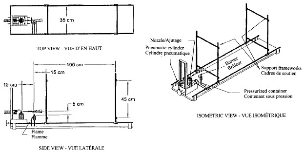
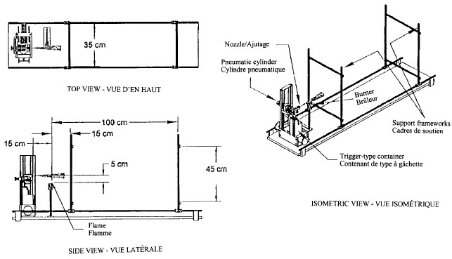
(a) a flammability tester, as illustrated in Figures 1 and 2 to the Schedule, that
(i) is constructed so that the spray container can be secured in place by means of a holding device, such as a three-pronged clamp affixed to a ring stand, in such a manner that the discharge from the spray container is in the horizontal plane,
(ii) may include a remote control device by which
(A) the valve of a pressurized container can be activated, such as a side-pull, caliper-type bicycle hand brake, or
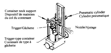
(B) the trigger or plunger of a pump-spray container can be pneumatically activated, as illustrated in Figures 3 and 4 to the Schedule,
(iii) has a vertically mounted burner that
(A) has an inside diameter of 1.2 mm,
(B) has a Luer-Lock 16-gauge needle affixed to a metal tube or another suitable device, and
(C) is placed at a distance of 15 cm from the discharge orifice of the spray container, which distance is to be measured horizontally between the vertical planes of the discharge orifice and the burner orifice, and
(iv) has two support frameworks, placed on the opposite side of the burner from the spray container, one at a distance of 15 cm from the burner and the other at a distance of 100 cm from the burner, each of which
(A) has an internal open space of 35 cm wide by 45 cm high,
(B) is constructed from metal or other non-flammable material,
(C) is mounted in a vertical plane perpendicular to the direction of discharge from the spray container, and
(D) is adjustable in the vertical plane;
(b) a cylinder of chemically pure grade propane fitted with a regulator capable of delivering pressure to the burner appropriate to maintaining a flame height of 5 cm; and
(c) loosely woven cotton fabric commonly referred to as cheesecloth that has, in the bleached state, a mass per unit area of not less than 35 g/m2 and not more than 65 g/m2.
Test Specimen
3 (1) When there are instructions by the manufacturer respecting the shaking of the spray container, a test must be conducted as follows, using each of three spray containers of the same product and of the same size:
(a) if shaking is applicable, shake and discharge the container three times in the manner described in paragraph 4(9)(a); or
(b) if shaking is not applicable, discharge the container three times in the manner described in paragraph 4(9)(b).
(2) When there are no instructions by the manufacturer respecting the shaking of the spray container, a test must be conducted as follows, using each of three spray containers of the same product and of the same size:
(a) without shaking the container, discharge it three times in the manner described in paragraph 4(9)(b); and
(b) shake and discharge the container a further three times in the manner described in paragraph 4(9)(a).
Procedure
4 (1) A test
(a) must be conducted at a room temperature of 22 ± 2°C in the absence of air currents, with an allowance made for a clearance of 50 cm beyond the support framework that is set at a distance of 100 cm from the burner; and
(b) may be conducted in a fume hood with the exhaust fan turned off and the protecting door lowered.
(2) Any fume must be removed from the test area and any residue cleaned up after each discharge.
(3) Before testing, each spray container must be
(a) maintained at a temperature of 22 ± 2°C for at least four hours; and
(b) primed by
(i) in the case of a pressurized container, discharging the container for five seconds, and
(ii) in the case of a pump-spray container, activating the trigger or pump using each of 18 N, 36 N and 54 N of force for each possible nozzle position until
(A) in the case of the “stream” position, a continuous stream is produced, and
(B) in the case of the “spray” position, a mist is produced.
(4) Install the first spray container in the holding device and ensure that the burner orifice is 15 cm from the discharge orifice of the spray container in the horizontal plane and 5 cm below it in the vertical plane and that the discharge orifice points in the direction of the burner.
(5) Adjust the burner to give a flame height of 5 cm and release a single trial discharge from the spray container.
(6) If the operation set out in subsection (5) does not produce a flame projection, lower the burner orifice by 5 cm and adjust the burner to give a flame height of 12 cm.
(7) Attach the cheesecloth to the flammability tester with bulldog clips or in any other manner so as to cover the entire internal space of the support framework set at a distance of 15 cm from the burner and verify that the cheesecloth is at a proper horizontal distance from the vertical plane of the burner orifice on the opposite side of the burner from the spray container.
(8) Adjust the height of the support framework so that the cheesecloth will intercept the line of flame projection.
(9) Prepare the spray container in accordance with the manufacturer’s instructions and
(a) if shaking is applicable,
(i) shake vigorously for five seconds, or for the period specified in the manufacturer’s instructions,
(ii) install the spray container in the holding device, and
(iii) 15 seconds after the cessation of shaking, release the discharge in accordance with subsection (10); or
(iv) [Repealed, SOR/2009-165, s. 20]
(b) if shaking is not applicable, install the spray container in the holding device and release the discharge in accordance with subsection (10), allowing the spray container to stand for at least 60 seconds between discharges.
(10) Discharge the spray container
(a) in the case of a pressurized container, for five seconds or until the cheesecloth ignites; or
(b) in the case of a pump-spray container, for three sprays or until the cheesecloth ignites.
(11) In the case of a pump-spray container, repeat the procedure set out in paragraph (10)(b) for each of 18 N, 36 N and 54 N of force for each possible nozzle position.
(12) If the cheesecloth attached to the support framework that is set at a distance of 15 cm from the burner ignites, the remaining discharges referred to in section 3 must be carried out in accordance with subsections (1) to (11) using a new piece of cheesecloth attached to the support framework that is set at a distance of 100 cm from the burner.
Determination and Reporting of Flame Projection and Flashback
5 (1) If at any time during the test the cheesecloth that is mounted at a distance of 100 cm from the burner is ignited, the length of the flame projection is 100 cm or more.
(2) If at any time during the test the cheesecloth that is mounted at a distance of 15 cm from the burner is ignited and, at all times during the test, the cheesecloth that is mounted at a distance of 100 cm from the burner remains unignited, the length of the flame projection is 15 cm or more but less than 100 cm.
(3) If at any time during the test the cheesecloth mounted at a distance of 15 cm from the burner is not ignited but there is a flame projection, the length of the flame projection is less than 15 cm.
6 The following test results must be recorded and kept for a period of at least three years after the testing is carried out:
(a) the length of the flame projection
(i) in the case of a pressurized container, for each discharge, and
(ii) in the case of a pump-spray container, for each discharge at each nozzle position and each force applied;
(b) a lack of flame projection resulting from any of the test discharges; and
(c) any flashback.
FIGURE 1Flammability TesterPressurized Container

FIGURE 2Flammability TesterPump-Spray Container

FIGURE 3Holding Apparatus for a Trigger-Type ContainerIsometric View

FIGURE 4Holding Apparatus for a Plunger Type or Pressurized ContainerIsometric View

- SOR/2009-165, ss. 18 to 21
- Date modified: