Government of Canada / Gouvernement du Canada
Symbol of the Government of Canada

Search

Motor Vehicle Restraint Systems and Booster Seats Safety Regulations (SOR/2010-90)

Regulations are current to 2024-03-06 and last amended on 2020-02-04. Previous Versions

SCHEDULE 7(Subsection 100(1), paragraphs 216(1)(a) and (b), 217(a), 315(1)(e), 407(e) and (f), 519(a) and (b), 520(a) and 615(1)(c))

Diagram of Interface Profile of Tether Strap Hook with measurements and specifications.

Figure 1 — Interface Profile of Tether Strap Hook

Notes:
  • 1 Dimensions in mm, except where otherwise indicated

  • 2 Drawing not to scale

Diagram of Interface Profile of Tether Strap Hook with Integrated Adjustment Hardware with measurements and specifications.

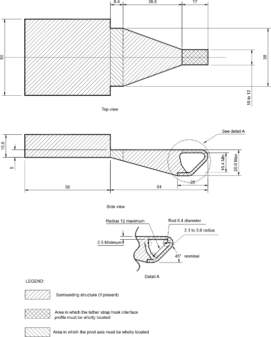
Figure 2 — Interface Profile of Tether Strap Hook with Integrated Adjustment Hardware

Notes:
  • 1 Dimensions in mm, except where otherwise indicated

  • 2 Drawing not to scale

Diagram of Three-dimensional Schematic View of Standard Seat Assembly Indicating Location of Seat Belt Anchorage Points with measurements and specifications.

Figure 3 — Three-dimensional Schematic View of Standard Seat Assembly Indicating Location of Seat Belt Anchorage Points

Notes:
  • 1 Dimensions in mm, except where otherwise indicated

  • 2 Drawing not to scale

  • 3 Lap belt anchorage points and continuous-loop lap and shoulder belt lower anchorage points are symmetrically located with respect to the SORL

Diagram of Three-dimensional Schematic View of Standard Seat Assembly Indicating Location of Lower Universal Anchorage System with specifications.

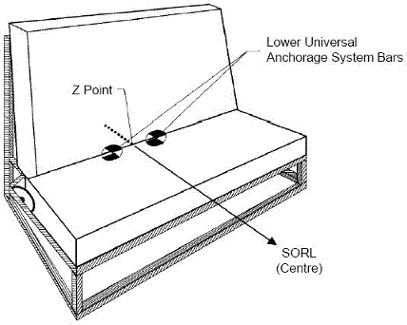
Figure 4 — Three-dimensional Schematic View of Standard Seat Assembly Indicating Location of Lower Universal Anchorage System

Notes:
  • 1 Drawing not to scale

  • 2 Transverse horizontal distance between the centre of the bars and the vertical plane containing the SORL is 140 mm

Diagram of Side View of Standard Seat Assembly Indicating Location of Seat Belt Anchorage Points with measurements and specifications.

Figure 5 — Side View of Standard Seat Assembly Indicating Location of Seat Belt Anchorage Points

Notes:
  • 1 Dimensions in mm, except where otherwise indicated

  • 2 Drawing not to scale

  • 3 User-ready tether anchorage point on rear package shelf located on the vertical longitudinal plane containing the SORL or located 544 mm right or left of the vertical longitudinal plane containing the SORL

Diagram of Side View of Standard Seat Assembly Indicating Location of Lower Universal Anchorage System with measurements and specifications.

Figure 6 — Side View of Standard Seat Assembly Indicating Location of Lower Universal Anchorage System

Notes:
  • 1 Dimensions in mm, except where otherwise indicated

  • 2 Drawing not to scale

  • 3 User-ready tether anchorage point on rear package shelf located on the vertical longitudinal plane containing the SORL or located 544 mm right or left of the vertical longitudinal plane containing the SORL

  • 4 Lower universal anchorage system bars located 102 mm forward of the Z point and 323 mm upward from floor

Diagram of Forward and Upper Excursion Limits for any Portion of Target Point on Either Side of Anthropomorphic Test Device Head with measurements and specifications.

Figure 7 — Forward and Upper Excursion Limits for any Portion of Target Point on Either Side of Anthropomorphic Test Device Head

Note: The illustrated limits move during dynamic testing

Diagram of Point X on Vertical Plane of Standard Seat Assembly with specifications.

Figure 8 — Point X on Vertical Plane of Standard Seat Assembly

Diagram of Rear and Side View of Checking Device for Lower Connector System - Envelope Dimensions with measurements and specifications.

Figure 9 — Rear and Side View of Checking Device for Lower Connector System - Envelope Dimensions

Notes:
  • 1 Dimensions in mm, except where otherwise indicated

  • 2 Drawing not to scale


Date modified: